
Abstract
In order to meet the requirements of output torque, efficiency and compact shape of micro-spindles for small parts machining, a two-stage axial micro air turbine spindle with an axial inlet and outlet is proposed. Based on the k-ω turbulence model of SST, the flow field and operation characteristics of the two-stage axial micro air turbine spindle were studied using computational fluid dynamics (CFD) combined with an experimental study. We obtained the air turbine spindle under different working conditions of the loss and torque characteristics. When the inlet pressure was 300 KPa, the output speed of the two-stage turbine was 100,000 rpm, 9% higher than that of a single-stage turbine output torque. The total torque reached 6.39 N·mm, and the maximum efficiency of the turbine and the spindle were 42.2% and 32.3%, respectively. Through the research on the innovative structure of the two-stage axial micro air turbine spindle, the overall performance of the principle prototype has been significantly improved and the problems of insufficient output torque and low working efficiency in high-speed micro-machining can be solved practically, which laid a solid foundation for improving the machining efficiency of small parts and reducing the size of micro machine tool.
Introduction
With the extensive demand for miniaturization and intelligentization of products in the fields of robotics, new power devices, modern medicine, and biological engineering, the processing of precision parts with characteristic sizes from microns to millimeters has attracted extensive attention.1–3 As a key component in micro-cutting technology, a micro-spindle should not only ensure a high rotation speed and high turning accuracy but also have a compact structure, compact size, and convenient installation.4–6 Because of their advantages such as easy to realize high speed, no heating during operation, compact structure, and high power density and durability, air turbines have been widely used in micro-spindles, and researchers have carried out a number of relevant studies.
Wang et al. 7 developed a new type of twin-blade TB-air turbine, which is composed of two parallel turbines with angular migration. It was verified by experiments that the vibration and flow noise of the TB-air turbine is 60% and 50% lower than that of traditional turbines, respectively. 6 In order to reduce the run-out of the turbine spindle in the axial and radial directions, Zhang et al. 8 developed an air dynamic pressure bearing capable of bearing both axial and radial forces, and carried out theoretical analysis and experiment on the bearing capacity and stiffness. The critical velocity, modal shape, and unbalanced response of the rotating subsystem were predicted and verified. Li et al.9,10 proposed a new type of micro air turbine spindle supported by a porous ceramic static bearing. The least squares method was used to establish the theoretical model of static error and dynamic response prediction. The size of the micro spindle was optimized. The radial run-out of the micro spindle was 6 μm, the outer diameter was 28 mm, and the length was 45 mm. The prototype of the air turbine spindle designed by Paul Harris et al. 11 used a radial-inflow/axial-outflow turbine, with an outer diameter of 25 mm and an axial length of 11.5 mm, and the maximum rotational speed of 100,000 rpm. The maximum energy efficiency of the turbine and spindle is 54% and 35% respectively, which is approximately 15% higher than that of the commercial micromachining spindle, but its larger external size makes it inconvenient to clamp. Müller et al.12,13 adopted the CFD simulation method to optimize the inlet nozzle diameter, air turbine diameter, and clearance size between the air turbine and the housing, and obtained the maximum power of 12 W when the nozzle diameter was 1.15 mm, the air turbine diameter was 7.3 mm, and the clearance between the turbine and the housing was 0.1 mm. Two types of micro air turbine spindles with a tangential inlet were experimentally studied. The maximum no-load speed of the first spindle was 466,000 rpm. When the speed was 300,000 rpm, the output power of titanium alloy and brass was 10 W. However, the efficiency of the spindle and the torque under variable working conditions were not studied in depth. To improve the torque of dental air turbine handpieces, a single nozzle of the tangential inlet was adopted by Makhsuda Juraeva et al.,14–16 and the outer diameter of the turbine was 5.65 mm. The turbine, shell, and air supply pipe were taken as a whole for the numerical analysis. The system was optimized by selecting the number of blades, blade angle, and the clearance between the turbine and the housing as the three main parameters. It was found that the improved performance of type 2 was better than that of type 1. Cho17,18 obtained two-stage motor schemes with different blade shapes by combining three nozzles, eight stators, and three stators with an average radius of 9.2 mm. The experimental study found that when the n-2 nozzle, R-2 rotor, and the S-3 stator were used, the rotor speed could reach 40,000–48,000 rpm, and the net output power could be increased to 38%. However, when used in micromachining, the spindle speed is low, which does not meet the requirements. Jahanmir et al. 19 developed an ultra-high speed spindle supported by a combined air dynamic pressure bearing, with a turbine diameter of 6 mm and double axial air inlet nozzle; the highest machining speed of aluminium alloy was up to 450,000 rpm. Anandan et al. 20 used two laser Doppler vibrator (LDV) systems to measure the run-out of the air turbine spindles in the direction of rotation sensitivity, and achieved good results. Commercially available spindles are offered STH from NSK America Corporation, ABL, Westwind, and Aerolas. The HTS1501S microspindle developed by NSK USA has a maximum speed of 150,000 rpm, an outside diameter of 55 mm, and a length of 129.7 mm. The highest rotational speed of the D1733 miniature spindle developed by Westwind Air Bearing can reach 250,000 rpm, but it has a diameter of 61.9 mm and a length of 182.8 mm. These two types of turbine spindle have a larger shape and are not suitable for miniature machine tool mounting, and their working efficiency is only 10%–25%.10,11
The focus of the above studies was to improve the spindle speed, run-out, stiffness, etc. Most air turbine spindles adopt a tangential inlet. Although it is easier to obtain a higher speed, it will make the turbine spindles larger in size and more complex in structure, making them unsuitable for clamping. The experiments were mainly aimed at a single stage condition, without an in-depth study on the turbine torque characteristics, losses, and efficiency under variable working conditions. In this paper, a kind of two-stage axial flow turbine pneumatic spindle with axial inlet and outlet is proposed to achieve better dynamic performance and reliable clamping property of the turbine spindle under a smaller size.
Implementation method and spindle structure
Blade profile parameters
A velocity triangle can be used to analyze the flows in turbines, energy transfer processes, and changes in the size and direction of the working medium flows, as well as to describe the blade types. Figure 1 shows the velocity triangle of a two-stage axial air turbine spindle, which is superposed by the velocity triangle of rotor I and rotor II. The front and rear characteristic sections of rotor I are represented by 1 and 2, and the front and rear characteristic sections of rotor II are represented by

Speed triangle of novel prototype.
In the adiabatic case, the specific power obtained by air per unit mass on rotor I and rotor II is expressed as follows:

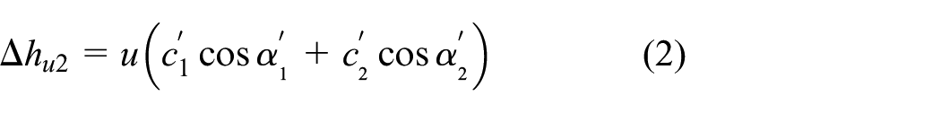
From formula (1) and formula (2), we can infer that the specific power of the two-stage turbine is equal to the sum of the specific powers of the first-stage turbine and the second-stage turbine. From this, it can be seen that the output specific power will be significantly improved by the additional stage turbine. The outer diameter of the nozzle, rotor I, guide turbine, and rotor II is 20 mm, and the number of blades is 12, 11, 12, and 13, respectively. The number of blades between adjacent turbines is prime to each other so that the output torque of air turbine spindle was not affected by the mounting Angle of rotor I and rotor II. The clearance between the rotor and the shell is 50 μm, and the clearance between the guide turbine and the shaft is 40 μm. The turbine blade profile parameters are presented in Table 1.
Blade profile parameters of the turbine.

Pneumatic spindle structure of double-stage axial flow micro turbine
The two-stage axial micro air turbine spindle consists of a shell, plug, distribution disc, nozzle, rotor I, guide turbine, rotor II, rotating shaft, bearing, and a retainer ring. The overall size is Ø 28 × 58. The rotor system composed of the nozzle, rotor I, guide turbine, rotor II, and the rotating shaft is shown in Figure 2. In order to ensure that the nozzle, rotor, and shell have the same thermal expansion rate and avoid jamming or wear, the shell, turbine, and nozzle are made of 7075 aluminium alloy and the shaft material is made of SUS304 stainless steel. The turbine spindle can simultaneously bear axial and radial forces. Therefore, the front and rear bearings are silicon oxide ceramic spindle bearings produced by GRW Company in Germany. The models are SV786 CTA and HYSV789 CTA, respectively.

Structure scheme and rotor system of proposed air spindle.
Flow field analysis
Selection of turbulence model
The flow field distribution of the two-stage axial micro air turbine spindle is extremely complex because of the influence of the high speed and the rotor/stator turbine interference. Therefore, the selection of the turbulence model is of vital importance. Through a comparison of the simulation and experimental results, the k-


Construction of simulation model and the grid validations for the computational domain
The overall calculation domain grid of the air turbine spindle is shown in Figure 3(a). The pink region is the rotation region, and the green region is the static region. Two nozzle inlet faces are set as the pressure inlet boundary, and six outlet faces are set as the pressure outlet boundary. The validity of the simulation model was verified when the inlet pressure was 300kPa and the rotation speed was 100,000, as shown in Figure 4(b). 3 When the number of grids is more than 4 million, the total output torque is within the allowable error range. Considering the efficiency and economy of simulation, the total number of grids is 3,997,545 and the total number of nodes is 709,923.

Construction of simulation model: (a) boundary condition setting and (b) the grid validation results.
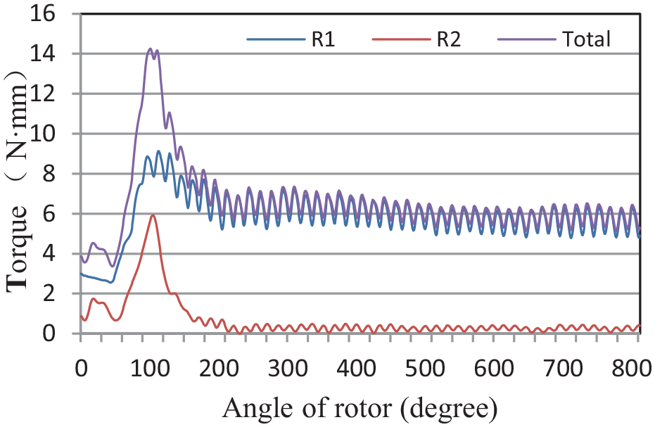
Torque according to rotation angle of the rotor.
In the design condition, the inlet pressure is 300 kPa, the outlet pressure is 115 kPa, and the design speed is 100,000 rpm. The main parameters of the solver are set as shown in Table 2.15,22
Solver conditions of the domain.

Flow field analysis
The torque variation rule of rotor I and rotor II with the rotation angle is obtained by using Fluent2020r1 monitoring, as shown in Figure 4. At the beginning of the rotation, the torque fluctuation of rotor I and rotor II is large. When the rotor shaft turns 500°, the torque of rotor I and rotor II presents periodic changes, and the fluctuation gradually decreases. Because of the double nozzle mode, the torque of rotor I changes one cycle at every 16.5° rotation, and the average torque is 5.88 N·mm. Compared with rotor I, the average torque of rotor II is 0.51 N·mm, which is 9% of the rotor, and the total torque of rotor 1 and rotor 2 is 6.12 N·mm.
Because of the double nozzle mode of operation, every rotation of the rotor is 16.5°, and the torque changes for one cycle. The average torque is 5.88 N.mm. Compared with that of rotor I, the average torque of rotor II is 0.51 N·mm, 9% that of rotor I, and the combined torque of rotor I and rotor II is 6.12 N·mm.
Figure 5 shows the velocity field of blades at different angles. Blade 2 and the nozzle at the position shown in Figure 5(a) is set to 0°. Because the nozzle is relative to the leading edge of blade 2, the air velocity from the nozzle is higher, reaching 334 m/s. When the airflow is split by blade 2, most of the high-speed airflow flows into the passage between blade 2 and blade 3 and a part of the airflow flows along the suction surface of blade 2. There is also a small part of airflow which flows along the gap between the nozzle and rotor I because of the blowing effect of rotor I, which will increase the loss. The airflow flowing out of rotor 1 impacts rotor II through the three adjacent passages of the guide turbine and then, flows out from the exit of the housing.

Velocity contour at different degrees: (a) position 1 (0°), (b) position 2 (10°), (c) position 3 (20°), and (d) position 4 (30°).
When the rotor shaft rotates to 10°, most of the high-speed airflow out of the nozzle flows into the passage between blade 2 and blade 3, impacting the pressure surface of blade 2. At this time, the maximum velocity of the airflow reaches 312 m/s and the output torque is 6.27 N·mm, reaching the maximum torque. The airflow changes direction through the two flow channels of the guide turbine and continues to impact rotor II. At this time, the torque of rotor 2 is only 0.15 N·mm, which indicates that the maximum torque of rotor II and rotor I do not occur at the same time.
When the rotor rotates to 20°, a part of the airflow impinges on the suction surface of blade 3, which will slow down the high-speed rotation of the shaft and reduce the output torque of the spindle. When the rotor shaft rotates to 30°, most of the airflow flows to the pressure surface of blade 3. Blade 3 works in the same manner as that of blade 2, and the output torque changes periodically.
The static pressure distribution on the pressure surface and the suction surface of the nozzle, rotor I, rotor II, and the guide turbine at the average blade height is shown in Figure 6 when the turbine torque is the maximum. Figure 6(a) shows that the maximum pressure difference between the two sides of the nozzle is at Z = 3 mm, which is the transition point of the nozzle from a straight line to an arc, and the pressure difference is 20 KPa. After this, the pressure difference gradually decreases until the airflow flows out of the nozzle and the pressure difference becomes zero. In Figure 6(b), the airflow in the passage of rotor I is subject to the centrifugal force, and the static pressure on the pressure surface is greater than that on the suction surface. It can be seen from the figure that the maximum pressure difference is at z = 7.5 mm, which is the symmetric centre point of the pressure surface or the suction surface, and the maximum pressure difference is 100 KPa. In Figure 6(c), the pressure surface and the suction surface of the guide turbine have small pressure differences at the inlet and at the pressure difference of 10 KPa, and the maximum pressure difference is at the symmetric centre point between the pressure surface and the suction surface. In Figure 6(d), the pressure fluctuation on the suction surface of rotor II is larger, and there is a negative pressure zone at the outlet and the entrance, indicating that there is an eddy current at the entrance.

Static pressure values of pressure surface and suction surface at average height: (a) nozzle, (b) rotor I, (c) guide turbine, and (d) rotor II.
Experiment of the two-stage axial micro air turbine spindle
Processing and assembly
In order to ensure the machining accuracy, the blank of the turbine was an aluminium alloy bar measuring Ф 25 × 50. The five-axis CNC milling centre (DMU monoblock 100) produced by German DMG was selected for machining. All of the surfaces were processed by using the same clamping method. The inner hole of the nozzle and the bearing outer ring, rotor, and shaft, and the shaft and the bearing were fitted with interference. During assembly, rotor II was first fitted to the shaft steps of the rotor position, and then, the guide turbine, rotor I, and nozzles were assembled in turn. During assembly, rotor II was first fitted to the step of the rotating shaft, and then, the guide turbine, rotor I, and nozzles were assembled in turn. A feeler gauge was used to ensure that the interval of each turbine was 1 mm. The assembled air turbine spindle is shown in Figure 7.

Prototype of air turbine spindle: (a) shape structure and (b) rotor system.
Construction of test platform
The testing principle is shown in Figure 8. This test platform could test the inlet and outlet pressure, inlet and outlet temperature, inlet flow rate and rotational speed, etc., and transmit the signal to the computer for data analysis through the data acquisition card. The test platform was equipped with three Pt100 platinum resistors, which were used to detect the temperature at the inlet and the outlet. The output signal was connected to the three-channel display instrument, which could display the airflow temperature in real time and transmit it to the data acquisition card. Two sets of pressure transmitters with a range of 0–1.6 MPa and an accuracy of 0.5% were equipped. The variable speed output was a 0–5 V voltage signal. The flow sensor (FSM2-NVF501-S081) of the CKD company was used for the flow measurement. The measurement resolution was 1 L/min, and the maximum measured flow rate was 500 L/min. The photoelectric sensor was used to detect the speed pulse signal and input it to the speed gauge. A photograph of the test platform is shown in Figure 9.

Schematic of test platform.
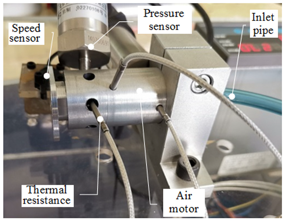
Photograph of test platform.
Experimental method
The rotor system of the air turbine spindle was composed of a bearing inner ring, rotating shaft, rotating impeller, and a speed measuring disk. When the spindle speed increased from 0 to n, it satisfied the following relation:

In order to test the torque of the motor during the process of starting and stopping, the following experimental scheme was adopted: During the test process, the sampling frequency was set by the test software to ensure that the sampling refresh time was greater than the acceleration time, and the torque change law of the spindle from the start to a stable rotation speed was obtained. The data were acquired in a continuous manner with a sampling frequency of 100 Hz and a total of eight channels. It took 81.92 s for one cycle of collection. First, we clicked on the test button, waited for 10 s, and turned on the air circuit switch; then, the spindle was accelerated to a start. When the spindle speed was stable, we waited for 10 s, turned off the air circuit switch to let the spindle slow down freely, and then waited 10 s to complete the data acquisition. The start–stop characteristic data within the range of 144–300 KPa was obtained by the pressure regulator; each start–stop curve included a start acceleration segment, a constant speed segment, and a stop deceleration segment. Figure 10 shows that during the start acceleration segment, with an increase in the inlet pressure, the higher the slope of the start acceleration segment was, the stronger was the acceleration capability. Under the design pressure, when the speed reached the constant speed segment, the fluctuation of the speed was very small and the output torque was equal to the sum of the friction torque and the load torque. With an increase in the pressure, the speed in the constant speed segment also increased. Under the action of the bearing friction force and the turbine resistance, the rotor shaft was decelerated to stop freely.

Speed as a function of time and supply pressure.
According to the variation law of the speed and time in the stop deceleration segment, the friction torque
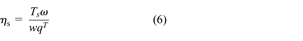
At the inlet pressures of 300 KPa, 224 KPa, and 180 KPa, the input and output characteristics of the air turbine spindle were tested. Using formulae (4), (5), and (6), we calculated the turbine efficiency and the spindle efficiency. The relationship between the turbine efficiency, velocity coefficient, and the inlet pressure is drawn, as shown in Figure 15. In formula (6), the spindle torque is

In order to analyze the cause of the loss of the air turbine spindle, the energy loss coefficient was used to measure the energy loss of each turbine. The ratio of the flow loss to the ideal energy in the static and dynamic cascades was called the energy loss coefficient, which is an index to measure the flow loss in cascades.22,23 It can be expressed as follows:


Result and discussion
Based on the simulation and experimental results, the operation characteristics and the efficiency of the air turbine spindle were analyzed along with the factors affecting the efficiency.
Analysis of rotor I and rotor II characteristics
Under different speeds and inlet pressures, the output torque of rotor I and rotor II was obtained by CFD analysis, as shown in Figure 11. As can be seen from the figure, with an increase in the inlet pressure, the output torque of rotor I and rotor II also increased. However, compared with that of rotor I, the torque generated by rotor II increased slightly. With an increase in the rotational speed, the output torque of both rotor I and rotor II decreased, while that of rotor I decreased faster and the output torque of rotor II changed gradually. At the design point, the rotational speed was 100,000 rpm, the inlet pressure was 300 KPa, the output torque of the first stage turbine was 5.88 N·mm, and the torque value of rotor II was 0.51 N·mm, which was 9% that of the first-stage turbine. This showed that although the two-stage axial air turbine spindle was more complex in structure than the single-stage air turbine spindle, it could increase the turbine torque significantly.

Torque curve as a function of solution and supply pressure.
Figure 12 shows the variation of torque with speed during the CFD analysis and the experimental test. When the inlet pressure was 300 KPa, 224 KPa, and 180 KPa, the CFD analysis and the experimental torque gradually decreased with an increase in the rotational speed. When the inlet pressure was 300 KPa, 224 KPa, and 180 KPa, the torque results of the CFD analysis and the experiment gradually decreased with an increase in the rotational speed, and the change trend of both was the same. Furthermore, with an increase in the rotation speed, the torque difference between them gradually decreased, which implied that the CFD analysis could objectively reveal the torque characteristics of the spindle. When the inlet pressure was 300 KPa, it reached the maximum rotation speed of 100,000 rpm, but it did not reach 120,000 rpm in the simulation analysis, indicating that the loss of the spindle profile and the end increased to some extent, which could not overcome the friction torque and continued to accelerate, but only fluctuated around 100,000 rpm. At the design point, the experimental torque was 5.72 N·mm, and at the inlet pressure of 224 KPa, the experimental rotational speed reached 96,000 rpm, but the output torque was only 2.5 N·mm, which was 43.4% of the torque at the design point. Note that the inlet pressure had a significant influence on the output torque; therefore, the spindle had to be allowed to work under the design conditions to ensure that the spindle had good torque characteristics.

Turbine torque curve for prototype turbine (experiment and CFD).
Figure 13 shows the influence of the inlet pressure and the rotational speed on the output power. The simulated power was calculated by multiplying the output torque and rotational speed of rotor I and rotor II. The simulation and experimental results revealed that the spindle power changed in a parabolic pattern and optimal speed was achieved under a certain inlet pressure to maximize the turbine output power. At the inlet pressure of 224 KPa, the maximum power was observed at the rotation speed of 70,000 rpm, and the maximum power was 32.2 W. When the inlet pressure was 300 KPa and the rotating speed was 95,000 rpm, the maximum power reached 69.1 W; while at the design point, the output power was 66.9 W. The design point was not selected at the maximum power point, which was intended to reduce the output power fluctuation when the load increased or the rotation speed decreased.

Effect of rotation speed on efficiency (measured and simulated).
Analysis of efficiency and loss
The velocity coefficient was defined as the ratio between the nozzle outlet velocity c and the turbine linear velocity u in the figure 14. When the air turbine spindle was working, the velocity coefficient had to be close to its optimal value. 24 Figure 15 shows that with an increase in the velocity coefficient, the distribution of the turbine efficiency and the spindle efficiency was parabolic. When the inlet pressure was 224 KPa and the velocity coefficient was 0.25, the maximum turbine efficiency reached 33.2%. When the inlet pressure was 300 KPa and the velocity coefficient was 0.28, the turbine efficiency was 42.4% and the spindle efficiency was 32.3%. Thus, we concluded that the turbine spindle could achieve higher efficiency when the spindle was operated at 70,000–110,000 rpm.
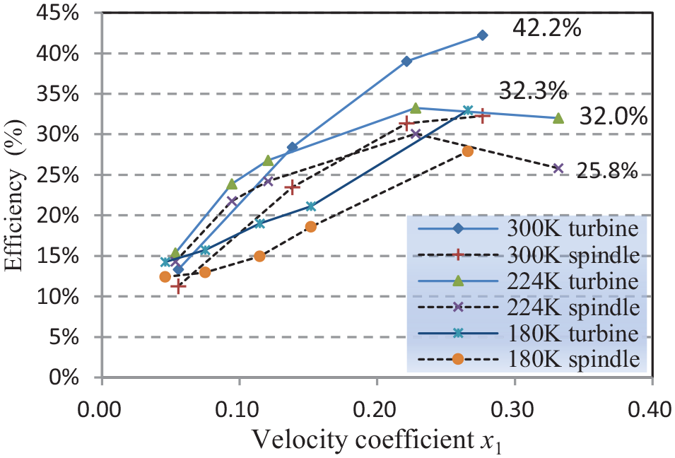
Efficiency as a function of velocity coefficient and supply pressure.
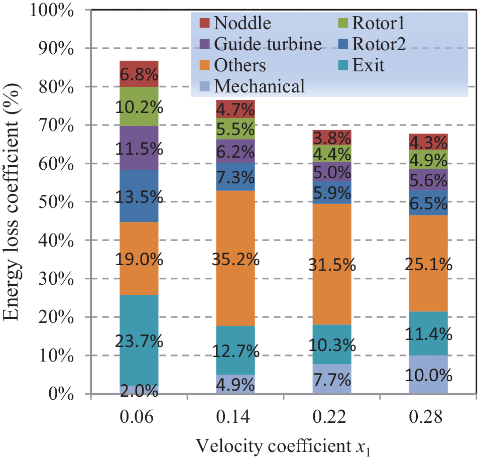
Energy loss coefficient at a supply pressure of 300 KPa.
Formulae (7) and (8) were programmed into the domain function to calculate the energy loss of the nozzle, rotor I, guide turbine, rotor II, and the exit. The mechanical loss was calculated on the basis of the experimental results. Other losses, such as partial air intake repulsion loss and leakage loss, were calculated indirectly by using the total experimental efficiency. Figure 15 revealed the energy loss coefficients of each part of the air turbine spindle at different rotational speeds when the inlet pressure was 300 KPa.
At the design working point, when the velocity coefficient was 0.28, the total loss coefficient was 67.7%, in which the loss of the nozzle, rotor I, guide turbine, and rotor II was 21.3%, which was the blade profile loss. Furthermore, the exit loss was 11.4%. As the velocity coefficient increased from 0.06 to 0.28, the bearing friction and the turbine repulsion losses increased, leading to a gradual increase in the mechanical loss. When the velocity coefficient was 0.22, the total loss coefficient was 68.7%, which indicated that the velocity coefficient was between 0.22 and 0.28, and the energy loss was 1%. This implied that the rotational speed c was between 80,000 and 100,000 rpm, which was an ideal working range.
The overall performance of the principle prototype has been significantly improved (Table 3).The efficiency of the prototype is slightly lower than the radial-inflow/axial-outflow turbine designed by Paul Harris, 11 but higher than that of the single-stage axial turbine designed by Jan Peirs 25 and the commercial air motor Spindle. 26 The power-to-weight ratio is second only to the turbine motor designed by Jan Peirs, but higher than the other two turbine spindles. Increasing the stages of axial flow turbines will increase the efficiency of air turbine spindles. However, the efficiency improvement is also affected by turbine type, aerodynamic parameters, the clearance of turbine and shell, velocity coefficient, etc. Comprehensive consideration should be taken in the design to further improve the axial work efficiency of two-stage axial turbine spindle.
Comparison of prototype and other air turbine spindle efficiency.

Conclusion
In this study, the realization and performance testing methods of the two-stage axial micro-turbine air spindle were investigated in depth, and the following results were obtained:
A two-stage axial micro air turbine spindle was developed to work in the double nozzle mode, compared with the tangential intake single turbine spindle, the air turbine spindle adopted an axial inlet and outlet, and the overall dimension of the turbine was only Ø 28 × 58. Moreover, its structure was more compact, convenient for clamping and installation, and very suitable for micro-machining. The power density and output performance have been improved greatly.
When the inlet pressure was 300 KPa and the output speed was 100,000 rpm, the output torque of the rotor II was 9% of the rotor I and the turbine torque reached 6.39 N·mm. the turbine spindle torque was 5.72 N·mm, the output spindle power was 59.9 W, and the mechanical efficiency was 32.3%. Among them, the total blade profile loss of the nozzle, rotor I, guide turbine, and rotor II was 21.3%; the exit loss was 11.4%; and the other losses were 25.1%. When the velocity coefficient was 0.22–0.28, the energy loss changed by approximately 1%; that is, when the speed was 80,000–100,000 rpm, it could be regarded as constant power, which was an ideal working area. In the next step, the support of the rotor system and the aerodynamic characteristics of the turbine need to be optimized to lay the foundation for commercial applications.
Footnotes
Appendix
Handling Editor: James Baldwin
Author contributions
L.J., H.X., and M.S., a doctoral student of G.Z., are the main authors of this paper. G.Z. was responsible for the overall planning of this research program, and L.J. was responsible for the writing of this paper and the experiment. Y.Q. was responsible for the aerodynamic design of turbines, and H.X. was responsible for the experimental setup. Z.X. handled the data analysis, grid division, and data processing with ANSYS.
Declaration of conflicting interests
The author(s) declared no potential conflicts of interest with respect to the research, authorship, and/or publication of this article.
Funding
The author(s) disclosed receipt of the following financial support for the research, authorship, and/or publication of this article: the research was funded by key projects of Natural Science Foundation of Inner Mongolia Autonomous Region (2017ZD02) and Scientific Research Program for Universities and Colleges in Inner Mongolia Autonomous Region (NJZY16089).