
Abstract
In this paper, we present a real-time optimal controller, Predictive Steering Control (PSC), to perform high-speed runway exit manoeuvres. PSC is developed based on a time-varying LQR with look-ahead. The aircraft’s ground dynamics are described by a high-fidelity nonlinear model. The proposed controller is compared with an Expert Pilot Model (EPM), which represents a pilot, in several different speed runway exit manoeuvres. With an improved road preview mechanism and optimal feedback gain, the predictive steering controller outperforms the expert pilot’s manual operations by executing the runway exit manoeuvre with a lower track error. To investigate the optimality of PSC, its solution is further optimised using a numerical optimal controller Generalized Optimal Control (GOC). PSC is shown to be close to the final optimal solution. To study robustness, PSC is tested with various aircraft configurations, road conditions and disturbances. The simulation results show that PSC is robust to disturbances within a normal range of operational parameters.
Introduction
In recent year, the aviation industry has seen large growth to meet rising demand of air passengers. The International Air Transport Association (IATA) expects the number of passengers to double to 7.8 billion in 2036. 1 It is an enormous test for air terminals and carriers to improve existing operating frameworks and satisfy this fundamental need throughout the following two decades. While great effort has been put on route and computerisation in flight, aircraft ground manoeuvres are as yet made exclusively based on pilots’ visual recognition and manual controls on engine thrust, control surfaces, steering and braking.
The airport operating efficiency and quality can be improved by automation of ground manoeuvres under various runway ambient conditions. For example, a stable and robust controller could potentially execute a faster runway turn-off than a pilot could achieve. Additionally, there are potential related economic advantages from reducing a given aircraft’s time spent on the runway, possibly allowing more aircraft to use existing infrastructure.
Part of the challenge faced while developing a control law for aircraft ground manoeuvres is the lack of aircraft mathematical models with suitable accuracy and complexity. In the literature, the bicycle model is typically used by control engineers to design a path-following controller for aircraft on the ground. However such models have been shown not able to capture the dynamics of certain manoeuvres especially when the aircraft’s rear track width and lateral load transfer play an important role in governing the observed dynamics, such as manoeuvres undertaken at high speed. 2 To overcome these shortcomings of typical aircraft ground models, Rankin et al. 3 proposed a six-degrees-of-freedom (DOF) nonlinear aircraft model. Nonlinear effects mainly come from the aerodynamics, tyre ground interactions and shock absorber response. Rankin’s model is developed based on the GARTEUR Simulink model, 4 which is an industrially validated model of an aircraft’s ground dynamics. The model used in this research is based in Rankin’s model.
Several previous works have considered the dynamics associated with aircraft manoeuvring on the ground. Rankin et al. 5 performed investigation of the aircraft’s lateral dynamics by bifurcation analysis, which revealed how the operational parameters such as thrust level and CG position affect the stability of steady-state turning solutions. While the bifurcation results give a global picture of the steady-state stability, they do not provide much information about what transient behaviours that the aircraft will experience in real operations, for example entering and exiting a corner. To improve on this limitation, Rankin et al. 6 proposed a general method to study transient loads during high and low speed runway exits, focusing on how the ground handling manoeuvre influenced each individual landing gear’s load (for two different aircraft weights). In this method, the runway exit manoruvre is parameterised via an approach velocity, while the steering input is predefined with the aid of a hyperbolic tangent function to mimick pilot steering. Under the assumption that braking only occurred for achieving the prescribed initial velocity before the manoeuvre was initiated, this research neglected longitudinal dynamics of the aircraft. Subsequent research by Huang et al. 7 applied optimal control to study the transient behaviours experienced by an aircraft when performing a ground manoeuvre, especially high-speed runway turnoff, where it was shown that the unusual layout of aircraft as ground vehicles means that braking and cornering does not need to be separated as it would in a car (because the brakes only act on the main gear, whilst the nose wheel steers the vehicle). The challenge of controlling an aircraft on the ground is therefore different, at high lateral accelerations, to other ground vehicles.
In order to automate aircraft ground manoeuvres, the aircraft needs to (a) identify a path and (b) follow that path with a sufficient safety margin. For high-speed runway exits, following the path centreline provides one means of operating with an appropirate safety margin (i.e. the aircraft is kept away from the edges of the runway). A number of control methods can potentially deal with this path following challenge. One possible solution is Model Predictive Control (MPC) which has been widely exploited in a variety of vehicle control tasks. Lenain et al. 8 presented an approach based on MPC which is able to execute a path following manoeuvre with small track error: the proposed controller corrects vehicle trajectories when sliding occurs, and is capable of compensating for delays caused by inertia and actuators. In Faulwasser and Findeisen, 9 the authors presented a controller developed based on Nonlinear Model Predictive Control (NMPC), which can deal with output path following tasks where states and inputs are constrained. They investigated the geometric solution of following a certain path by taking advantage of the transverse normal forms in order to stabilise the end penalty and terminal region. Considering the aircraft model used in our research is a highly nonlinear and complex dynamic system, an MPC framework would require significant computational power and time, hence difficult to be implemented for this specific application.
An alternative approach that is also broadly adopted in vehicle motion control is the linear quadratic (LQ) method. Unlike MPC, which is based on a closed loop optimisation, the LQ method can directly calculate the best control input with full state feedback. For a reference tracking motion control problem, Cole et al. proposed a controller based on LQ method and preview which could effectively balance tracking performance with limited capacity of actuators. 10 By computing a polynomial/spectral factorisation formulation, the optimal feed-forward solution can be obtained; it acts independently in combination with the feedback controller. Utilising the LQ method joined with a road-preview model, Sharp and Valtetsiotis 11 and Sharp 12 presented a solution to solve the optimal steering control problem based on a linear vehicle model. The road lookahead observed by the controller is shifted like a shift register every time-step with respect to the forward speed; by doing this the target path ahead is able to be updated and incorporated with the vehicle dynamics.
This research addresses how an aircraft can follow a predefined path with minimal deviation. It proposes a real-time controller for aircraft ground manoeuvres to achieve near-optimal path following performance. Computer simulations are used to evaluate the effectiveness of two real-time implementable controllers, in terms of their ability to maintain a specific ground path for an aircraft moving at high speed. The two controllers are compared to each other based on their ability to follow a pre-defined path, with lateral deviation from the path used as a measure of controller effectiveness. To demonstrate the optimality of the proposed controller, Generalised Optimal Control (GOC) is used to provide the best aircraft control performance possible. GOC can only be used as a benchmark, because it requires full knowledge of the future during a manoeuvre so is not possible to implement as a controller in reality.
The main contribution of this paper is the proposed Predictive Steering Control using linear quadratic regulator (LQR) method and trajectory preview. Specifically, it is a time-varying linear controller that is applicable to the control of nonlinear systems: at a range of equilibrium states (steady-state turning solutions), a linear discrete form of the system model is precomputed and stored. Subsequently, the optimal feedback gain at each of the equilibrium points can be determined by LQR. At any transient state, the specific feedback gain is obtained by interpolation using lateral acceleration as the measurement. Building on previous work, 13 the proposed controller is validated at various forward speeds in runway exit manoeuvres, in the presence of parameter and state disturbances.
The rest of this paper is organised as follows: Section II gives details of the fully parameterised aircraft model; Section III introduces the control methodologies; simulation results and a robustness study are shown in Section IV and V respectively; Section VI provides concluding remarks.
Mathematical model
In this research, we model the aircraft ground dynamics with a fully parameterised 6-DOF tricycle model with parameters chosen to represent a medium sized passenger aircraft, for example, A320. This model is based on Rankin’s model 3 which was initially derived from an industrially validated Simulink model. To capture the aircraft’s behavior accurately, especially when it is operating in the nonlinear region, additional parameters are introduced for the tyre model which can be adjusted for different tyre and road conditions.
Aircraft model
The overall frame of the aircraft is considered as a tricycle, to capture the influence of lateral load transfer between the main landing gears during cornering. The aircraft body coordinate system is defined as the origin at the centre of gravity(CG), the x-axis pointing forward, the y-axis pointing starboard and the z-axis pointing down. We determine the aircraft velocities in the body axis system, and positions and attitudes in the ground axis system. The derivation of the aircraft model is not within the scope of this paper. Details can be found in the previous work. 7 The aircraft model is described by a system of coupled ordinary differential equations (ODEs) which are derived from Newton’s Second Law by balancing forces and moments in each degree of freedom:

In equation (1), the system’s state space,

The aircraft CG position, dimensions with respect to CG, mass and moment of inertias are given in the appendix, Table 2.
At relatively low speeds experienced by an aircraft on the ground, the tyre/ground forces have dominant effects over the aerodynamic forces. Therefore, an accurate tyre model is needed to represent the real aircraft dynamics. The lateral forces generated by the tyres can be determined with a tyre model developed based on the GARTEUR Action Group. 4 A second subscript (N, R or L) denotes a model element referring to the nose, right or left landing gear respectively.
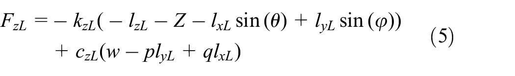
The vertical landing gear force is modelled by:


The stiffness coefficients
The longitudinal force is generated by rolling resistance, and is approximated for each wheel via the following equations:


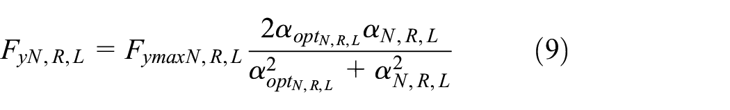
The lateral force on each gear is a nonlinear function with respect to the slip angle and vertical load:
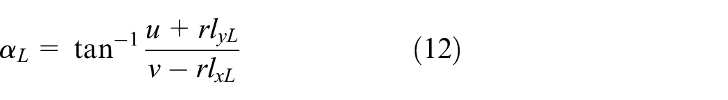
The slip angle is the vector sum of wheel forward velocity and lateral velocity, given by:


The maximum lateral force


where
Model linearisation and discretisation
For controller implementation, since the path preview model is defined in a discrete formulation, the aircraft dynamic model needs to be linearised and discretised before it can be incorporated with the path preview model. This linearisation is performed about an equilibrium point, obtained for a fixed forward speed. At an equilibrium point, the linearised model is formed:


where
For the PSC controller developed in this paper, the linearised models are precomputed at aircraft equilibria from 5 m/s to 20 m/s. The variation in lateral acceleration with steering angle and forward speed is shown in Figure 1. As speed-steering angle combinations lead to different maximum lateral acceleration achieved, lateral acceleration


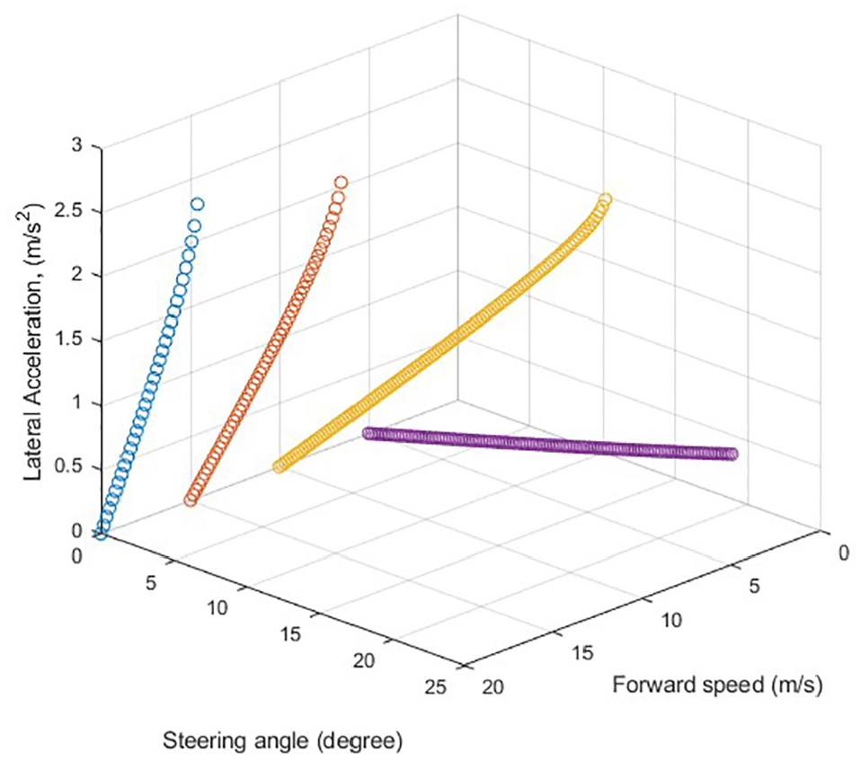
Equilibrium points at different speed and steering angle.
where subscript
Here, the acceleration experienced at the aircraft’s CG when in a steady state is:

For implementation, the obtained model is discretised (with a 10 ms time step):

with
Control methodology
In this research, we aim to design a real-time controller to automate aircraft ground manoeuvres. Previous work 7 has shown that optimal cornering with braking is achieved when the brakes are used at the start of the turn, with the majority of the turn conducted without braking. Hence, a constant speed runway exit manoeuvre with aircraft CG following the centreline is considered here. Three methods are employed to solve this problem. Firstly, an Expert Pilot Model is used to control the aircraft to follow a target path by correcting the predicted lateral deviation at a look-ahead point. This method is straight forward and computationally efficient, whilst providing a good representation of what a pilot would do when following a path. Secondly, a real-time optimal controller Predictive Steering Control (PSC) is proposed to achieve an optimal solution for path following manoeuvres. Lastly, a numerical optimal controller Generalized Optimal Control (GOC) is employed to investigate the optimal control for aircraft ground manoeuvres. Although not possible to use in real applications, where full state preview is not possible, the optimal solution from GOC is used here to judge the optimality of the real-time controllers.
Expert pilot model
The proposed Expert Pilot Model (EPM) is based on a simple driver model initially developed for ground vehicles.
14
By continuously adapting the steering, the aircraft is kept on a path towards a single reference point on the road ahead. The amount of look-ahead varies with speed, so a finite preview time


Calculation of preview point and lateral deviation from linear reference path.
where
To represent aircraft body axis system, unit vectors are defined by rotation of the global X facing vector through yaw angle

and the angle traversed along the arc is:

The preview point
The reference path is a linearly interpolated trace of (

The preview point

The signed deviation from the target path

Steering is then based on correction of this deviation from the target path and stabilization of yaw rate. The steering controller is effectively an integral controller with two gains with respect to lateral deviation

The proposed controller EPM relies on a 5s look-ahead and an integral gain
Predictive steering control (PSC)
Taking advantage of a similar preview mechanism as in the Expert Pilot Model method, PSC is developed based on an infinite discrete-time Linear Quadratic method. Rather than having only one preview point like EPM, PSC is on a basis of an estimated trajectory with equally spaced preview points over the preview horizon as shown in Figure 3. At any instant

Calculation of preview trajectory and lateral reference point.
In this method, the aircraft’s dynamics are interlinked with the previewed information of the road path via the path preview model, which is defined by a shift register 11


Combining the path preview and linearised aircraft models, the dynamic system to be controlled is represented as

The two models are linked via a quadratic cost function with respect to the lateral deviation of the aircraft CG from the target path

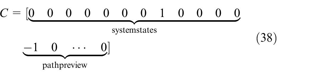
The R matrix is chosen to reflect the cost of using control, while the Q matrix is chosen to reflect the system objective. The optimal control sequence that minimises the cost function is obtained by:

with

The term P is the solution to the Discrete time Algebraic Riccati Equation (DARE), given by:

The original method by Sharp and Valtetsiotis
11
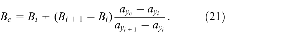
is improved by increasing the accuracy of look-ahead. Specifically, the whole sequence of y-reference

All control gains are precomputed at each equilibrium point in order to avoid recomputing the Riccati equation solution at every time-step: an example of the precomputed gains are shown in Figure 4. From this, a control gain vector can be obtained by interpolating (using lateral acceleration) between the stored control gains at any point along the trajectory. A preview time of 20 s is used throughout the paper: this long preview horizon is needed because the aircraft’s inertia means control actions take a long time to influence the output.
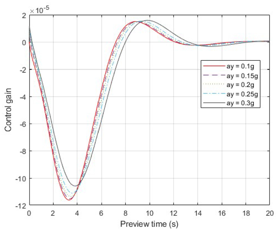
Control gains versus preview time.
Generalized optimal control
To find the theoretically-best solution for a ground manoeuvre, a numerical optimisation method of Generalized Optimal Control (GOC) is also considered here.16–18 The GOC algorithm is based on a gradient descent implementation of Pontryagin’s Maximum Principle for application in dynamical systems.19,20 It minimises a given cost function

A vector of co-states,

The co-states are given by:


The optimal control sequence is found at the minimum of the Hamiltonian function:
The optimal solution is identified via a discrete sequence of controls, with each control element held constant for an equal time interval

A gradient-based iterative optimisation can then be utilised to determine the optimal control sequence with the four steps outlined in Figure 5:
Step 1: For the current control sequence, the dynamic system is evaluated from the initial condition
Step 2: The residual cost
Step 3: The co-state system is used to simulate co-states in reverse-time from the final co-state
Step 4: The control sequence is updated by a line search optimisation along the steepest descent direction of the cost gradients, to minimise the cost function.
Steps 1–4 are repeatedly executed until suitable convergence is achieved.

Four steps of GoC algorithm.
Numerical simulations
In this section, the three control methods are evaluated using simulations. The effectiveness of the controllers is established by quantifying the difference between desired and actual paths followed. In the test case of a 45-degree runway exit, a typical landing weight of 54,500 kg and CG position at 30% of MAC are considered. The target path to follow is the centreline of the runway. The track cost is defined as a quadratic function of the lateral deviation from the centreline. Firstly, Predictive Steering Control (PSC) is compared with the Expert Pilot Model (EPM). Both controllers are tested at different speeds ranging from a low speed of 10m/s to a high speed of 25 m/s. Secondly, to evaluate the optimality of PSC, it is compared with the numerical optimal solution identified by GOC.
Expert pilot model versus predictive steering control
A

Aircraft trajectories of PSC and EPM at various speed.

Lateral deviation of PSC and EPM at various speed.
Control cost and track cost of PSC and EPM at various speed.

Figure 8 shows the steering input of both controllers, from which we can see the difference between their steering strategies. A positive steering angle indicates that the aircraft is steered to the right. In the pilot model, there is no steering input until the preview point reaches the first non-zero Y-reference. After the aircraft has passed the corner, it needs a long time and distance to settle down, which significantly increases the track cost. In comparison, PSC performs a preview-oscillation of steering which starts at a long distance before the corner. Since the road information propagates from the farthest preview point to the nearest preview point, the first non-zero reference point entering the preview system (which is positive in this right-hand exit manoeuvre) will be multiplied by the last element of the control gain sequence. As the previewed information is propagated within the path preview model, it will experience oscillatory control gains as depicted in Figure 4. Therefore, the aircraft is able to build up oscillatory yaw momentum as a result of the oscillations in the steering input. By doing this, the aircraft is able to follow the path more easily via a larger turning radius. Moreover, the aircraft settles down quickly and stays closer to the centreline without excessive corrections after the corner.

Steering angle of PSC and EPM at various speed.
The lateral accelerations are shown in Figure 9. Both controllers experience a similar level of maximum lateral acceleration around

Lateral acceleration of PSC and EPM at various speed.
As the forward speed rises to
In Figure 7, the track errors of both controllers are plotted against time. It can be seen that PSC is effective and efficient at tracking the target path at high speed. It takes the same control strategy of preview-oscillation of steering as in the lower speed case. This control strategy allows the aircraft to apply steering in advance to benefit from an enlarged turning radius, but without compromising the safety by operating too close to the apex. In this way, the maximum lateral deviation is largely reduced which leaves a wider safety margin for the runway exit manoeuvre. Unlike PSC, which uses a sequence of preview points, EPM is based on only one preview point. Therefore, EPM is not able to plan a manoeuvre ahead of time, because it does not have full knowledge of the road curvature. Steering angle and lateral acceleration are plotted in the bottom left panel of Figures 8 and 9 respectively. A massive steering input is built up over a short period between 15 s and 20 s. This rapid increase of steering angle would quickly correct the aircraft’s orientation and hence reduce the oscillatory correction after the corner. This sharp rise of steering angle, however, does not affect the aircraft lateral acceleration; PSC and EPM have a same level of maximum lateral acceleration around
To investigate extra high-speed runway turnoff, a forward speed of
Predictive steering control versus generalized optimal control
In this section, GOC is employed as a benchmark, based on which we can evaluate the optimality of PSC. PSC is compared with the optimal solution identified by GOC at 20 m/s. Here we use the same optimal solution as in Section 4.4. The aircraft trajectories of PSC and GOC are illustrated in Figure 10. It can be seen that PSC executes a runway exit manoeuvre which is very close to the optimal solution; the trajectory of PSC largely overlaps with the optimal trajectory. The difference between these two trajectories can hardly be seen despite the reduction of track cost achieved by GOC. The lateral deviations are plotted in the top panel of Figure 11, from which we can see that PSC and GOC have a similar track error history with the same peak value. However, two minor differences in the magnitude of lateral deviation can be observed; the aircraft controlled by PSC experiences slightly higher track error both before and after the corner. Additionally, the variation of sign illustrates how the aircraft negotiates this runway exit manoeuvre by oscillating around the centreline; PSC has a similar variation of sign compared to GOC, but with a small phase shift. The steering angles of both controllers are illustrated in the bottom panel. PSC takes advantage of the preview-oscillation steering strategy which is the same as the optimal solution. PSC applies an oscillatory steering input with lower magnitude compared to the optimal solution, which results in the increase of track cost. Since the implementation of PSC involves linearisation of the aircraft model and a rough estimation of the aircraft trajectory, its feedback control gain may not be the optimal one in terms of minimizing track error. But it still can be considered as a near-optimal controller, which is computationally efficient and suitable for real-time implementation.
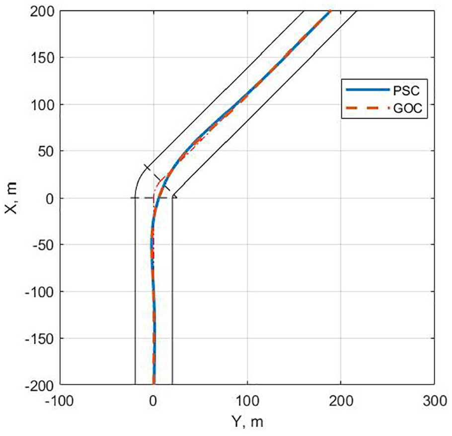
Aircraft trajectory of PSC and GOC at 20 m/s.

Comparison between PSC and GOC in a
Robustness analysis
The proposed PSC method and its compact version using constant control gain sequence will be examined in a 45-degree runway exit manoeuvre as the aircraft maintains a forward speed of 15 m/s. Throughout the robustness study in this section, the track cost and control cost are compared on a basis of the same set of control gain, which will be tested with various uncertainties and disturbances. The control gain to be tested is obtained at 15 m/s with the nominal configuration (a total weight of 54,500 Kg with a CG position of 30%MAC).
Firstly, a compact version of PSC is tested, using the same set of control gains obtained by taking an average of all the gains. Afterwards, it is tested with uncertainties including the aircraft’s total weight, CG position and coefficient of friction. These factors would largely change the dynamics of the aircraft and hence the stability of the controller. The baseline case is based on the nominal configuration on a dry road surface (friction coefficient of 1). Without re-tuning the controller, the compact version of PSC is employed to control the modified aircraft model on different runway conditions. The results are then compared with the baseline response.
Constant control gain
In the original method PSC, a transient control gain is identified via interpolation between the precomputed set of control gains. To make the control law more compact and computationally efficient, PSC with constant control gain (PSCC) is proposed here. The constant gain is obtained by taking the average of the whole set of control gains. The averaged control gains at different speeds are illustrated in Figure 12. PSCC is tested at various speeds from 10 m/s to 20 m/s. The track cost and control cost are illustrated in Figure 13. Using the averaged control gain, PSCC tends to apply less steering which results in a slightly higher track cost. Lateral deviation and lateral acceleration are plotted in Figure 14. It can be clearly seen that all the results by PSCC are very close to the baseline (PSC). Hence, this compact version of PSC offers comparable optimal performance to the full PSC controller. The following robustness analysis will be based on PSCC.

Averaged control gains at different speeds.

PSC versus PSCC at different speeds.

PSCC versus PSC at different speeds.
Weight and CG position
To investigate the proposed controller’s sensitivity to the two most basic parameters, weight and CG, the aircraft’s total mass will be varied between 49,500 kg and 64,500 kg, whilst the CG is varied between 26% and 32% of the mean aerodynamic chord. The controller has a fixed control gain which is based on the nominal configuration. The track cost and control cost are shown in Figure 15. It can be seen that within the range of standard operational mass and CG positions, the proposed control law is stable and valid in the presence of uncertainties. Particularly, with a more rearward CG position, the controller achieves a lower track cost with less actuation. Considering an aircraft’s CG usually moves backward due to the change of fuel load, uncertainties in total mass would be compensated for by this effect. Trajectories are plotted with the three typical configurations as shown in Figure 16. The variation of track cost doesn’t result in a big difference in trajectory, which implies that the controller is robust to varying mass and CG position.

Control cost and track cost for different mass and CG position.

Aircraft trajectories for different configurations.
Runway condition
In addition to the mass and CG, tyre/ground friction is another factor that would greatly change the aircraft’s behaviour on the ground. Tyre/ground forces are mainly affected by the runway condition. PSCC is then examined on different road conditions with coefficient of friction varying from the baseline of 1 to 0.6. The forward speed is set to 15 m/s which is a typical exit speed. The track cost and control cost are illustrated in Figure 17. With decreased coefficient of friction, both the track cost and control cost increase dramatically. Trajectories for COF of 0.8, 0.7 and 0.6 are depicted in Figure 18. The controller can safely cope with COF greater than 0.7 with maximum lateral deviation around 6 meters as shown in Figure 19. When COF goes down to 0.6, it becomes challenging to make a 45-degree runway exit manoeuvre at this speed. The aircraft overshoots the centreline for more than 10 meters before the track error can be corrected by significant steering actuation. Therefore,with COF lower than 0.7, the forward speed must be reduced and the control gain should be re-tuned accordingly.

Track cost and control cost on different runway conditions.

Trajectories on different runway conditions.

Lateral deviation and steering angle on different runway conditions.
Crosswind disturbance
In real operations, aircraft may experience crosswinds on landing. To demonstrate potential operational robustness, the EPM and PSCC controllers are evaluated in the presence of a crosswind. In this analysis, the crosswind acts left to right in the figures, generating a negative yaw moment on the aircraft. From the track cost and control cost as illustrated in Figure 20, it can be seen PSCC tends to use more steering to achieve the same level of total track error. Figure 21 shows the lateral deviation and steering input. An extra amount of steering is applied to compensate the negative yaw moment caused by the crosswind. The controller shows good robustness in the presence of gust wind.

Track cost and control cost with gust wind.

Lateral deviation and control input with gust wind.
Conclusion
The presented Predictive Steering Control method can be employed to drive the aircraft to follow a target path. This proposed control law is computationally efficient so that it can be implemented in real-time. A 45-degree runway exit manoeuvre at various speeds is considered to test the proposed controller. In comparison with a simple Expert Pilot Model controller which emulates a human pilot’s driving behaviours, PSC achieves better performance by using a linear quadratic method with look-ahead. Taking advantage of 20 s of road preview, the controller starts to steer in advance to the corner. Specifically, the aircraft takes a preview-oscillation of steering to achieve a larger turning radius. The solution by PSC is compared with a solution from GOC, which identifies the numerically-optimal solution. The result shows that PSC has been very close to the optimal solution. One of the strengths of PSC is that it requires very little computational power while delivering a near-optimal solution.
To make PSC more compact and efficient, the interpolation between control gains for different lateral acceleration levels is replaced by a constant control gain (PSCC). PSCC turns out to be as effective as PSC although it leads to a slightly increased track cost. A comprehensive robustness study has been carried out for PSCC with respect to uncertainties(mass, CG and road conditions) and disturbance (crosswind). PSCC shows good robustness to uncertainty and disturbance of the standard operational configurations and conditions.
The presented control law mainly concerns lateral control with a constant forward speed. In practice, however, brakes and thrust can also be used to help make a manoeuvre. Future work will focus on longitudinal control and optimisation.
Footnotes
Appendix
Tyre parameters and value.
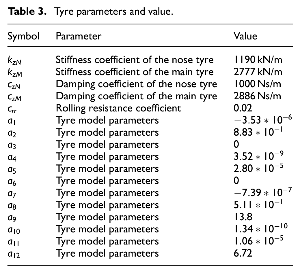
| Symbol | Parameter | Value |
|---|---|---|
| Stiffness coefficient of the nose tyre | 1190 kN/m | |
| Stiffness coefficient of the main tyre | 2777 kN/m | |
| Damping coefficient of the nose tyre | 1000 Ns/m | |
| Damping coefficient of the main tyre | 2886 Ns/m | |
| Rolling resistance coefficient | 0.02 | |
| Tyre model parameters | ||
| Tyre model parameters | ||
| Tyre model parameters | 0 | |
| Tyre model parameters | ||
| Tyre model parameters | ||
| Tyre model parameters | 0 | |
| Tyre model parameters | ||
| Tyre model parameters | ||
| Tyre model parameters | 13.8 | |
| Tyre model parameters | ||
| Tyre model parameters | ||
| Tyre model parameters | 6.72 |
Handling Editor: James Baldwin
Declaration of conflicting interests
The author(s) declared no potential conflicts of interest with respect to the research, authorship, and/or publication of this article.
Funding
The author(s) received no financial support for the research, authorship, and/or publication of this article.