
Abstract
This paper studies the force and deformation of the connecting channel in Ningbo rail transit construction, which firstly used the mechanical shield method. Steel-concrete composite structural segments are used in the T-joint of connecting channel. The cutting part of the segments are replaced by the concrete and fiberglass instead of reinforced concrete. Basing on a variety of three-dimensional design software and ABAQUS finite element analysis software, a refined finite element analysis model of the special segments is established. By considering the influence of curved joint bolts, the force analysis of the special segments under the structural state before and after construction is performed. According to the analysis and comparison of the deformation of the segments with and without the bolts, it is concluded that the steel-concrete segments can withstand the pressure of the soil before and after the construction. Suggestions for the safety of the design and construction of the segments are put forward.
Introduction
The use of underground space for developing public transportation has been continuously growing in recent years, particularly in medium and large cities of developing countries.1–3 To deploy underground space one has to construct large tunnels. Most of tunnels can be excavated by using drilling, blasting, or excavation by using tunneling boring machines (i.e. shield machines). 4 Excavation using shield machines has been considered as the safe, fast, and efficient method of tunneling, which could mitigate many risks related to ground conditions. When a shield machine is used for excavation the soil is excavated by the cutting wheel at the front end of the shield and being removed through the machinery as slurry or left as-is depending on the type of the machine. A set of hydraulic jacks are used to push the machine forward. Then, the erector is used to pick up precast concrete segments and locate them in the designed position to form a new tunnel ring. Modern shield machines typically consist of the rotating cutting wheel, called a cutter head, followed by a main bearing, a thrust system and trailing support mechanisms. 5 The design of shield machines to be used for a particular project is dependent on the geology of the site, the amount of ground water present there and the structural conditions surrounding the site. Shield excavation used in difficult conditions such as weaker rock and/or high depth may lead to shield jamming and shield entrapment because of insufficient thrust force that cannot overcome the shield skin friction between the machine and the ground. 6 For successful tunneling in such conditions, it is essential to study the pertinent ground and operational factors and their impact on ground behavior, to assess the possibility of shield entrapment and to develop possible safeguards to mitigate the related risks. 7
Many studies were carried out in last decade to understand the interaction mechanisms between the rock mass and shields, lining and backfilling. For example, Mo and Chen 8 conducted a finite element analysis on different segment rings of tunnels by considering the squeezing action of tail brush under attitude deflection, jacking force, grouting pressure and earth pressure. It was found that the squeezing action could lead excessive dislocation of segments. Hasanpour 9 developed a 3D simulation for mechanized tunneling to evaluate the potential of excessive ground convergence and to predict the loads on the shield during excavation for assessing the risks of machine entrapment. Zhang et al. 10 proposed an approximate method for calculating the loads acting on the cutterhead–ground interface of an earth pressure balance shield machine and developed the expressions of normal and tangential stresses acting on the tunneling interface between cutterhead and ground. Wang et al. 11 presented a probabilistic analysis model of shield-driven tunnels in multiple strata considering stratigraphic uncertainty. In their model, the underground soil stratigraphic profile was treated as a Markov random field with specific energy functions and able to describe the inherent anisotropic and nonstationary spatial correlation of lithological units in the subsurface stratigraphic structure. The model was used to evaluate the effects of stratigraphic uncertainty on the structural performance of shield-driven tunnels. Hasanpour et al. 6 performed a parametric study on the controlling parameters influencing the risks of shield tunneling in squeezing ground by using a full 3D numerical simulation to examine the influence of various factors on machine entrapment. Berthoz et al. 12 examined the stress-strain behavior of various different soils during tunnel excavation using earth pressure balance shields. Gong et al. 13 presented a combined experimental and numerical study on a recently built tunnel below the Yangtze River in China using shield machines to investigate the sealant and mechanical behavior of gasketed joints. More recently, several researchers have used 3D finite element analysis models to investigate the behavior of tunnel lining, 14 and the long-term soil deformation and settlement induced in shield tunneling.15,16
The segments are the main structural components in the shield tunneling. During the construction, the tunnel segments are subjected to various different types of loadings, such as that from surrounding soil, saturated water, self-weight, settlement of foundation, and recoil of shield machines. Liu et al. 17 carried out an on-site monitoring analysis and performed a 3D finite element analysis on the mechanical behavior of shield tunnel segments during construction, and examined the stress and displacement characteristics of the segments. However, the refined 3D model of segments is less researched. The biggest difficulty is to establish the reinforced concrete structures, especially to get the steel cage embedded in the concrete. Han et al. 18 modeled interface elements as the contact between concrete and steel tube. The interface elements are composed of the matching surfaces of steel and concrete, where hard contact is defined in the normal direction of surfaces and friction contact is defined in the tangent direction. Seok et al. 19 simulated bond-zone behavior in the pullout test of reinforced concrete and defined hard contact between the concrete and steel bars, which allow no penetration but separation. Yang et al. 20 presented a 3D element model to trace the behavior of corroded beam-column joints, where eight-node linear solid elements were used for concrete and truss elements were adopted and embedded in modeling the reinforcements.
Chen et al. 21 did a structural analysis on shield tunnel segments by using finite element method. It was found that different outside tunnel loads along the longitudinal direction during the construction phase made the displacement and stress change in the same direction of the tunnel, which lead to different deformation characteristics in individual segments. He et al. 22 used an electrical measurement method to analyze the stress variation of the shield tunnel segments at the T-joint between the main and connecting tunnels. They also compared the stresses between the steel segments and the adjacent concrete segments. Cavalaro et al. 23 presented a numerical simulation on the gaps between segments and the cracks in segments, and obtained the forces and possible structural cracks caused by the use of different segments. Molins et al. 24 conducted the test of vertical steel fiber reinforced concrete segment rings to examine the structural behavior of shield tunnel segments during the construction.
The literature survey described above shows that there have been extensive studies on the analysis and performance of structural systems related to shield tunneling using both experimental and numerical methods. However, there is lack of the study on the detailed mechanical behavior analysis of composite segments used in shield tunneling under different working conditions. These conditions include the design condition before excavating, the unloaded condition considering the influence of lateral soil excavation, the overloaded condition caused by piling and existing buildings above the tunnel, and the ultimate limited condition considering overload when the excavation is completed.
In this paper, a finite element analysis model is developed for analyzing the mechanical behaviors of composite segments used in the main tunnel of Ningbo Rail Transit under various different working conditions with considering different geological conditions, different embedded depths before and after the construction. From the obtained stresses and deformations of the composite segments the safety of the composite shield segments is also examined and discussed.
Description of tunnel structural systems
In tunnel systems, connecting channels are usually required when the length between the two consecutive sections of a main tunnel is longer than 600 m because of the safety issue. The principal function of the connecting channels is to serve as a security conduit, which acts as a disaster prevention and escape facility during the operation of tunnels. In general, the size of the connecting channels is smaller than that of the main tunnels and their construction is normally arranged after the main tunnels are constructed. In this sense, the connecting channel is also called “holes in the holes”. The interface between a connecting channel and a main tunnel is known as “T-joint”. Figure 1 graphically shows a typical tunnel system where two main tunnels are linked by a connecting channel.

Schematic of a tunnel system with a connecting channel: (a) 2D and (b) 3D views of the tunnel system.
Freezing and mining construction method is commonly used for the construction of connecting channels.25–28 The method utilizes a freezing equipment and liquid nitrogen to freeze the wet soil and gravel in the working site for temporary solidification before the excavation is executed. However, the method has the weaknesses such as time consuming and high costing. In addition, it could lead soil shrinkage and sinking, which may have a long-term structural effect on surrounding buildings. Shield construction is a good option for constructing connecting channels. The main difficulty is the construction surface of the connecting channels that is too small to use conventional large excavation shield machines. In addition, the construction of the T-joint at the two ends of the connecting channel could also affect the structural stability of the main tunnels. Therefore, there is a need to develop special shield machines for the construction of connecting channels and to examine the effect of the connecting channel construction on the structural stability of connected main tunnels.
A special shield machine has been designed for the construction of the connecting channels in the tunnel system at Ningbo Metro Line 3. The entire tunnel consists of two main tunnels and a connecting channel, similar to that shown in Figure 1. To strengthen the structural stability of the connected main tunnels, a special T-joint is used at each end of the connecting channel. Figure 2 shows the geometry of the T-joint used in the main tunnel, which is assembled by three ring-shells in parallel along the longitudinal direction of the main tunnel. Each ring-shell has outer diameter of 6.2 m, inner diameter of 5.5 m, and length of 1.5 m. The diameter of the hole on the surface is 3.3 m, which represents the pathway to the connecting channel. Each ring-shell has six blocks: including three standard blocks made using steel reinforced concrete, one crown sealing block also made using steel reinforced concrete, and two excavating blocks made by using thick steel mesh plate and fiberglass reinforced concrete (see Figure 3). The material used in the place of the hole linking to the connecting channel is also the fiberglass reinforced concrete. In order to strength the bond strength between the steel mesh plate and fiber reinforced concrete in the excavating blocks, shear studs are welded on the steel mesh plate. Connections between blocks are provided using straight bolts in longitudinal direction and curved bolts in circumferential direction, respectively.

Geometry of T-joint in Ningbo Metro Line 3: (a) side view and (b) front view.

Details of T-joint used in Ningbo Metro Line 3.
The six excavating blocks in the three ring-shells used in the T-joint are specially designed and manufactured based on various different loading conditions by considering the effect of construction of connecting channels, the geology of the site, the amount of ground water present there and the structural conditions surrounding the site. The structural analysis of the T-joint is carried out by using finite element methods. The details of the finite element analysis model are described in Section 3. The corresponding results and discussion of the results are shown in Section 4.
Finite element analysis model of T-joint
The geometric model of the T-joint to be analyzed is the same as that shown in Figure 3, which is drawn using AutoCAD and then input into ABAQUS for pre-process. Note that, in the standard blocks and crown sealing blocks three separate volumes are used for three different materials, namely the reinforcing steel bars, bolts, and concrete (C40), respectively. In the excavating blocks four separate volumes are used for four different materials, namely the steel mesh plate and studs, bolts, reinforcing fiberglass bars, and concrete (C50), respectively. In the hole two volumes are used; one is for reinforcing fiberglass bars and the other is for concrete (C40), respectively. Line elements are used for the reinforcing steel bars and reinforcing fiberglass bars, whereas solid elements are used for the steel mesh plate, studs, bolts, and concrete. Contact elements are built in the solid elements between the steel mesh plate and concrete, between the steel studs and concrete, and between the bolts and concrete. The line elements for the reinforcing bars are directly embedded in the solid elements for which no contact element is used. Figure 4 shows the arrangement of different materials used in the T-joint and the structural meshes of the T-joint before and after the excavation used in the analysis.
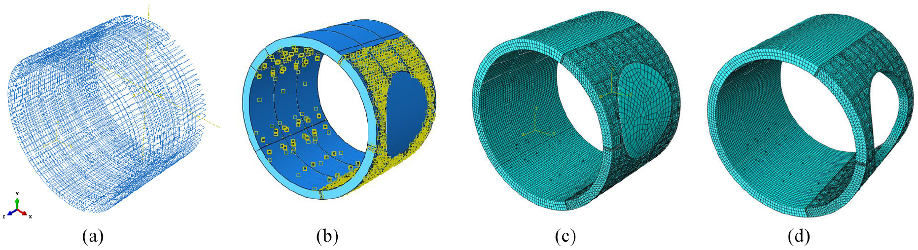
(a) Reinforcing steel bars in standard blocks and crown sealing blocks and reinforcing fiberglass bars in excavating blocks, (b) concrete (blue color) and contact surfaces (yellow color), (c) finite element meshes of T-joint beforeexcavation, and (d) finite element meshes of T-joint after excavation.
The mechanical properties for concrete (C40 and C50), reinforcing steel bars, reinforcing fiberglass bars, steel mesh plate, studs, and bolts used in the analysis are given in Table 1. It is assumed in the present analysis that, the reinforcing steel is the elastic-perfectly plastic material, the reinforcing fiberglass is the elastic material, the steel mesh plate is the elastic-perfectly plastic material, the steel studs and bolts are the elastoplastic material with a bilinear stress-strain curve with ultimate strength 600 MPa and tangent modulus 2.08 GPa. The model employed for concrete is the continuum, plasticity-based damage model built in ABAQUS software.29–30 The model assumes that the two failure mechanisms are tensile cracking and compressive crushing. The evolution of the yield or failure surface is controlled by the tensile and compressive hardening strains, which are linked to failure mechanisms under tension and compression loading, respectively.
Mechanical properties of materials used in analysis.

The contact between segments is assumed as surface-to-surface contact mode. The friction contact surface with a friction coefficient of 0.28 is used to model contact between blocks, in which the two contact surfaces are allowed to separate and slid but no penetration. The small sliding contact surface is used to model the contact between the bolts and concrete and between the studs and concrete. Small-sliding contact assumes there could be relatively little sliding of one surface along the other and is based on linearized approximations of the master surface per constraint. The constraint between steel cage and concrete is assumed as “Embedded” to simulate the reinforced concrete segments.
The loads on the T-joint involve the aboveground loading, soil and water pressures, self-weight of the materials (see Figure 5(a)), as well as the mechanical loads generated during the construction of connecting channels. Note that some of these loadings are different at different construction stages. For the convenience of analysis, herein we consider three different loading cases, namely the design-loading case; under-loading case; and over-loading case. In the design-loading case the loads applied to the T-joint include the soil and water pressures surrounding the T-joint and the self-weight of the materials. In the under-loading case the loads applied to the T-joint include the soil and water pressures surrounding part of the T-joint due to the excavation of connecting channel, plus the self-weight of the materials. In the over-loading case the loads applied to the T-joint include the soil and water pressures surrounding the T-joint, the self-weight of the materials, and the aboveground loads generated due to the storage of waste/construction materials on the ground. Taking into account the construction site conditions in Ningbo Metro Line 3, the total loading on the T-joint in each loading case is calculated and is shown in Figure 5(b) and 5(c).
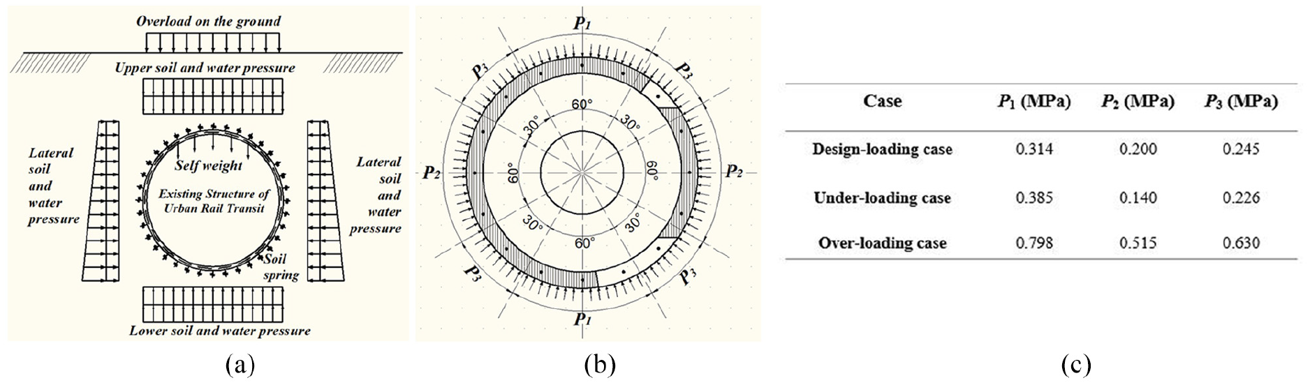
(a) Schematic of loadings on T-joint, (b) loading model used in analysis, and (c) loading values used in three different cases.
Since the connecting channel, that is, the special rings are set about every 600 m along the main tunnel, the longitudinal and circumferential displacements of their two sides are considered as fixed. In the present simulation, the longitudinal and circumferential displacements of the interface are set as zero, as shown in Figure 6.
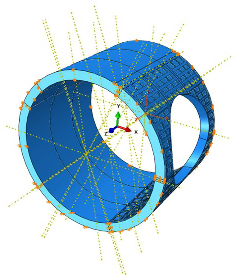
The boundary conditions set on the three-ring model.
Simulation results and analysis
Nephograms of stress, strain and displacement under three loading cases are extracted by using post-processor of ABAQUS. For investigating the effects of curved bolts and steel/fiberglass reinforced bars in the segments, the results of the models with and without curved bolts are compared. The position of maximum stress and displacement are found.
Stress and deformation analysis of special rings before excavation
The von-Mises stress, radial (R-direction in cylindrical coordinates) and circumferential displacements (T-direction in cylindrical coordinates) of special segments under three loading cases, are respectively shown in Figures 7–9. According to Figure 7, the maximum von-Mises stress appears in the longitudinal bolt between the crown sealing blocks in three loading cases. The shear caused by the dislocation of segments in the radial direction increases the von-Mises stress. In Figure 8, the maximum radial displacement in all three cases occurs in the seams between the special segments where the steel structure is weakest. The maximum circumferential displacement occurs in the interface between the excavated concrete part and steel structures, which is induced by the deformation incompatibility of two parts, shown in Figure 9. In contrast, the longitudinal deformation is found to be very small, and thus is not discussed further here.
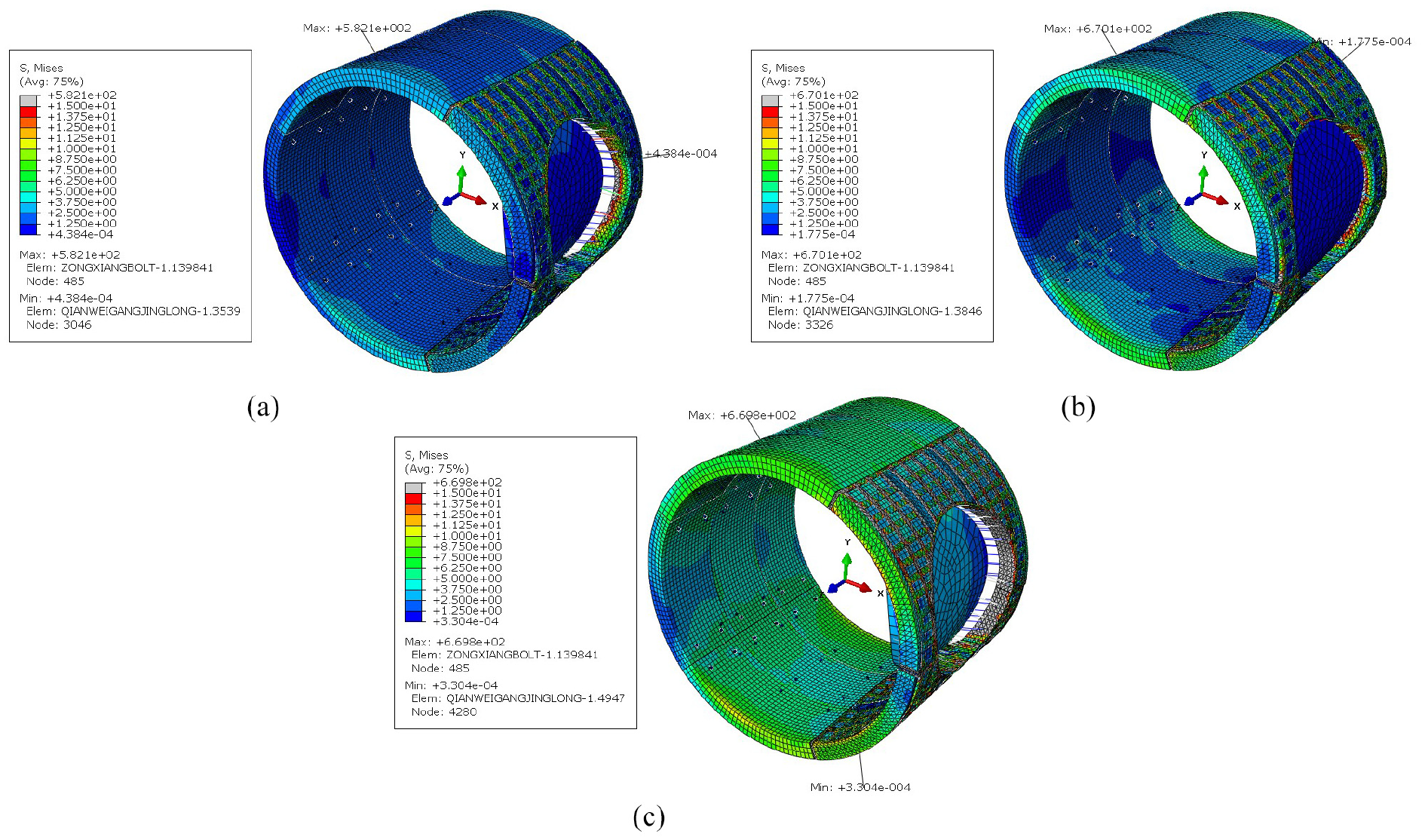
Stress nephograms of special rings before excavation in three loading cases: (a) design loading case, (b) unloaded case, and (c) overloaded case.

Radial displacement of cutting piece with cutting block under three loading cases: (a) design loading case, (b) unloaded case, and (c) Overloaded case.
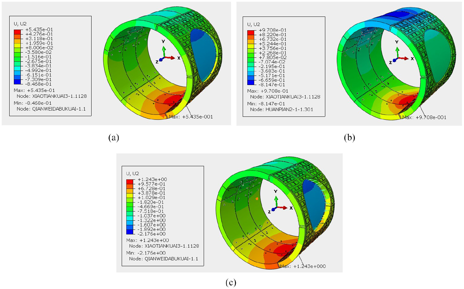
Circumferential displacement of rings before excavation under three loading cases: (a) design loading case, (b) unloaded case, and (c) Overloaded case.
Table 2 shows the maximum stresses and the maximum displacements in all directions under three loading cases. From Table 2, it could be noticed that the maximum stress in fiberglass had reached to the ultimate strength of 550 MPa in the overloaded case, which will lead to the fracture of fiberglass. The stress examination in fiberglass shows that 6–8 fiberglass bars on four corners of the concrete of the entire model will reach this limit situation. While since the fiberglass finally should be cut, the situation is neglected. It is also noticed from the table that the maximum von-Mises stress and shear stress have reached the ultimate strength and shear strength.
Corresponding calculation results before excavation under three loading cases.
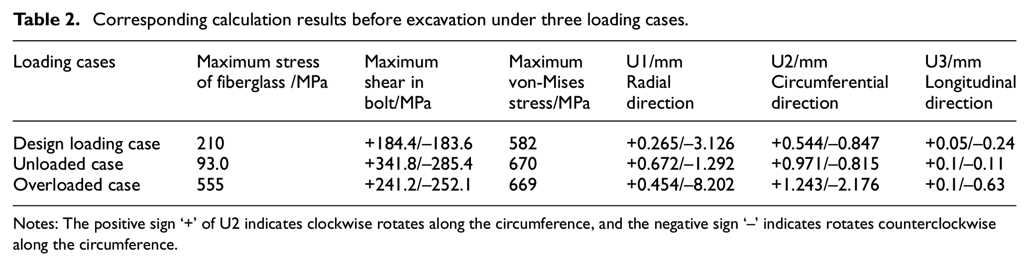
Notes: The positive sign ‘+’ of U2 indicates clockwise rotates along the circumference, and the negative sign ‘–’ indicates rotates counterclockwise along the circumference.
Further, it is found that the maximum strain of the concrete around the bolts is about 5*10−5, which is less than 10−4, and thus is considered as safe enough from the failure of the concrete.
Stress and deformation analysis of special rings after excavation
The simulation of excavated special rings is implemented to evaluate the structural strength and structural stability. From Figures 10–12, it can be observed that the features of stresses and deformations are similar to the results of the special rings before excavation, while the values of stress and deformation have significant changes. Table 3 shows the maximum stress and maximum deformation under three loading cases. From Table 3, it could be noticed that the maximum stress appears in the longitudinal bolt between the crown sealing blocks as mentioned above, and is also caused by the dislocation between rings. Therefore, it is suggested that the strength grade of the longitudinal bolts need to be improved from; for example, increasing from Grade 6.8 to Grade 8.8 for safety consideration.

Stress nephograms of rings after excavation under three loading cases: (a) design loading case, (b) unloaded case, and (c) overloaded case.

Radial displacement of rings after excavation block under three loading cases: (a) design loading case, (b) unloaded case, and (c) overloaded case.
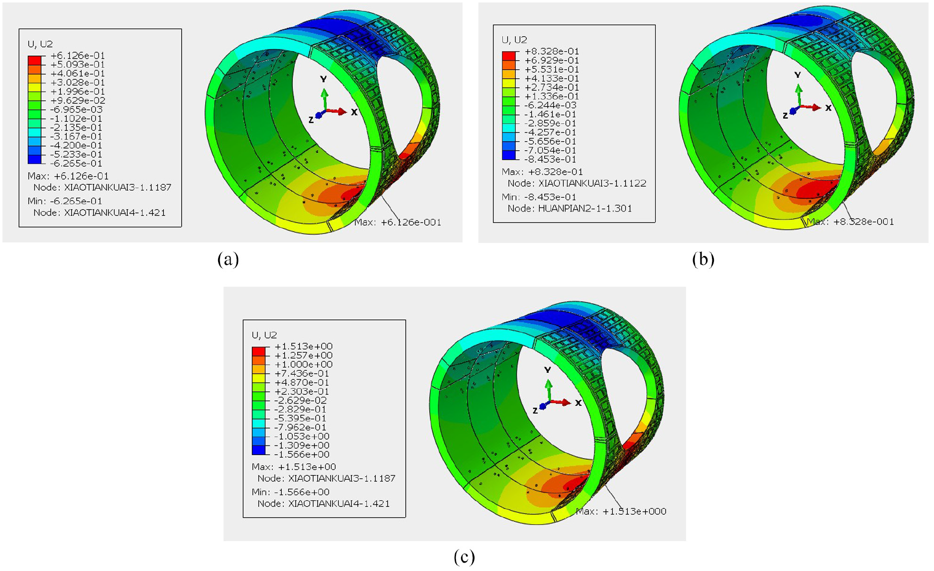
Ring displacement of rings after excavation under three loading cases: (a) design loading case, (b) unloaded case, and (c) overload case.
Corresponding calculation results of rings after excavation under three loading cases.
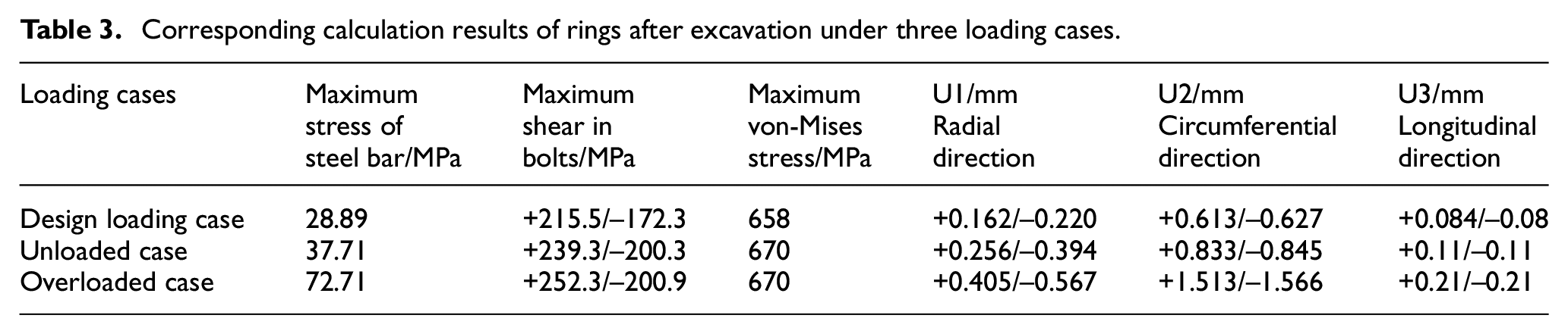
Compared with the results of specially designed rings after excavation with that before excavation, the maximum shear in bolts and the maximum von-Mises stress have slightly changed, and the circumferential deformation decreases. The reason for this is that the steel-concrete reinforced special segments are heavier than the common segments, whose gravity induces the tendency of rotation.
Analysis of results without bolt fastening
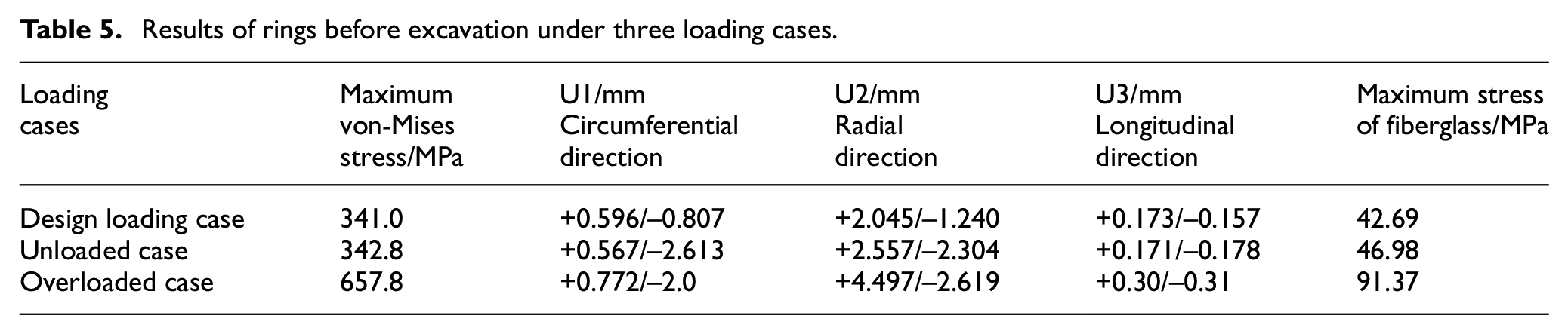
For investigating the interaction between the segments, such as friction, contact, and the effects of circumferential and longitudinal bolts on connected segments, calculation is carried out without any bolts in this section. From the nephograms of simulation results, it can be seen that the maximum stress of the segment occurs in the joint position of the steel sheet in three loading cases, and the maximum stress of the steel bar also occurs in the joint of the steel segment and the concrete segment, as indicated by the arrow shown in Figures 13 and 14. The maximum stress and maximum displacement in all directions under the three loading cases are listed in Tables 4 and 5.

Stress nephogram and maximum stress position of segment and steel cage in design loading case.
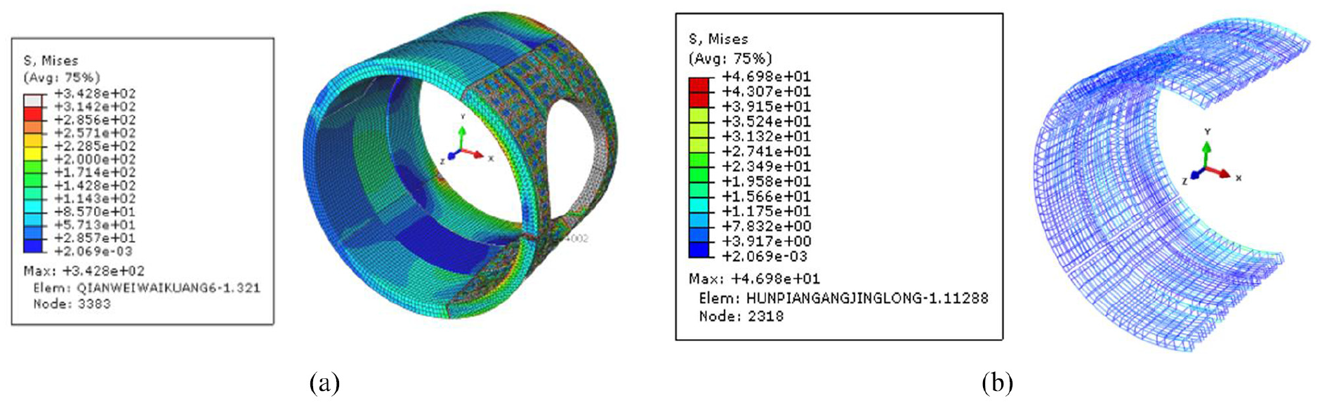
Stress pattern and maximum stress position of design piece and steel cage design sheet and steel cage.
Results of rings after excavation under three loading cases.

Results of rings before excavation under three loading cases.
According to the simulation results, there are 6–8 (1–2 fibers per corner) fiberglass bars puffed off at the four corners of the cutting block in the middle of the special segment in three loading cases. However, these fractures do not affect the overall stability and deformation of the segment.
Comparing with the analysis of model without bolts, the longitudinal connecting bolts between the crown sealing segment and the adjacent segments may be cut off. Still it is in the acceptable range of overall stability although it will affect the local failure. It can be seen that the displacement in all directions and the maximum stress of the steel bars in the model without reinforced bolts are larger than that with reinforced bolts. For tunnel segments, although the strength and stability are met to satisfy, the deformation of the segment should be as small as possible, which could prevent groundwater from leaking into the tunnel. Therefore, the fastening bolts are necessary for the connection reinforcement of the segments.
Conclusion
In this paper, the specially designed rings in the T-joint cross-connecting the main tunnel with mechanically constructed connecting channel have been simulated and analyzed under three loading cases. From the results obtained the following conclusions can be drawn.
Based on the comprehensive analysis, the strength and stiffness of the specially designed T-joint can meet the requirement at the buried depth before and after excavation. So the designed structure with special steel-concrete segments is feasible.
Locally, the reinforced fiberglass bars would be pulled off in the most critical case. It would not induce the entire failure of the segments but care should be taken and they should be monitored during the operation processing.
The maximum stress of the longitudinal curved bolts between special segments approaches to the shear strength of bolt M6.8. Therefore, it is necessary to enhance the strength grade. This improvement is closely related to whether the segments can prevent groundwater from leaking into tunnel.
The specific analysis results provide reference and basis for subsequent construction. The parametric study of this analysis will be performed in future researches.
Footnotes
Acknowledgements
The authors acknowledge the financial supports received from National Natural Science Foundation of China (No.11972203, No.11572162), 47th Scientific Research Foundation for Returned Scholars from Ministry of Education of China, the Natural Science Foundation of Zhejiang Province (LY13A020007), Ningbo Rail Transit (JS-00-SG-17003) and K.C. Wong Magna Fund in Ningbo University.
Handling Editor: James Baldwin
Declaration of conflicting interests
The author(s) declared no potential conflicts of interest with respect to the research, authorship, and/or publication of this article.
Funding
The author(s) received no financial support for the research, authorship, and/or publication of this article.