
Abstract
The increase of axle load and train speed would cause intense wheelrail interactions, and lead to potential vibration related problems in train operation. For the low-frequency vibration reduction of a track system, a multi-layer track structure was proposed and analyzed theoretically and experimentally. Firstly, the analytical solution was derived theoretically, and followed by a parametric analysis to verify the vibration reduction performance. Then, a finite element simulation is carried out to highlight the influence of the tuned slab damper. Finally, the vibration and noise tests are performed to verify the results of the analytical solution and finite element simulation. As the finite element simulation indicates, after installation of the tuned slab damper, the peak reaction force of the foundation can be reduced by 60%, and the peak value of the vertical vibration acceleration would decrease by 50%. The vibration test results show that the insertion losses for the total vibration levels are 13.3 dB in the vertical direction and 21.7 dB in the transverse direction. The noise test results show that the data of each measurement point is smoother and smaller, and the noise in the generating position and propagation path can be reduced by 1.9 dB–5.5 dB.
Introduction
Rail transit1,2 has become the first choice for citizens to travel because of its advantages like safety, punctuality, comfort, and large carrying capacity. The increase of axle load and train speed would cause intense wheel-rail interactions, and lead to potential vibration issues in train operation.3–7 To solve this problem, many researchers have done various investigations on the dynamic characteristics and damping principle of track structures. Esmaeili et al. 8 established a mathematical model of the vehicle–floating slab track interaction and they found that slab thickness has more effect on slab than rail dynamic behavior. Jin 9 investigated the dynamic response of a slab track under the action of vehicles through theoretical derivations and numerical simulations. The results showed that a larger the rail pad stiffness will increase the resonance speed to a small degree and aggravate wheel-rail resonance response at the resonance speed. Kaewunruen and Kimani 10 studied oscillation behaviors of a precast steel-concrete composite slab panel for track support, and they observed crossover phenomena that result in the inversion of the natural orders without interaction. Liu et al. 11 investigated the effects of fastener stiffness and fastener damping on the dynamic response of the track structure. They found that a higher stiffness can improve the dynamic response of the rail in the nonresonant region at a high frequency and a larger damping can greatly reduce the high-frequency vibration of the track structure. Aggestam and Nielsen 12 simulated vertical dynamic interaction between vehicle and tracks using 3D models of the slab track and running vehicle, which calculated the pressure distribution along both the longitudinal and the lateral direction. Liu et al. 13 obtained an optimal method for the slab track plate to mitigate its vibration, and experiment showed vibration level could be lowered by 8.9 dB on average in the frequency range from 20 Hz to 400 Hz. Zeng et al. 14 proposed a new low-vibration track system for a heavy-haul railway to realize ground vibration reduction. It also has lower vibration acceleration, shorter duration of vibration period, lower vibration frequency of track components.
According to previous studies, the researchers have done lots of work on the dynamic characteristics of ordinary track structures utilizing the finite element and online testing methods and put forward effective vibration reduction measures. However, the ordinary track structure can only reduce the vibration sections over the frequency range more than
For the low-frequency vibration reduction in track engineering, a multi-layer track structure is proposed in this paper and its analytical solution is derived theoretically. Then, a parametric analysis is conducted to discuss its vibration reduction performance, and a finite element simulation is established to highlight the influence of the tuned slab damper. Finally, the vibration and noise tests are employed to verify the results of the analytical solution and finite element simulation. The onsite vibration and noise tests under the normal operation conditions were carried out and results show that the insertion losses for the total vibration levels were 13.3 dB in the vertical direction and 21.7 dB in the transverse direction comparing new multi-layer track structure with ordinary track structure. And at the same time noise reduction of 1.9 dB–5.5 dB were achieved.
Multi-layer elastic damping track structure
Appraisal index
According to the action mechanism, the track structure directly bears the load from wheelsets and transfers to the foundation structure and surrounding buildings; meanwhile, the reaction of the track structure also increases the vibration of the wheels. Therefore, the wheel-rail interactions would put the track structure in the undetermined coupling vibration state. On the one hand, certain levels of vibration caused by the wheel-rail disturbance could affect the train operation quality and the life of the surrounding residents. On the other hand, the severe vibration would lead to the damage and fracture of vehicles and track components, endangering the safe operation of the train. Therefore, there are typically three objectives to reduce the vibration of track structures:
The reasonable track structure can reduce the mutual excitation between the wheel and rail, that is, the dynamic action transferred from the track structure to the surrounding ground.
The optimized parameters can reduce the first-order natural frequency of the track structure. So the ratio of the external load frequency to the natural frequency of the track structure would be greater than the critical threshold. It would achieve a specific effect of low-frequency vibration reduction.
The reduction of wheel-rail interactions can avoid fatigue and instability caused by the long-term vibration and prolong the service time of track components. For the consideration of the above aspects, the dynamic displacement transfer coefficient
Track structure
Some relevant studies5,15–17 show that dynamic vibration absorbers with sensible design play a crucial role in attenuating the vibration of specific frequency bands. According to the limitations of on-site construction conditions and the technical requirements, a multi-layer elastic track structure which consists of fastener, tuned slab damper and floating slab track, was proposed to achieve the vibration control for the specific low frequency section, as shown in Figure 1. Based on the law of energy conservation, the new track structure absorbs the track vibration energy via the additional mass and damping introduced, and therefore reduces the vibration level of the track structure. Meanwhile, by adjusting the parameters of each unit, the phase angle of the additional mass block can be opposite to that of the main system, thus reducing its low-frequency vibration.
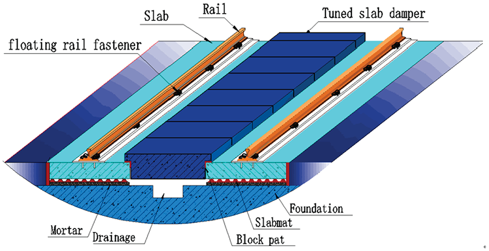
Diagram of fastener/tuned slab damper/floating slab track.
The track structure is designed as precast concrete track slabs to meet the requirements of on-site construction and maintenance. The two-way prestressed concrete frame slab is transported to the project site and fitted into a solid track structure. The middle of the track plate is hollow, as shown in Figure 2. Both the floating track slab and tuned slab damper have the same materials.

Structure of precast concrete track slabs.
The elastic elements under the track plate is a multi-layer damping rubber pad with conical studs column structure as shown in Figure 3. Because of their conical shape, the stiffness of these studs increases gradually when the vehicle load increases during the train movement. When the load becomes too heavy, the damping rubber pad would produce a small displacement to ensure the smooth operation of the train. Hence, the under plate behaves in non-linear fashion because its stiffness changes as loading changes. This design not only realizes the effect of vibration reduction, but also ensures the safety of train operation.

Damping rubber pad.
The rails are welded into the seamless type on site. The resonant floating fasteners are symmetrically arranged on each prefabricated rail plate. The rail is designed to be clamped and suspended by a special rubber wedge at the waist. This not only realizes the isolation of the rail vibration, but also provides a very low vertical stiffness. As shown in Figure 4, the mass unit of the resonant floating fastener is embedded in the rubber wedge to form a mass-spring-damping structure. So the vibration energy can be absorbed by the resonant mass unit, thus achieving the effect of controlling the vibration and noise.

Structure of floating rail fastener.
Analytical model
Considering the damping effect of the fastener, the above discussed multi-layer elastic damping track structure was simplified to a three-layer mass-spring-damping system,
18
as shown in Figure 5. For the tuned slab damper (resonant plate) fixed to the floating slab track with elastic elements, its mass is
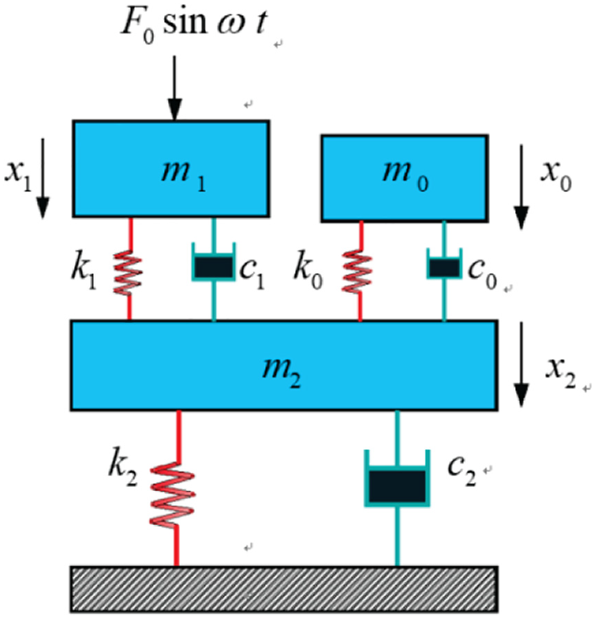
Simplified model of fastener/tuned slab damper/floating slab track.
Under the simple harmonic load

where the superscribed dot denotes time derivative, and

where
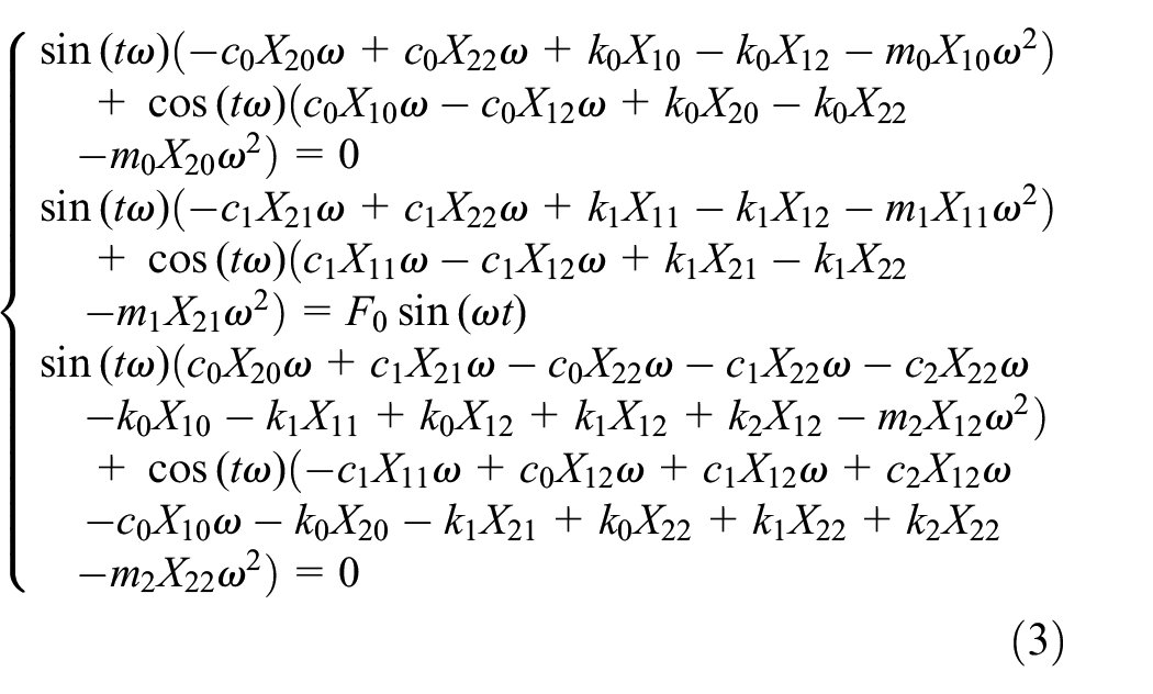
After simplification, an algebraic equation can be obtained as

where


and

Because unknown parameters
The foundation reaction force

The dynamic load transfer coefficient

For the mass

Parametric analysis
For a better understanding of the vibration reduction performance of subject multi-layer elastic damping track structure, the influential parameters were analyzed. For tuned slab damper, floating slab track, and rail, parameters16,19–22 were selected as:
Tuned slab damper
Figure 6 shows frequency response spectra of the dynamic displacement transfer coefficient
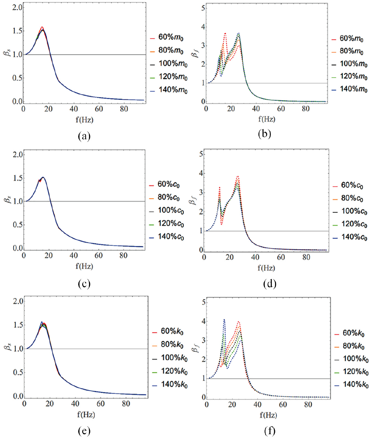
Influence of parameters of tuned slab damper on dynamic displacement/force transfer coefficients: (a)
Rail and fastener
As Figure 7 shows, rail mass

Influence of parameters of rails and fastener on dynamic displacement/force transfer coefficients: (a)
Floating slab track
Figure 8 demonstrates that mass

Impact of parameters of the floating plate on dynamic displacement/force transfer coefficients: (a)
Above analysis results have demonstrated that the parameters, that is, mass, damping and stiffness, of each part of the multi-layer elastic damping track structure model have shown different effects on the dynamic displacement transfer coefficient
Finite element simulation
Finite element model
Two cases (with or without tuned slab damper) are presented to examine the impact of tuned slab damper on the vibration reduction performance. The dynamic explicit algorithm in Abaqus is used for analysis. The finite element model of the three-layer track structure is shown in Figure 9 and its parameters are as follows:
(1) Grounding spring element (spring1) and linear spring element (spring 2) can only be used for implicit calculation, so the fastener is simulated by nonlinear axial springs. Because the nonlinear axial springs cannot customize the stiffness of each direction, the vertical stiffness is defined as
(2) The element type of track plate is C3D8R, with an average side length of 50 mm, and number of elements for each track plate is 9904. The element type of rail is B31, with a length of 62.5 mm, and the number of elements for each rail is 400.
(3) For a

Finite element model of the three-layer track structure.
A: 32.4 Hz when the wheel passes through the rail fastener;
B: 7.78 Hz when the axle passes through the rail fastener;
C: 1.2 Hz when the bogie passes through the rail fastener; The peak load applied to the rail is
(4) The incremental step is determined by the element size and the wave velocity of the materials. The minimum incremental step is
Results and analysis
The calculation time length is set to 1 s, and a total of 20 frames of field output results are output. The average CPU time required for calculation is 67,460 s, about 18 h. In each case, the time history outputs are set on the track foundation and the slab track to record the vertical acceleration. The output frequency is 10,000 Hz. Then the vertical acceleration time-history curves of the rail, track plate, and track foundation can be obtained. At the same time, the force on the slab track can be output by defining the integrated output section.
Force of track foundation
The force on the track foundation is an important parameter to reflect the damping effect of the tuned slab damper. Figure 10(a) and (b) show that the peak force acting on the track foundation can be reduced by about 60% after installation of the tuned slab damper.

Time history and spectrum of force on track foundation: (a) time history and (b) spectrum.
Vibration acceleration
Figure 11(a) indicates that the peak vibration acceleration of the track plate can be reduced by about 50% after installing the tuned slab damper. Figure 11(b) demonstrates that the maximum vibration level of the track plate can be reduced by about 13 dB with the tuned slab damper.

Time history and spectrum of vibration acceleration of track slab: (a) time history and (b) spectrum.
These data prove that the tuned slab damper can effectively reduce the force acting on the track foundation and the vibration level of the track plate when the train is running.
Online test
Test conditions
Tests were carried out on site under the normal operation condition of rail transit. Firstly, the wheel-rail safety index, track structure dynamic displacement, and damping performance of the existing DTVII fastener ordinary track were tested and analyzed. Then the ordinary track structure was replaced by the multi-layer elastic damping track and tested again under the same working conditions. Finally, the results of the two cases are compared to study the influence of the tuned slab damper on the vibration reduction performance.
As shown in Figure 12(a) and (b), the modified track structure is composed of rail, damping fastener, track plate, tuned slab damper, elastic cushion, limit structure, mortar layer, track foundation, and other structures. The parameters of the main components are as follows:
The track plate adopts prestressed concrete frame plate with a size of
The materials of both floating track slab and tuned slab damper are C40 concrete with an elastic modulus of 32.5 GPA and Poisson’s ratio of 0.2.
The track system adopts the elastic floating rail fastener with a vertical static stiffness of
The rial installed is
The elastic rubber damping pad is laid under the track plate with a thickness of 30 mm and static stiffness of
The normal operating train is type A composed of six carriages, with the bogie spacing of 15.7 m, wheelbase of 2.5 m, and designed axle load of 160 kN.

Transformation of track structure for online test: (a) transformation of ordinary track line and (b) Multi-layer track structure after transformation.
Testing methods
Vibration tests
The middle section of the rail plate was selected as the test point, and the arrangement of the sensors is shown in Figure 13(a). The specific test method23,24 is as follows:
Measuring the vertical vibration of the bottom position of the left and right rail and the lateral vibration of the waist position of the rail.
Measuring the vertical and lateral vibration in the center of the track structure.
Measuring the vertical and lateral vibration of the track plate below the rail.
Measuring the vertical and lateral vibration of the tuned slab damper.
Measuring the vertical and lateral vibration of the central panel of the bridge.

Installation of sensors for vibration test: (a) arrangement sketch of measuring point of vibration acceleration sensors and (b) site layout of vibration acceleration sensors.
The on-site sensor installation is shown in Figure 13(b).
Noise tests
A total of four noise measurement points is arranged on a viaduct. The sensor installation is shown in Figure 14. All measuring points are on the cross-sections. Four microphones are arranged at different places: at the center and bottom of the bridge, 7.5 m and 20 m away from the centerline. The latter two are 1.5 m above the top surface of the rail. The noise test points under the bridge are also 1.5 m above the ground.

Noise testing section and layout of measuring points.
Results and analysis
The tests were carried for both ordinary track structure and the multi-layer elastic damping track structures, and results are discussed as below. (1)Vibration tests
The frequency spectra of the vibration acceleration and total vibration levels25–28 are given in Table 1 and Figure 15, which confirm the significant reduction of vibration levels of new multi-layer damping track structure comparing with the ordinary track structure. As shown is Figure 15, the vertical and lateral vibrations of the ordinary track peaked at frequency range of 31.5 Hz–160 Hz. However, there is no such region for the new damping track. In Figure 15(a), the vertical acceleration in range of 6.3 Hz–20 Hz is relatively high, which is consistent with the theoretical prediction. Because it can be seen from the parameter analysis that the theoretical resonance frequency is between 6 Hz and 20 Hz. Moreover, the data of the damping track in the frequency range above 31.5 Hz are lower than those of the ordinary track, which illustrates the effect of the vibration damping track. The maximum vertical vibration level decreases by 15.9 dB from 96.0 dB (80 Hz) to 79.1 dB. The part less than 6.3 Hz may be the error of the test experiment. Actually, the frequency range of this part is very small. It occupies a relatively large space in the figure just because the x-axis is not uniform.
Total vibration level of accelerations of track foundation (Unit: dB).


1/3 frequency path spectrum of track foundation: (a) vertical direction and (b) transverse direction.
Similarly, in Figure 15(b), the maximum transverse vibration level decreases by 24.6 dB from 87.3 dB to the 52.7 dB. There is no vibration amplification in the range below the frequency 31.5 Hz. But in this range, the data of the damping track is also smaller than that of the ordinary track. There are two main reasons for this. The first is the experimental error. The second is the change of the exciting force caused by the change of support stiffness of the new track. It should be mentioned that after installing the tuned slab damper, the support stiffness of the track would also change, so the wheel-rail force would change. If the wheel-rail force becomes smaller, the response will also decrease. For example, for fasteners with lower stiffness, the wheel-rail force distribution becomes longer. So the distribution and amplitude of the excitation force for the track change greatly and the response becomes different. In Figure 15(b), the structure and stiffness of the track have a great influence on the lateral force, and it is obvious that the excitation has changed. Therefore, the damping track structure not only changes the vibration isolation frequency (resonance), but also changes the excitation force to the track.
From the vibration level data in Table 1, the insertion losses at the measuring point of the track foundation are 13.3 dB in the vertical direction and 21.7 dB in the transverse direction.
Noise measurement
Noise time history signals and background noises of four measuring points were measured. The 1/3 octave band frequency spectra are used for evaluation and analysis.
Figures 16 and 17 show the reduction of noise level at all four measurement points for new damping tracks comparing with ordinary track. The overall noise reduction is listed in Table 2, showing that the noise in the generating position and propagation path can be reduced by 1.9 dB–5.5 dB after adopting the multi-layer elastic damping track structure.

Sound pressure level spectra of noise measured at center and bottom of the bridge: (a) center and (b) bottom.

Sound pressure level spectra of noise measured at points away from the track centerline: (a) 7.5 m and (b) 20 m.
Sound pressure level of noise at measuring points (Unit: dB).

M: measured noise; B: background noise.
Conclusion
This paper reports the theoretical and experimental studies of a multi- layer elastic damping track structure, which includes analytical solutions derived theoretically, the parametric analysis conducted to verify the vibration reduction performance, the finite element simulation to highlight the influence of the tuned slab damper, as well as online tests to confirm the effectiveness of the new damping track structure in track vibration and noise reduction. The main conclusions are as follows:
The analytical solution of the damping track is obtained based on the principle of structural dynamics. Parametric analysis results have demonstrated that the parameters, that is, mass, damping and stiffness, of each part of the multi-layer elastic damping track structure model have shown different effects on the dynamic displacement transfer coefficient
As the finite element simulation indicates, after installation of the tuned slab damper, the peak reaction force of the foundation can be reduced by 60%, and the peak value of the vertical vibration acceleration would decrease by 50%. It shows that the tuned slab damper can effectively reduce the force acting on the track foundation and the vibration of the track plate when the train is running.
The vibration test results show that the insertion losses for the total vibration levels are 13.3 dB in the vertical direction and 21.7 dB in the transverse direction. Besides, the vibration is unmagnified in the low-frequency domain, and there is no significant vibration peak region for the damping track.
The noise test results showed overall noise reduction on all four measuring points. And the noise in the generating position and propagation path can be reduced by 1.9 dB–5.5 dB after adopting the multi-layer elastic damping track structure.
Compared to the classical two-layer dynamic vibration absorbers, the multi-layer elastic structure proposed in this paper can have more tunable parameters. And after optimization, better performance can be achieved.
Footnotes
Handling Editor: James Baldwin
Declaration of conflicting interests
The author(s) declared no potential conflicts of interest with respect to the research, authorship, and/or publication of this article.
Funding
The author(s) disclosed receipt of the following financial support for the research, authorship, and/or publication of this article: This work was supported by Shanghai Science and Technology Committee (STCSM) (Grant Nos. 17030501100) and Science and Technology Project of Quality Technology Supervision Bureau of Guangzhou Municipality (Grant Nos. 2019kj03).