
Abstract
To improve the stability and accuracy of non-circular gear transmission, a beveloid non-circular gear transmission scheme was developed to reduce the meshing impact and achieve backlash adjustment. When using the beveloid rack as the medium, the instantaneous contact line of the beveloid non-circular gear pair was shown to be a straight line, and the tooth surface was shown to be a ruled surface based on the transmission relationship between the rack centerline and the non-circular pitch curve. The zero-modification method was employed to develop the beveloid non-circular gear. Further, the generation method for the tooth profile of the modified non-circular gear was reviewed, and a digital solid model was developed for the beveloid non-circular gear. The physical contact simulation method was used to analyze the meshing backlash, and the influence of the axial displacement adjustment on the meshing backlash of the gear pair was obtained. By considering a pair of beveloid elliptic gears as an example, machining and transmission experiments were conducted, with results showing smooth gear-pair meshing and the anticipated backlash adjustment effect.
Introduction
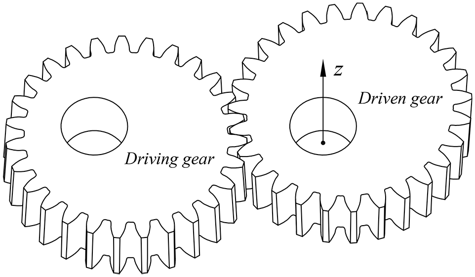
A non-circular gear exhibits a non-linear displacement relationship via meshing motion. Further, it exhibits a compact structure and large carrying capacity in its transmission design. Currently, the problem of pitch curve1,2 and tooth profile design3–5 of a non-circular gear can be successfully addressed, with many relevant applications having been developed. For example, Mundo et al. 6 and Dooner 7 applied a combination of non-circular gears and a five-bar mechanism. Ottaviano et al. 8 and Terada et al. 9 combined non-circular gears with groove cams. Mundo 10 and Zheng et al. 11 discussed the gear train design problems; whereas Karpov et al. 12 applied non-circular gears to transmission devices for improving the resonance of gear mechanisms. Okada and Takeda 13 applied non-circular gears to hopping robots, and their jumping heights were considerably better than those of robots with circular gears.
Meshing backlash is a problem that must be addressed when considering the transmission design of a noncircular gear for practical applications. Because a noncircular gear exhibits nonlinear motion, the rotational speed of the driven gear changes when the driving gear is rotated at a constant speed. Further, the direction of the rotational torque received by the driven gear frequently changes because of the meshing action. At this point, a series of problems, such as a decrease in the accuracy of the driven gear angle, meshing shock and noise, and diminished life of the gear pair, can be observed when there is an inappropriate backlash between the nonworking tooth surfaces of the meshing teeth. Until now, very few studies have investigated the meshing backlash control of noncircular gear pairs.
Beveloid gears have been developed in the field of fixed-speed ratio transmission. The gear pair can adjust the meshing backlash by axial relative displacement by linearly changing the modification coefficient of each section along the direction of the gear axis; this is suitable for transmission with precise transmission requirements. He and Wu 14 studied the meshing principle of involute conical gears and proposed a bevel gear design method to achieve appropriate installation parameters. Zhu et al.15,16 used the approximate line contact condition to construct the meshing model of beveloid gear transmission and studied the geometric design and meshing characteristics. Liu et al.17,18 studied the undercut problem associated with beveloid gears, and Wu et al. 19 studied the tooth surface contact and bearing characteristics of the beveloid gears. Herein, the beveloid design method is applied to control the meshing backlash of noncircular gear transmission.
This paper is structured as follows. In Section 2, the transmission feasibility of a beveloid noncircular gear pair and the applied design with backlash adjustment capability are discussed. In Section 3, the meshing principle of a beveloid noncircular gear and types of instantaneous meshing lines and gear-tooth faces are reviewed. The tooth profile generation of zero-modification noncircular gears and the tooth face modeling of the beveloid noncircular gears are discussed in Section 4. In Section 5, the meshing backlash of the beveloid noncircular gear pair is presented, whereas the examples of machining and transmission experiments are presented in Section 6, based on which the tooth surface contact and backlash adjustment characteristics can be analyzed.
Feasibility analysis of transmission
The premise of beveloid design for noncircular gears is to design the gear shape of each section in the gear axis direction when ensuring that the center distance of the gear pairs in each section and the transmission ratio remain consistent. Wu et al. 20 indicated that noncircular gears can be designed for zero modification, that is, the modification coefficient of the gear pair is equal in magnitude but opposite in sign, and that the transmission center distance remains unchanged. Using the zero modification design method, the beveloid noncircular gear can be constructed and the modification coefficient of the driving gear can be changed from −x1 to x2 along the gear axis direction, whereas the driven gear can be changed from x1 to −x2 along the gear axis direction. Thus, both the driving gear and the driven gear have a noncircular cone shape and equal center distance, and equal gear ratio transmission can be realized in each section of the axial direction.
Tan et al. 21 discussed the nonzero modification method of noncircular gears. Because of the noncircular feature of the pitch curve, nonzero modification requires different modification coefficients at different polar angular positions of the pitch curve when ensuring that the gear ratio remains constant. Nonzero modification will change the center distance. Under the constraint of new center distance, the variation laws of the modification coefficient of the gear pair in each section must be identical to ensure that the gear ratio remains unchanged. This makes it impossible to construct a modification law that changes sequentially in the axial direction. Therefore, the design method of the beveloid noncircular gear must adopt the zero modification method to design the modification coefficient of each section in the axial direction.
The teeth of noncircular gears are distributed on the pitch curve, that is, the initial position of the tool will affect the tooth profile of all the teeth of the noncircular gear when the rack tool is used for envelope machining. For helical noncircular gears, there is a difference in gear-tooth distribution in the tooth profile of each section along the direction of the gear axis, which cannot satisfy the condition of continuing the transmission based on the relative motion in the gear axis direction. Therefore, the beveloid helical noncircular gear cannot adjust the backlash. A beveloid spur gear should be used when considering the backlash adjustment capability.
The outline of a beveloid noncircular gear pair designed by the zero modification method is presented in the following figure.
As shown in Figure 1, the gear pair has a non-conical shape, where F0, F1, and F2 are three sections of the gear pair in the axial direction. The F0 section exhibits standard noncircular gear transmission, and the F1 and F2 sections are zero-modification noncircular gear pairs; the modification coefficients are ±x1 and ±x2. From the F1 section to the F2 section, a linear relation can be observed between the modification coefficients of each section of the gear pair. By subdividing the gear pair into an infinite number of small sections in the axial direction, each of these sections can be considered as a pair of zero-modification noncircular gear pairs. Because the zero-modification noncircular gear pair satisfies the transmission requirements, the beveloid noncircular gear pair obtained using the combination satisfies the transmission condition.

Schematic of a beveloid non-circular gear pair.
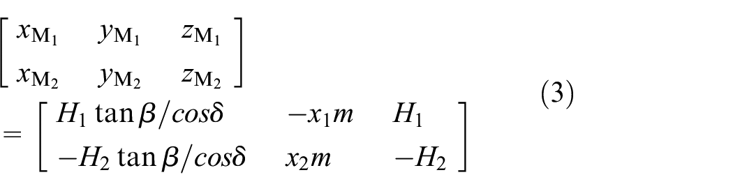
The transmission backlash of the beveloid noncircular gear pair can be adjusted by fine-tuning the axial relative position of the driving gear and the driven gear. As shown in Figure 1, the gear pair is in the zero-backlash meshing state. At this time, the driven gear can be moved by distance Δs in the direction of the F1 section so that backlash occurs between the meshing tooth faces of the noncircular gear pair. Thus, the tooth thickness of each sectional tooth shape of the driven gear engaged with the driving gear is observed to decrease when compared with that of the zero-backlash meshing state, thereby adjusting the transmission backlash. Let the gear modulus be m, the distance from the F1 section to the F2 section be H, and the tooth profile angle of the rack cutter be α. According to the formation principle of the zero-modification noncircular gear-tooth profile, the change value Δjn of the tooth surface normal gap caused by the displacement of the driven gear can be obtained as follows:

Meshing principle of a beveloid non-circular gear
Geometric definition of tooth blank and tool rack
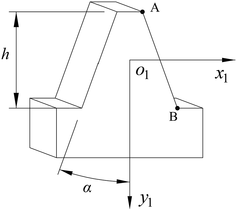
A model of the beveloid helical rack was constructed to facilitate comparison of the tooth profile characteristics of the beveloid noncircular gear and the helical noncircular gear. A geometric definition model of the variable-tooth-thickness helical rack is shown in Figure 2. The middle points of the tooth thickness of the front and rear end-face profiles of the rack are defined as points M1 and M2, respectively, and the distance between the two points in the z1 axis direction is H. The angle between the projection line of the line segment M1M2 in case of plane x1o1z1 and the z1 axis is defined as β, which is the helix angle of the noncircular gear, whereas that between the projection line in plane y1o1z1 and the z1 axis is δ. The coordinate system S1 (o1-x1y1z1) is fixed to the rack and its coordinate origino1 is located on the online segment M1M2, whereas the rack side–tooth surface defined by points A1, B1, B2, and A2 is defined as Σ1.

Beveloid helical rack model.
In Figure 2, the sections of the rack parallel to plane x1o1y1 have identical shapes, but the respective tooth sections have positional differences in the x1andy1 axis directions. Let the plane x1o1y1 have a cross section of rack R0 parallel to plane x1o1y1, and let the section passing through point M1be R1. The section parallel to surface x1o1y1 and passing through point M2 is R2, and the distances between the sections R1 and R2 and section R0 are H1 and H2, respectively. Section R1 is moved by distance mx1 in the positive direction of the y1 axis with respect to R0, and section R2 is moved by distance mx2 with respect to R0 in the negative direction of the y1 axis.
Therefore, the tooth shape corresponding to section R0 can be presented as follows.
As shown in Figure 3, the tooth profile corresponding to section R0 is defined as a standard rack shape, where h is the tooth height, α is the tooth profile angle of the rack, and the coordinate points A and B are expressed as follows:

According to the geometric relation shown in Figure 2, the coordinates of points M1 and M2 can be obtained as follows:
Rack profile obtained using the plane x1o1y1.
According to equations (2) and (3), the coordinates of the points A1, B1, A2, and B2 can be obtained as follows:
Let the equation of plane Σ1 be f1(x1, y1, z1) = 0; this equation can be solved based on the coordinates of points A1, B1, and A2, as shown in the following formula:

where a, b, c, and d are constant terms and can be given as follows:

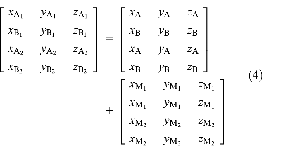
A beveloid noncircular gear blank model is presented in Figure 4. The coordinate system S2 (o2-x2y2z2) is fixed to the gear blank, the plane x2o2y2 coincides with the F0 plane in Figure 1, and the z2 axis coincides with the rotation axis of the gear blank. The plane passing through the z2 axis perpendicular to the x2o2y2 plane intersects with the outer circumferential surface of the gear blank. The angle between the intersection line and the z2 axis is defined as δ = atan [2(x1+x2)m/H].

Beveloid non-circular gear blank model.
Coordinate system transformation of tooth blank and tool rack
The motion coordinate system of the rack pitch line and the non-circular pitch curve is presented below.
As shown in Figure 5, S(o-xyz) is a fixed coordinate system, and S1(o1-x1y1z1) is fixed to the rack and S2(o2-x2y2z2) is fixed to the gear blank. The positional relation of S1, S2, rack, and gear blank is shown in Figures 2 and 4. At the initial position, point o1 coincides with o and the coordinate axis y2 coincides with y. The rack moves to the right by distance l when the gear blank is rotated through angle ψ in a clockwise direction. The polar radius and polar angle corresponding to the tangent point P are r and φ, respectively, and μ is the angle between the polar radius and the tangent.

Motion coordinate system of gear blank and rack.
The transformation of the coordinate system S2 to S1 can be given as follows:

where,

The transformation matrix

Contact line and tooth surface solution
According to the basic theorem of gear meshing,
22
at a certain meshing instant, the common normal face Σ2 of the rack tooth surface and gear-tooth surface at the tangent position will pass through the meshing momentary axis zP. The zP axis is a straight line passing through point P and is coplanar and parallel to the z-axis. Let the unit vector of the zP axis be

In the condition in which point P is located on plane Σ2 and the coordinates of point P are observed in the coordinate system S1, the equation of the Σ2 plane can be obtained as follows:

According to equations (5) and (11), the parametric equation of the contact line LT of the rack and the gear in coordinate system S1 can be solved. Let z1 = 0;then,the intersection coordinates (x10, y10, z10) of the contact line LT and plane x1o1y1can be gained as follows:

The direction vector

According to equations (12) and (13), the parameter equation of contact line LT can be obtained as follows:

where
The coordinates of the contact line LT are transformed from the coordinate system S1 to S2, and the tooth surface equation of the non-circular gear can be obtained. The tooth surface equations obtained by equations (9) and (14) are expressed as follows:

By analyzing equations (6), (9), and (15), the components of the noncircular gear-tooth surface coordinate equation were linear functions with respect to parameter t at the moment when the rack and the noncircular gear meshed; thus, the tooth surface of the beveloid noncircular gear was a ruled surface.
Calculation example of the meshing line
The following is an example of a beveloid ellipse gear and a rack. The design parameters are shown in Table 1.
Design parameters of the beveloid ellipse gear.

Note: The coefficients ha* and c* are the habitual expression of gear parameters, which is difference from the addendum symbol ha and the tip clearance symbol c.
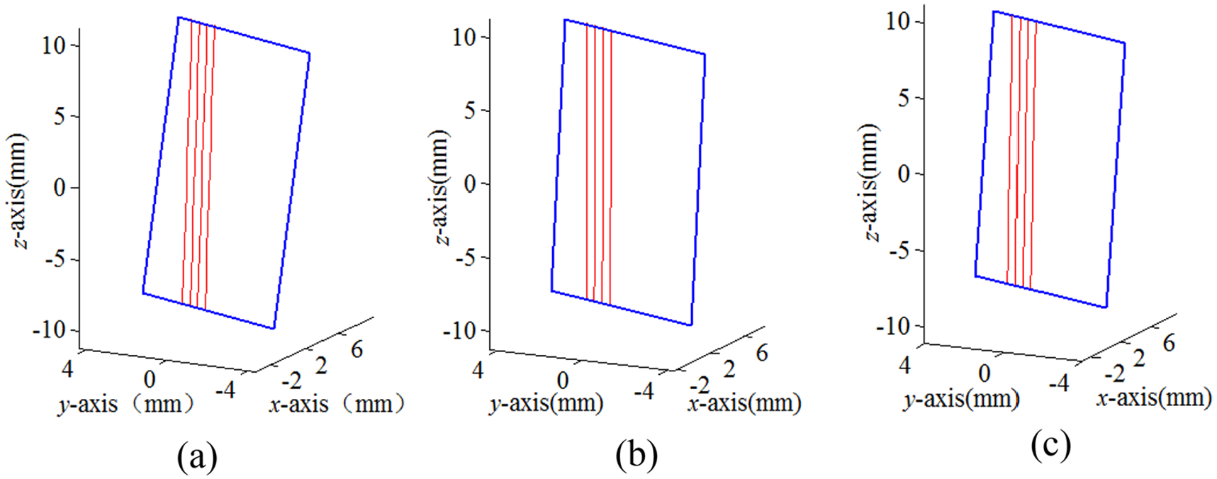
The meshing line of the beveloid helical non-circular gear obtained according to the above parameters can be observed on the rack tooth surface, as shown in Figure 6(a). Let the helical angle β = 0, and the meshing line of the beveloid spur non-circular gear be obtained as shown in Figure 6(b). Let the modification coefficient x = 0, and the meshing line of the non-circular helical gear can be obtained as shown in Figure 6(c).
Computational analysis of meshing lines
When comparing Figure 6(a)–(c), the meshing lines of the beveloid spur (or helical non-circular gears) were observed to have the meshing line characteristics of the helical non-circular gear. In case of a beveloid helical gear, the meshing line was closer to the helical gear. However, it was replaced by a helical noncircular gear in case of transmission applications because the beveloid helical gear was not suitable for backlash adjustment by axial misalignment of the gear pair. The beveloid spur noncircular gear exhibited the function of backlash adjustment as well as the characteristics of a helical noncircular gear, reducing the meshing impact.
Tooth surface model construction
Implementation of zero-modification drive
The meshing pattern of the zero-displacement non-circular gear pair that introduces the media rack is presented in the following figure.
As shown in Figure 7, the rotation center of the driving gear and the driven gear are o1 and o2, respectively, and their pitch curves are pc1 and pc2, respectively. The two pitch curves are tangential to point P. The center line tl0 of the media rack is the common tangent of the two pitch curves, and line nl is the common normal line at point P. In the meshing state, the media rack is biased by distance Δb in the common normal direction, the position of the center line of the rack is changed from tl0 to tl1, and the pitch curves of the gear pair remain unchanged. If at each position of gear pair meshing, the media rack is offset by distance Δb along the normal direction of the tangent point of the pitch curve, the process can be regarded as a meshing process of the zero-modification noncircular gear pair and the media rack.

Zero-modification implementation process.
During the transmission process of the zero-modification noncircular gear pair, the tooth thickness of the driving gear and the driven gear changes because of the deviation of the rack along the normal direction of the pitch curve.
To ensure that the transmission tip clearance of the noncircular gear pair remains unchanged, the addendum curve and the root curve of the gear pair will also become equidistant with the previous curve, with a distance of Δb.
Based on the principle of the graphic method4,5 and considering the offset of the rack at each meshing position, the resulting profile-shifted noncircular gear is shown in Figure 8.

Profile-shifted non-circular gear.
Tooth surface modeling
The noncircular characteristic of the pitch curve results in its profile data having different functions at different locations of the pitch curve. In addition, the tooth profile data must consider the influence of tooth distribution, that is, the change in the position of one tooth will affect the tooth profile data of all teeth.
The meshing process of the beveloid noncircular gear and the rack can be regarded as the meshing of the profile-shifted noncircular gear and the rack in each section along the gear axis. Accordingly, the following method can be used to model the tooth surface of the beveloid noncircular gear.
Constructing a beveloid rack model and letting the rack pitch plane and the noncircular gear pitch surface roll purely. In this process, the tooth blank and rack are subjected to a Boolean difference operation, obtaining a preliminary model of the beveloid noncircular gear.
Layering the obtained preliminary model, obtaining multilayer cross-section data, and acquiring and fitting the effective points of the tooth profile data of each layer.
Based on the tooth profile data of each layer, the surface configuration of each tooth groove is obtained by surface stakeout, formulating a solid model of a beveloid noncircular gear.
The graphical representation of the process is shown in Figure 9.

Tooth surface modeling of the beveloid non-circular gear.
Transmission backlash analysis
Non-circular gear backlash
Backlash must be considered when designing a noncircular gear pair. Reasonable backlash is considerably important for improving the stability and motion accuracy of transmission, reducing the meshing noise, and ensuring good lubrication conditions. In the specific design of the gear pair, a suitable backlash must be reserved for the gear pair under static and measurable conditions.
The circumferential backlash jt and normal backlash jn must be primarily observed when considering the meshing backlash of the noncircular gear pair. The circumferential backlash jt is the value of the sway arc length of the driven gear at the tangent point of the pitch curve when the noncircular driving gear is fixed at a certain position. This value majorly affects the transmission precision of the noncircular gear pair. The normal backlash jn is defined as the minimum distance between the nonworking tooth surfaces when the working tooth surfaces achieve contact. This value is primarily used to maintain the certain viscosity of the lubricating oil and compensate for the deformation of the gear teeth under stress and heat. The backlash of a noncircular gear can be illustrated as follows.
As shown in Figure 10, point P is the pitch point at a specific moment. When the driving gear is fixed, the driven wheel is pressed against the driving gear in the counterclockwise direction and the minimum distance between the nonworking tooth surfaces represents normal backlash jn. At this moment, the driven gear moves in the reverse direction. Thus, the nonworking tooth surface is in a pressed state and the arc length over which point P moves is circumferential backlash jt. The line segment PA is perpendicular to o1o2, the length is jt, the line segment PB is parallel to the common tangent direction of the pitch curves, the line segment PC is parallel to the normal direction of the tooth profile, and the length is jn. Then, the relation between jt and jn can be expressed as follows:

where μ is the angle between the polar radius and the tangent, and α is the tooth angle of the rack cutter.
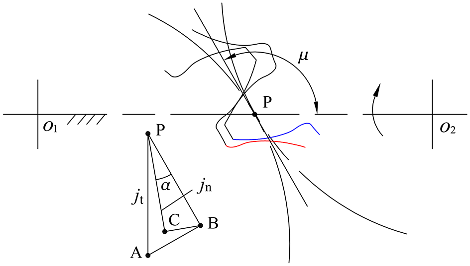
The backlash of a non-circular gear pair.
Simulation calculation of backlash
In case of noncircular gears, it is difficult to calculate the tangency, separation, and intersection of the tooth surface using an analytical method due to the heterogeneity and complexity of the tooth surface. In this paper, a simulation calculation method was adopted for the meshing backlash.
Based on the development of the tooth surface model of the beveloid noncircular gear, for the gear pair at a certain meshing position, the driving gear was placed in a fixed state and the driven gear approached the driving gear clockwise and counterclockwise in a specific angular step. In the approaching process, when each step of the driven gear was advanced, a Boolean difference could be observed between the driving gear and the driven gear to determine whether the driving gear volume changed. If a change was observed, the stepping process of the driven gear in the direction was terminated, and the stepping process was performed in the opposite direction from the initial position.
At each meshing position of the gear pair, the sum of the angles at which the driven gear was rotated clockwise and counterclockwise with respect to the initial position was multiplied by the polar radius of the driven gear at the meshing position, and the circumference backlash of the meshing position was obtained. By considering the elliptical gear defined by the parameters in Table 1 as an example, the backlash simulation calculation was conducted under the standard installation center distance condition. A digital model of the beveloid spur noncircular gear pair is shown below.
As shown in Figure 11, the driven gear was moved by 1 and 2 mm in the z-axis direction toward the gear pair backlash-increasing direction. When the driving gear rotated by 180° counterclockwise from the position at which the polar angle was zero, 11 points were uniformly obtained for calculating the backlash. The step angle of the driven gear was taken as 0.001°, and the obtained circumferential backlash variation characteristics are shown below.
The model of the beveloid spur non-circular gear pair.
As shown in Figure 12, when the axial offset Δs of the driven gear relative to the driving gear increased from 1 to 2 mm, the circumferential backlash of the driven gear was observed to increase. The proportional relation of the numerical changes was approximately equal to the proportional relation of the axial offset.

The simulation results of circumferential backlash.
According to the data presented in Figure 12 and equation (16), the calculated normal backlash change diagram can be presented as follows.
As shown in Figure 13, the beveloid spur gear was used for transmission. The normal backlash obtained using the gear pair axial misalignment method exhibited improved consistency at different tooth positions of the pitch curve. When Δs = 1 mm, the mean value of normal backlash jn was approximately 0.012 mm. When Δs = 2 mm, the mean value of normal backlash jn was approximately 0.025 mm and the numerical calculation result was consistent with equation (1).

The calculation results of normal backlash.
Experimental analysis
Computer numeric control machining
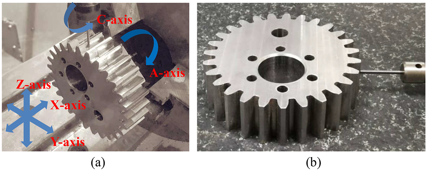
The non-circular gears manufacturing methods include hobbing, 23 shaping, 24 milling, 8 and additive manufacturing. 25 According to the analysis in Figure 6, the tooth surface of the beveloid non-circular gear was characteristic of a helical non-circular gear, and the milling method must be implemented on a multi-axis machine. In this paper, a four-axis linkage machining center was used to mill the beveloid non-circular gear, as shown in Figure 11. In order to test the manufacturing accuracy, Hexagon’s three-coordinate measuring machine was used to test the manufacturing error of the tooth surface. A series of discrete measuring points were taken on the tooth surface to evaluate the deviation from the measuring point to the theoretical tooth surface. The machining and inspection process is shown as Figure 14.
The milling and inspection process.
As shown in the Figure 14(a), a ball-surface milling cutter was used for milling the tooth surface. The high-speed rotation of the tool in the C-axis direction formed a cutting motion. The rotary motion of the gear blank in the A-axis direction and the movement of the tool in the X, Y, and Z-axis directions formed a four-axis linkage relation. For the beveloid elliptical gear, the driving gear and driven gear were identical, and their taper directions opposed each other during assembly. As shown in the Figure 14(b), through the coordinate collection of the discrete points on the tooth surface and the comparison with the theoretical tooth surface, the manufacturing error of the discrete points on the tooth surface of the machined beveloid elliptical gear was ±0.003 mm.
Normal backlash test
The pressing lead wire method was used to practically measure the normal backlashto verify the influence of the axial relative displacement of the beveloid noncircular gear pair on normal backlash. The driven gear was moved 2 mm in the direction of the rotation axis relative to the driving gear, and a lead wire with a diameter of 0.1 mm was used to perform the test, as shown below.
As shown in Figure 15(a), the three sections of lead wire were arranged on the surface of the tooth groove; then, the gear teeth were allowed to enter the tooth groove for meshing. The lead wires distributed on both sides of the tooth groove were flattened, and the sums of the thicknesses of the lead wires on both the sides were considered as the normal backlash. The experimental result is shown in Figure 15(b), where the normal backlash of different crosssections in the gear axis direction ranged from 0.024 to 0.029 mm, which was consistent with the analysis result shown in Figure 13.

The test of normal backlash.
Conclusion
In this study, a beveloid noncircular gear pair scheme was designed based on the design concept of a beveloid cylindrical gear to improve the transmission accuracy and stability of noncircular gears. The observations of this study are as follows.
The noncircular gear pair can adopt the zero modification method to realize the beveloid design. The beveloid helical noncircular gear is not suitable for backlash using the axial displacement method. However, the beveloid spur noncircular gears can be used for backlash adjustment.
The instant contact line of the tooth surface of the beveloid noncircular gear pair is a straight line, and the tooth surface type is a ruled surface. The tooth surface of the beveloid noncircular gear exhibited the characteristics of a helical noncircular gear, which can reduce the meshing impact.
In terms of adjusting the backlash, the beveloid noncircular gear pair can achieve almost similar normal backlashes at different positions on the pitch curve via relative axial displacement. The proportional relation of the numerical change of normal backlash is equal to the proportional relation of the axial relative displacement.
The tooth surface geometric model obtained based on the simulation cutting principle can satisfy the required transmission requirements. The effectiveness of backlash adjustment can be verified via computer numeric control machining experiments and pressing lead wire analysis.
Footnotes
Handling Editor: James Baldwin
Authors’ contributions
JH and LX was in charge of the whole trial; DL wrote the manuscript; XT assisted with design and experiment analyses. All authors read and approved the final manuscript.
Declaration of conflicting interests
The author(s) declared no potential conflicts of interest with respect to the research, authorship, and/or publication of this article.
Funding
The author(s) disclosed receipt of the following financial support for the research, authorship, and/or publication of this article: This work was financially supported by the National Natural Science Foundation of China (Grant Nos. 51875161 & 51575154).
Availability of data and materials
All data generated or analysed during this study are included in this published article.