
Abstract
The single-tube heat transfer experiment rig is composed of various equipment and devices connected through pipelines. This paper adopts Siemens PLC as the main controller and cooperates with WEINVIEW HMI MT6000 series HMI to design the experimental measurement and control platform of a single-tube heat transfer experiment rig. In the single-tube heat transfer experiment measurement and control platform, the PLC communicates with the HMI through an RS-485 cable, and the HMI can display the experimental data changes in real-time and has a separate control interface. The-single tube heat transfer experiment measurement and control platform is safe and reliable, with functions such as real-time monitoring and acquisition, real-time fault alarm, parameter change, and remote control, which simplifies the steps of data acquisition, reduces the difficulty of equipment control, and realizes the automatic acquisition and control.
Introduction
Programmable Logic Controllers (PLC) is a special microprocessor-based digital computer, 1 and it receives electrical signals from sensors and manual inputs, and periodically transmits control commands to the actuator. 2 It has a wide range of applications. 3 PLC mainly writes programs and applies the program to its internal hardware to intelligently control the equipment. Besides, it reduces the price of advanced and complex control systems. 4 Siemens provides researchers with a large number of operating terminals. 5 Human Machine Interface (HMI) is defined as the utility of equipment marks and tools related to the correct execution of specific work operations, 6 which can display information and collect operating commands from researchers. 7 It is a terminal display device that usually displays the status and control process of the PLC in a graphical manner. 8 Improving interactions across many platforms, systems, and business areas and is seen as a critical factor. 9
In recent years, researchers in various fields have conducted application and research analysis on the various characteristics of the combination of PLC and HMI. Yu and Wen-qing 10 designed a gas distribution device combined with PLC and HMI to realize the continuous adjustment of the output flow of combustible mixed gas and the proportion of combustible gas. José Carlos et al. 11 designed a well water discharge monitoring platform based on PLC and HMI, enabling researchers to detect system faults through programmed alarms during the experiment, and quickly resolve them through real-time alarms. Li et al. 12 developed a measurement and control system for helium liquefier based on PLC and HMI to achieve specific values of the outlet temperature of the secondary turbine and the temperature before the throttle valve. Smith et al. 13 used PLC and HMI combined with Visual Basic.NET programming language to develop an electric vehicle system framework scheme for light commercial enterprises and verified that the scheme was economical and flexible through the audit. Su et al. 14 designed a thermal simulator control system using PLC and Siemens SINAMICS V90PN servo control system to achieve high-speed data acquisition and data analysis and processing, as well as precise positioning and rapid-response control.
The single-tube heat transfer experiment rig can study the heat transfer characteristics of different refrigerants in the test section and has been widely used. Its working process is: the measured refrigerant starts from the reservoir and is pumped into the preheater preheat, then enters the test section for experiments, and finally flows into the reservoir through the condenser.15,16 According to the different needs of the experiment, the type of single-tube used in the test section can be smooth round tube, 17 micro-fine tube, 18 and rectangular tube,16,19 and the direction can be horizontal15,16 and vertical.19,20 Therefore, the flow characteristics and heat transfer characteristics of refrigerants in different tube types can also be studied. The experiment rig contains various types of equipment and devices. Researchers complete the data collection by controlling the equipment and adjusting the equipment. However, manual control of each device not only makes the operation tedious and inefficient, but also the personal safety of researchers cannot be guaranteed, and the integrity of the data chain obtained during the data collection process is low.
According to the researches of the above scholars, the operation platform designed by combining PLC and HMI can not only realize the control and adjustment of experimental equipment, real-time animation processing, and monitoring of data changes. It can also meet the diverse and unique energy efficiency requirements of the users. However, the above studies mostly focused on the analysis of experimental results after the experimental rig was designed and applied to the actual process. The research content of the design phase of the application of the combination of PLC and HMI is rarely introduced, and the application of the combination to the single-tube heat transfer experiment rig is also rare. Therefore, this paper designs a single-tube heat transfer experimental measurement and control platform based on the principle and operating process of the single-tube heat transfer experiment rig. The platform is based on PLC as the main controller, and uses STEP7 software to establish a control logic for the single-tube heat transfer experiment rig, and cooperates with WEINVIEW HMI MT6000 series HMI to realize human-computer interaction with researchers. So as to achieve the purpose of control and data collection of the experimental rig. This platform realizes the researcher’s automatic adjustment and control of the start and stop of the experimental equipment, the switching of large and small range flow meters, the frequency of the water pump, and the power of electric heating. Besides, the data collected during the experiment can be displayed in the HMI in real-time, and all the data obtained after the experiment can be saved to the computer, which facilitates the researcher to further process and analyze the experimental data.
Principle and operation process of single-tube heat transfer experiment rig
The system schematic diagram of the single-tube heat transfer experiment rig is shown in Figure 1, which includes the refrigerant circulation system and the water circulation system. The water circulation system includes the preheating treatment circulation circuit, the test section water circulation circuit, the condensing treatment circulation circuit, and the subcooling treatment circulation circuit. The preheating treatment circulation circuit, the condensing treatment circulation circuit, and the subcooling treatment circulation circuit share the same glycol cryogenic tank, which reduces the cost of the experimental equipment and the area of the experimental device. In the refrigerant cycle, the subcooler is located in front of the diaphragm metering pump, to ensure that the refrigerant entering the diaphragm metering pump remains supercooled, and to prevent the refrigerant from flashing steam when it passes through the inlet and outlet valve groups of the diaphragm metering pump. Besides, a pulsation damper is installed behind the pump, which can eliminate the pulsation of the refrigerant and reduce the fluctuation of data collection. The equipment and apparatus for the single-tube heat transfer experiment rig are shown in Table 1. Among them, the range of refrigerant flowmeter GR1 in the refrigerant cycle is 0–0.6 kg/min with an accuracy of 2.0%, and the range of refrigerant flowmeter GR2 is 0–5 kg/min with an accuracy of 2.0%, and refrigerant flowmeters GR1 and GR2 are in parallel relationship with each other. During the experiment, refrigerant flowmeters GR1 and GR2 can be switched according to the actual situation to ensure more accurate data measured in the experiment. Platinum resistance has the advantages of high measurement accuracy and good withstand voltage performance. Therefore, the temperature collection device is the platinum resistance throughout the experiment, its range is −10 to 60°C, and the accuracy is ± 0.1°C.

System schematic diagram of the single tube heat transfer experiment rig.
Equipment and apparatus for single tube heat transfer experiment rig.

The operation process of the single-tube heat transfer experiment rig is shown in Figure 2. The diaphragm metering pump first extracts the refrigerant liquid from the accumulator, eliminates the pulsation of the refrigerant liquid through the pulsation damper, and measures the mass flow rate of the refrigerant by the mass flowmeter. The refrigerant passes the plate heat exchanger HE2 for heat exchange and enters the test section. In the test section, the refrigerant and the circulating water are fully exchanged and evaporated. The refrigerant at the outlet of the test section is in a vapor state, and is re-cooled into a refrigerant liquid through the plate heat exchanger HE3 and enters the liquid reservoir. The experiment rig can perform heat transfer experiments of different refrigerants, and the test section of the experiment rig can be replaced with a tube-type according to the needs of the experiment so that the experimental data corresponding to the tube type can be obtained for comparison and analysis.

The operation process of the single-tube heat transfer experiment rig.
Design of measurement and control platform for single-tube heat transfer experiment
According to the system schematic diagram and operation process of the single-tube heat transfer experiment rig, the data to be collected includes temperature, pressure/differential pressure, and flow rate, and equipment such as water pumps and electric heating must be controlled. Therefore, the single-tube heat transfer experimental measurement and control platform based on PLC and HMI is shown in Figure 3. It is mainly composed of five parts: data acquisition, executable part, PLC controller, touch screen, and monitor upper computer. Among them, PLC is used as the main controller, which is responsible for processing the data signals of each measuring point of the experiment rig and controlling the equipment, transmitting data and equipment status to the upper computer through the communication line, and receiving instructions input by the researcher on the upper computer. Touch screen and configuration software, as the upper computer measurement and control system, can perform online real-time human-computer interaction.

Design of the single tube heat transfer experimental measurement and control platform.
After the design of the components of the single-tube heat transfer measurement and control platform is completed, the opening process of the platform is designed to ensure that the subsequent design proceeds step by step. The running process design of the single-tube heat transfer experimental measurement and control platform is shown in Figure 4.

The running process of the single-tube heat transfer experimental measurement and control platform.
It is also very important to design an alarm device in the single tube heat transfer measurement and control platform. It is designed to issue an alarm when a fault is detected, 21 that is, as a layer of protection to prevent accidents caused by process disturbances. 22 When the equipment is abnormal during the experiment, an alarm bell can be issued in time. The schematic diagram of the alarm signal is shown in Figure 5. Test electric heating, front-end electric heating, and water tank heating are normally closed, if they occur over temperature or low flow rate, the sensor set on the electric heating will be disconnected and transmitted to the program to trigger the alarm bell; the inverters of the diaphragm metering pump, test water pump, and front water pump are in the normally closed state, if they are disconnected, they will be transmitted to the program and the alarm bell will be triggered; the chiller and the circulating water pump are open, if the chiller fails or the circulating water pump overcurrent, the sensor will be closed and the alarm bell will be triggered.

Schematic diagram of the alarm signal.
PLC control system design
The input and output modules of the PLC, that is, I/O modules, can be divided into fixed and modular. 23 This platform uses a modular type, and a rack is used to fix the I/O modules as shown in Figure 6. Therefore, the type and number of I/O modules can be changed.
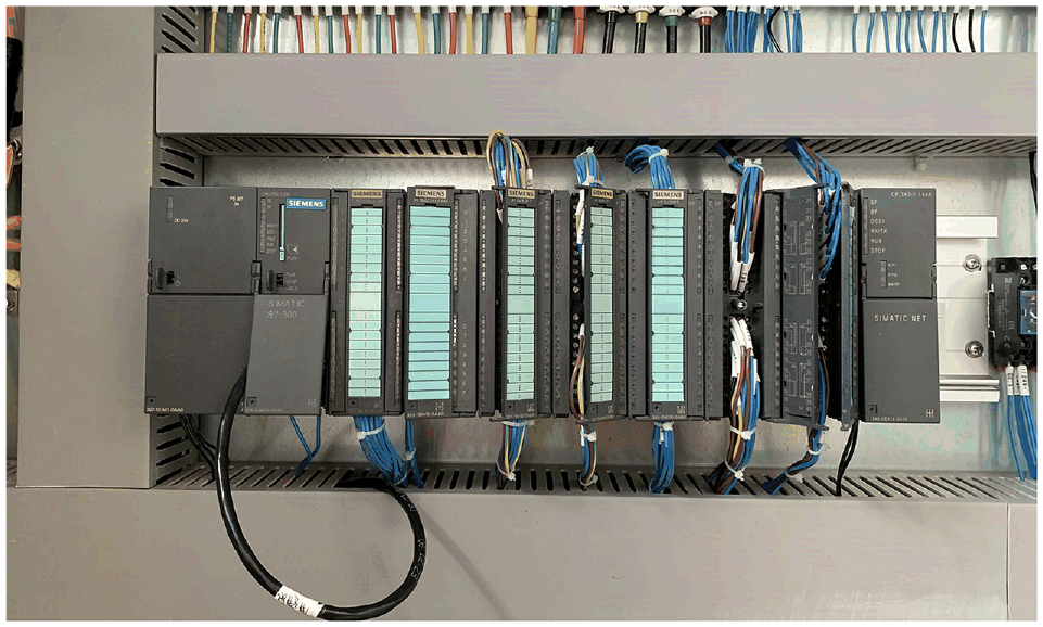
Rack fixed I/O module.
The platform uses the address supported by STEP7 software for programming, which effectively improves the continuity of the program. The PLC control system design of this experimental platform includes a field control system and a remote control system. 24 The field control is mainly the collection of signals, including temperature, flow, pressure, and other data, as well as the on-site operation of the equipment; and the remote control system is mainly used to achieve remote operation. The PLC program written by the software can realize functions such as data processing, logic judgment, and control execution, and the PLC program contains temperature, pressure and flow data acquisition and conversion program, equipment start-stop switch control program, inverter and power regulator control program, and system abnormal alarm and reset program.
The temperature, pressure and flow data acquisition and conversion program, of which temperature data acquisition and conversion program has 14 sections, the pressure data acquisition and conversion program has 4 sections, the flow data acquisition and conversion program has 5 sections, and the program sections of temperature T2, pressure P2, and flow GR2 are shown in Figure 7. By programming the FC function block, the AI/DI conversion module is written, that is, the collected signals of the temperature, pressure, and flow sensors are connected to the 1# analog module SM331 8AI × 16Bit. The analog module converts the collected current signals into digital signals that can be recognized by the CPU315-2DP main control module and stores them in the PLC data register DB201. The 2# analog module SM331 8AI × 16Bit sensor data collection process is the same as the 1# analog module.

Program sections of: (a) temperature T2, (b) pressure P2, and (c) flow GR2.
The equipment start-stop switch control program includes the program sections of diaphragm metering pump, circulating water pump, test water pump, front water pump, test electric heating, front electric heating, water tank heating, and electronic expansion valve, and the program section of the electronic expansion valve is shown in Figure 8.

Program section of the electronic expansion valve.
Inverter and power regulator control programs include diaphragm metering pump inverter, test pump inverter, front pump inverter, test electric heating regulator, front-end electric heating regulator, and water tank electric heating regulator. According to the real-time value of each data collection point or the requirements of actual operation, these programs can realize remote adjustment in the touch screen or configuration software.
System abnormal alarm and reset programs include monitoring over-temperature and low-flow of electric heating, over-temperature and low-flow of water tank heating, abnormality of various inverters, and over-current of circulating water pump, the program will promptly alert and prompt the specific cause of the abnormal state when an abnormality is found, while automatically suspending the operation of the device, waiting for the researchers to manually reset the alarm, confirm the alarm point and restart the device.
HMI measurement and control system design
A combination of appropriate automation and manual monitoring is more effective than expensive fully automated machines, 25 and human-computer interaction is to improve the interaction between researchers and devices by making the devices easier to accept the needs of researchers. 26 HMI is an interactive device that interacts between researchers and control systems. Researchers can use HMI to monitor the experiment rig and equipment operating status.
The single-tube heat transfer experiment measurement and control platform uses a WEINVIEW brand touch screen, the model is MT6103iP; the serial interfaces are Con.A: COM2 RS-485 2W / 4W, COM3 RS-485 2W, and Con.B: COM1 RS-232 4W / COM3 RS-232 2W; and built-in storage memory and perpetual calendar; built-in power isolation has good protection. The touch screen supports vector fonts for the Windows platform, supports three groups of serial ports to connect devices of different protocols at the same time, and the application is more flexible and convenient; it supports offline simulation and online simulation functions, which greatly facilitates program debugging.
WEINVIEW HMI configuration software EB Pro (EasyBuilder Pro) is used to design the interface. The design of the interface is critical to the convenience of the operation. It includes the understanding of the researcher and the experiment rig during the design, and the need to communicate the design intent to the researcher to facilitate operation and control. 27 Researchers need to collect temperature, pressure/differential pressure, and flow data on the experiment rig, at the same time control the equipment on the experimental table, and process and view alarms promptly. Therefore, six operation interfaces are included in the design of the touch screen interface as shown in Figure 9, including main page, temperature data acquisition operation interface, pressure/differential pressure data acquisition operation interface, flow data acquisition operation interface, control page operation interface and alarm history operation interface. In the design of temperature, pressure/differential pressure, and flow rate data collection operation interface, the left side can display the data changes in real-time, and the right side can store each updated data. When the PLC program is in the state of each collection point in the collection system, the format of its collected data is INT integer type. Correspondingly, in the EB Pro configuration software, the data format of the data is 32-bit Float, and the digital point setting of the data is consistent with the PLC, which can achieve the purpose of the complete display of the data collected by the touch screen.
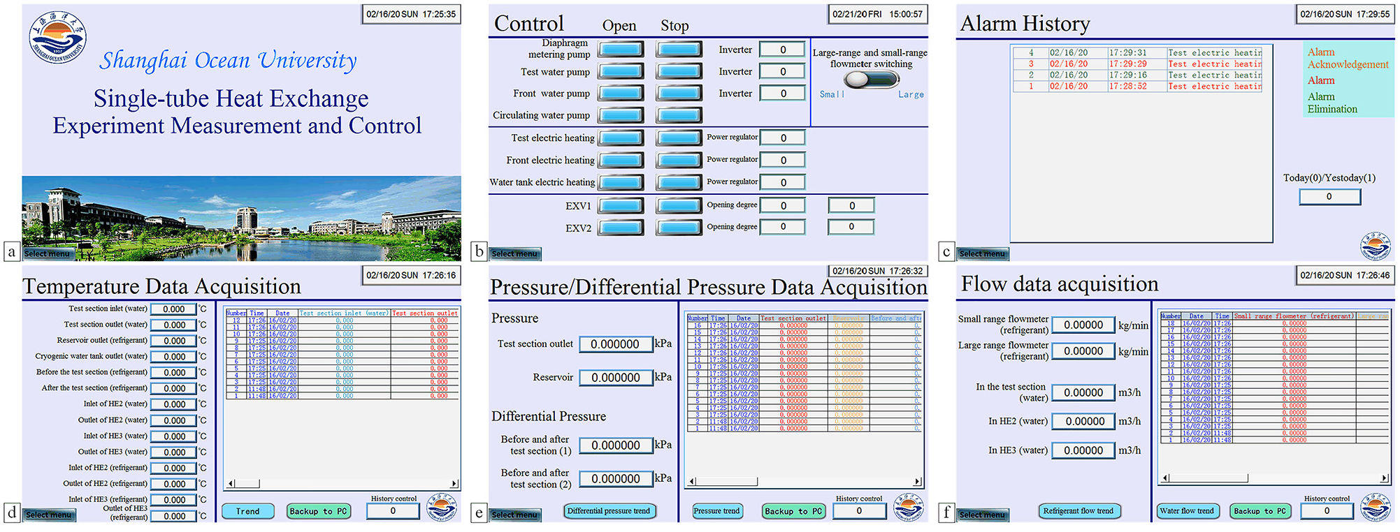
Operation interfaces of: (a) main page, (b) control page, (c) alarm history, (d) temperature data acquisition, (e) pressure/differential pressure data acquisition, and (f) flow data acquisition.
In the operation interface of the control page, a diaphragm metering pump, a test water pump, a front water pump, a circulating water pump, a test electric heating, a front electric heating, a tank electric heating, and an electronic expansion valve start simulation switch and stop simulation switch are designed. Besides, analog input boxes for frequency converters, power regulators, and openings are designed, as well as analog changeover switches for large-range and small-range flowmeters. In STEP7 software, the control program realizes the start, stop, and automatic control of electric heater, alarm reset, and water pump through I point and Q point. To realize the set analog keys in HMI can control the start and stop and alarm reset of the device, an intermediate variable M is added based on I point and Q point, corresponding to the address written in the EB Pro configuration software Set to M.
A pop-up window is designed inside each operation interface as shown in Figure 10, including a startup confirmation pop-up window, a selection menu pop-up window, a trend graph pop-up window, and an alarm bar pop-up window. The confirmation startup pop-up window can be set to reconfirm the startup of the device, to ensure the correct startup of the device and reduce the loss of the device. Researchers can use the pop-up window of the selection menu to switch the interface, which facilitates the operation steps. Also, in the pop-up window of the trend graph, the researchers can more intuitively observe the changes in the collected data over time, to make better statistics and analysis of the data. The pop-up window of the alarm bar can pop up immediately when an alarm is generated and prompt the abnormal situation of the specific equipment, which is convenient for the operator to solve in time. At the same time, to enhance the researcher’s experience when using HMI for human-computer interaction, during the design phase, the keys are set with security controls and key sounds, and the minimum key setting time in the security control allows the researchers to ensure that the keys are correct.

Operation interfaces of: (a) open confirmation, (b) select menu, (c) trend graph, and (d) alarm bar.
Communication and simulation debugging in single-tube heat transfer experimental measurement and control platform
Communication between PLC and HMI
The program written with STEP7 software needs to be downloaded to the PLC for debugging. The PC and PLC are connected for downloading through the traditional MPI port. In this process, the serial programming cable needs to be plugged and unplugged multiple times, which accelerates the wear of the serial programming cable and affects the communication effect. Therefore, install a wireless communication module and program it to have wireless communication capabilities. Furthermore, through the wireless function in the PC, the wireless module of the PLC, and the router device, the PC and the PLC are in the same local area network, and the Ethernet protocol is used for remote and fast communication and download.
After programming is completed in the EB Pro configuration software, there are two communication methods for downloading. One is to use the MPI line for downloading, and the other is to save the program to a USB flash drive and download the program to the touch screen through the USB flash drive, and the saved program name consists of letters, and the storage capacity of the USB flash drive is within 2G.
The controllers of the control system need real-time interaction, so real-time communication is particularly important. 14 First, the system parameter settings of HMI and PLC are consistent, and the system parameter settings of HMI and PLC are shown in Table 2. MT6103iP touch screen does not support Ethernet communication, so choose RS-485 to communicate with PLC. The pin wiring corresponding to the HMI is correctly connected, that is, the MT6103iP touch screen end uses 9-pin D-type female pin connection ports 6, 9, and 5 corresponding to the PLC terminal pin crimping pins connection ports 8, 3, 5.
HMI and PLC system parameter setting.

The single-tube heat transfer experiment rig is shown in Figure 11. The left side of the figure is the control cabinet, which contains PLC and touch screen. The communication between PLC and touch screen is carried out in this cabinet. The right side of the figure is the experimental equipment. After the power is turned on, researchers can see the data of the experimental platform on the touch screen and can operate the touch screen to control the equipment on the experimental platform.
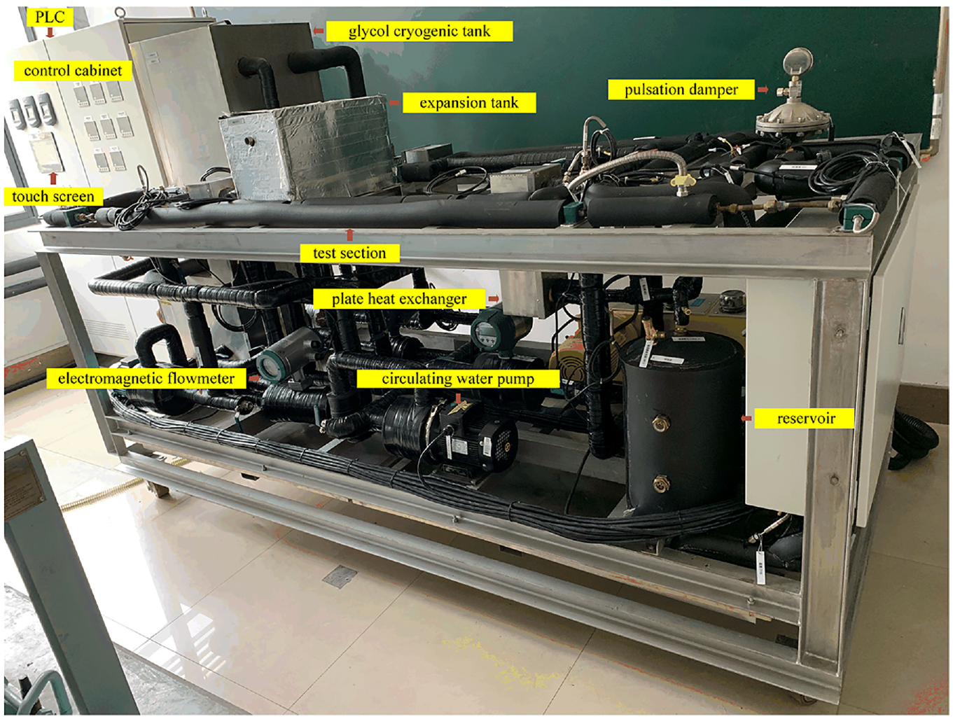
Single-tube heat transfer experiment rig.
Simulation and debugging of single-tube heat exchange experimental measurement and control platform
The simulation and debugging of the single-tube heat exchange experiment measurement and control platform includes two parts: data collection and equipment control. Data collection is to put data into the storage area for subsequent experimental analysis, 28 and it is the key to realize equipment control and automation. 29 After the experiment rig is powered on, the interface displayed in the HMI is the main page, and different operation interfaces can be entered by clicking the “select menu” analog switch. The data collection process is shown in Figure 12. The platform collects data through temperature sensors, pressure sensors, and flow sensors. Through the conversion of the PLC conversion program, the received current signal is converted into the actual temperature, pressure, and flow value displayed on the touch screen. In different acquisition interfaces, all experimental data will be displayed in real-time. The data acquisition adopts periodic sampling, and the sampling period is updated once every 5 s. The historical data is displayed in the historical data list and can be viewed through the analog slide switch. Furthermore, the researchers can type the number in the “history control” analog input box to specify the history file to be displayed. After opening the trend graph, click on the touch screen to select special points in the trend graph, whose time is displayed below the trend graph in seconds. Then, the researcher can click the simulation button “Image capture” to take a screenshot of the current operation interface, and the captured image can be saved using a U disk. If there are other special points to be saved, the user can click the trend graph on the touch screen again to select. The simulation button “Clear data” can clear the screen, and the simulation buttons “Pause sampling” and “Pause display” can be set according to the needs of researchers. After the data collection of the measurement and control platform is completed, by clicking the simulation button “Backup to PC”, the collected data are saved in the U disk, and then can be stored in the computer through the U disk.

Data collection process.
The equipment control in the simulation and debugging of the platform is to enter the operation interface of the “Control” by clicking the simulation switch “Select menu” in the touch screen. The user manually clicks on the analog switch in the touch screen to control the start and stop of each device and the switching between large and small range flowmeters and adjusts the frequency and power of the device and the opening degree of the electronic expansion valve. If an alarm is triggered during the operation of the experiment rig, an alarm bar will pop up immediately and prompt the cause of the alarm. The alarm can be canceled by clicking on the analog switch “Reset” in the pop-up alarm bar. The alarm that has occurred will be stored in the “Alarm History” interface.
After the power is turned on and the communication is successfully established, the researchers click on the start analog switch of the device on the control page of the HMI, and the sound of the connection of the intermediate relay in the electrical cabinet can be heard. The user checks the data display of the acquisition interface in sequence, adjusts the settings of each acquisition device in the control interface according to the display screen, and modifies the program through the STEP7 software and EB Pro configuration software. And finally, the complete display of the data can be obtained. The collected real-time and historical data of temperature, pressure differential pressure and flow rate, and the trend graph within a certain period are shown in Figure 13. By opening the trend graph, researchers can more intuitively observe the real-time dynamic change of data, and the change is based on the continuous update of the data displayed in the historical data list. Therefore, researchers can also observe the complete data link and changes of the data collected within a certain time by dragging the analog slide switch in the collection interface. In the figure, the curves of various data changes over time are smooth, and there is no up-and-down jumps and faults. It shows that the data acquisition is stable, and the connection between the measuring devices and the experiment rig pipelines is tight at each acquisition point, and the selected measuring devices are suitable for the experiment rig.

(a) Real-time and historical data of temperature, (b) trend graph of temperature, (c) real-time and historical data of pressure/differential pressure, (d) trend graph of pressure, (e) trend graph of differential pressure, (f) real-time and historical data of flow, (g) trend graph of refrigerant flow rate, and (h) trend graph of water flow rate.
During the experiment, because of the large space occupied by the experimental table and electrical cabinet, and the noise generated by equipment such as water pumps, researchers can choose remote control to experiment. Open the EB Pro configuration software and click “Online Simulation” to realize real-time monitoring and control of the experiment rig. By clicking “Image Capture” and “Backup to PC”, the data is directly saved in the folder set by the computer in JPG format and Excel form respectively.
Conclusions
In this paper, a single-tube transfer experimental measurement and control platform is designed, including the design of the PLC control system and the HMI measurement and control system, and the communication between the PLC and the HMI is established. The program segment written in the design of the PLC control system completes the data collection and conversion of each measurement point and the start-up of each device on the single-tube heat transfer experiment rig. In the design of the HMI measurement and control system, all the collected data are displayed on the touch screen, that is, the data is directly fed back to the researchers, and the equipment can be automatically controlled through the control interface. Through the simulation and debugging of HMI and PLC programs, the functions of the PLC program and the operation interface of the touch screen can meet the design requirements, ensuring the correctness of the control program and the reliability of the control system. At the same time, the application of the PLC program makes the touch operation screen of the equipment and devices of the experiment rig more convenient and concise, and the application of the touch screen improves the control efficiency of the measurement and control system of the experiment rig. The single-tube heat transfer experimental measurement and control platform realizes functions such as real-time data collection, historical data storage, real-time device control, real-time alarm and resets through PLC and HMI, and it reduces the difficulty for researchers to control the equipment and provides a reference for researchers in the design stage.
Footnotes
Handling Editor: James Baldwin
Author contributions
The work was realized in a collaboration of all authors. Wanying Chang designed, analyzed, and wrote this paper; supervision, Jinfeng Wang and Jing Xie; writing-review and editing, Wanying Chang; working with the STEP7 software, Wanying Chang, Mingtao Zheng, and Wenqiang Teng, working with the EasyBuilder Pro software, Wanying Chang and Yuyao Sun. All authors have read and agreed to the published version of the manuscript.
Declaration of conflicting interests
The author(s) declared no potential conflicts of interest with respect to the research, authorship, and/or publication of this article.
Funding
The author(s) disclosed receipt of the following financial support for the research, authorship, and/or publication of this article: This research was funded by National “13th Fiveyear” Key R&D Program of China (2019YFD0901604), the Key Project of Science and Technology Commission of Shanghai Municipality (19DZ1207503), and the Shanghai Science and Technology Commission Public Service Platform Construction Project (NO. 17DZ2293400).