
Abstract
In this article, eight enhanced single tubes and two smooth single tubes are selected for condensing and evaporating experiments with R134a. Heat transfer performance is compared under different test conditions. The heat transfer coefficients of small diameter enhanced tube are greater than those of large diameter tube in condensing test, while in evaporating test, the coefficients are approximately the same. The pressure drop of small diameter enhanced tube is greater than that of large diameter enhanced tube under same water flow velocity inside tube. Based on the experimental study result, a simulation model is proposed to evaluate small diameter tube replacement. The limit values of the theoretical simulation of STRPE (small tube replacement performance evaluation) are 1.257, 1.304, 1.286, 1.292 and 1.295 for tubes 1#, 2#, 3#, 4#, and 5#, respectively, for which replacement by a small diameter tube with the same enhanced fin configuration yields the same pressure drop and material consumption. According to the simulation model, the material reduction can be achieved directly for selected tubes. The study provides a reference for heat exchanger design in terms of cost reduction.
Introduction
Refrigeration and air-conditioning technology is widely used in commercial, residential and other industries. At present, the technology research and development meets the challenge of raw material price increase, energy savings and new energy efficiency standard improvements. In commercial refrigeration and air-conditioning equipment, especially in large chillers, the cost of the evaporator and the condenser is a large proportion of the total cost. Given this, the improvement in evaporator and condenser efficiency is very important. Shell and tube heat exchangers are widely used in chiller products, with liquid refrigerant filling the shell side. There are substantial researches into heat transfer enhancement for the falling film evaporator, the flooding evaporator and the shell-tube condenser. Fernández-Seara et al. 1 used an integrated fin tube to enhance the heat transfer performance in pool boiling with ammonia, with an average enhancement factor of 1.2 (maximum 1.3) compared to that of a plain tube. Li et al. 2 studied the dimpled enhanced heat transfer tubes for single-phase flow using simulation. The simulation results indicated that enhanced surface tubes could improve the heat transfer coefficient but lead to a high flow pressure drop. Performance evaluation criteria (PEC) have also been proposed to evaluate the performance of the heat transfer coefficient and the pressure drop. The results showed that different Reynolds numbers have different PEC values. Zhao et al. 3 investigated the falling film evaporation with R134a and R123 using four enhanced and smooth horizontal tubes. The reasons for the different performances of the enhanced tube with R123 and R134a involve the different film distributions for the two kinds of refrigerants. Hameed and Hussein 4 analysed one new type of enhancement on the inside and outside surfaces of the tube in a single-pass heat exchanger. The results showed that the heat transfer coefficient and the pressure drop across the heat exchanger increased with the enhanced surface tube. There exists a balance between the heat transfer coefficient and the pressure drop with different twisted ratio and Reynolds numbers. Gorgy and Eckels 5 conducted experiments on the convection boiling heat transfer performance of enhanced tubes with different pitch-to-diameter ratios. Taking the performance and the cost of refrigerant into consideration, an optimal P/d is determined. Kukulka et al. 6 experimentally studied the differences in condensing and evaporating heat transfer performance between the smooth outside and the enhanced heat transfer tubes. Under low mass flux, there is a small increase in the pressure drop and a decrease in the heat transfer coefficient when using the enhanced heat transfer tube in place of a smooth tube. This trend is different between smooth tubes and micro-fin tubes. Shah 7 summarized many empirical relationships for heat transfer during boiling on bundles of horizontal smooth and enhanced heat transfer tubes and proposed a desirable relationship. The above-mentioned studies focused on comparison of condensing and evaporating bundle heat transfer performance between enhanced and smooth tubes. All these research results are valuable to tube and shell heat exchanger design, while there is less information about small diameter tube replacement evaluation for the same enhanced fin configuration. Many studies8–13 are conducted on horizontal enhanced tube about the effect of heat flux, geometric enhanced fin, and mass flow velocity on heat transfer performance. The studies on single tube are of value to basic research for heat exchanger design. Enhanced heat transfer tube used in heat transfer can save energy and reduce emissions, but the investigation of cost reductions for the primary material used for heat exchanger production is insufficient. Higher heat transfer coefficient tubes can reduce the heat transfer area used in heat exchanger design. For heat exchanger value analysis and value engineering (VAVE), the replacement of existing tubes with small diameter tubes may lead to lower cost.
The evaluation of small tube replacement is studied in this article, which provides a reference for heat exchanger design. As R134a is widely used in large chiller products, it is chosen for experimental use. The heat transfer coefficient and pressure drop are experimentally studied between enhanced heat transfer tubes and smooth tubes for outside tube evaporation and condensation. A small tube replacement performance evaluation criteria (STRPE) is presented. Based on the STRPE, the results of using small diameter tubes to replace large diameter tubes are obtained. Finally, the 1# enhanced tube is selected for simulation to forecast the tendency of material reduction with different pressure drops.
Experimental apparatus and procedure
Test tube
The configuration of four types of enhanced test tubes is shown in Figure 1. The tube’s outer diameter Do, inner diameter Di, outer teeth height do, inner teeth height di and helical angle β are also shown in Figure 1. All these detailed parameters are shown in Table 1. Other parameters such as outer fin number No, inner fin number Ni, tube length L and weight W are also shown in Table 1.

Enhanced fin structures and photos.
Structural parameters of the test tubes.

Experimental apparatus
Figure 2 shows the schematic diagram of the experimental apparatus used to measure tube heat transfer coefficient and pressure drop during condensing and evaporating process. The experimental apparatus mainly consists of a refrigerant system, a water system and a data acquisition system. The refrigerant system consists of two barrels – one serving as the evaporator (installed at the bottom) and the other serving as the condenser (installed at the top). Both the barrels are equipped with three sight glasses to observe the evaporating and condensing state outside the test tube. Pressure transducer is installed on the barrel, which measures the refrigerant pressure. The water system consists of two independent water tanks, in which one provides cooling to the condenser and the other provides heating to the evaporator. Water flow metre, resistance temperature detector (RTD) and pressure differential transducer are installed on water pipe to measure water flow rate, entering/leaving water temperature and water side pressure drop, respectively.

Schematic diagram of experimental apparatus.
Experimental procedure
During the evaporating experiment, the test tube is installed in the evaporator and the auxiliary tube is installed in the condenser. The refrigerant evaporates in the evaporator and the vapour is condensed in the condenser. Due to a height difference between the evaporator and the condenser, the condensed refrigerant liquid flows to the evaporator and completes the evaporation cycle. Different saturated evaporating temperatures and heat fluxes can be obtained by adjusting the water flow rate and the water entering/leaving temperature of the condenser and evaporator. In the condensing experiment, the test tube is installed in the condenser and the auxiliary tube is installed in the evaporator. During the condensing experiment, the test sample is installed in the condenser and the auxiliary tube is installed in the evaporator, completing the condensing process.
Test data reduction, uncertainty and validation
Using the measured temperature, water flow rate and pressure drop, the heat transfer coefficient can be obtained. To assure the reliability of the measurement instruments, the heat balance should be within the range of ±4%. To simplify the calculation of experimental data, the heat loss of test apparatus is neglected and the water properties of pure water are taken. The calculations are as follows.
The heat transfer capacity in the test section is

The heat transfer capacity in the auxiliary part is

The heat balance is

The average heat transfer capacity is

The experiment simulated evaporation and condensation outside the tube. The refrigerant is under a two-phase flow state. The refrigerant saturated temperature is a function of the barrel pressure

The log-mean temperature difference is given by

The heat transfer coefficient is given by

The area of tube external surface is given by

The water flow pressure drop inside a single tube is also an important parameter. Water flows inside the tube and the Re number ranges from 10,000 to 100,000. The pressure drop can be expressed as
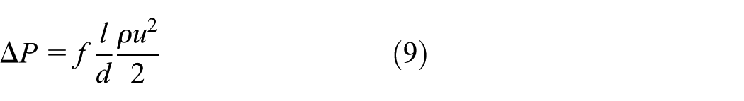
where f is the pressure drop friction factor. For a smooth tube, f can be calculated by Nikuradse’s 14 empirical equation when the Re is between 10,000 and 100,000

For a smooth tube,


The accuracy of all the parameters can be obtained directly or indirectly from the experimental data. The accuracy of the experimental data must be verified to determine whether they meet the requirement. The uncertainty of key parameters is calculated by referencing the literature. 16 The uncertainties of all the key parameters used in this article are listed in Table 2.
Uncertainty of key parameters.

To validate the reliability of the experimental apparatus, 25.40- and 19.05-mm diameter smooth tubes are selected for the evaporating test. To obtain the outside heat transfer coefficient, the saturated evaporating temperature is set at 5°C and the inside water flow velocity is set at 2.5 m/s. The heat flux varies from 5000 to 60,000 W/(m2·K). The heat transfer coefficient obtained by the test is compared to the theoretical simulation by equation (11).
To validate the pressure drop measurement reliability, another experiment is also performed. The experiment maintains consistency outside the tube heat flux of 40,000 W/ (m2·K) with a saturated temperature of 5°C. The inside water flow velocity varies from 1.0 to 3.0 m/s. The friction factor obtained by the test is compared to the theoretical simulation by equation (10).
According to Figure 3, the

Test apparatus validation: (a) evaporating test for ho and (b) evaporating test for f.
Heat transfer performance analysis
Different configurations of the enhanced tube may lead to different heat transfer performance. Heat transfer coefficient and pressure drop are two critical factors to evaluate the heat transfer performance. This section will present the experimental results of the heat transfer coefficient and pressure drop under different test conditions. This basic research will provide a foundation for subsequent research of small diameter tube replacement.
Heat transfer coefficient
Referencing to the chiller product operating conditions, the test conditions are given as follows.
In the condensing experiment, the water flow velocity inside tube varies from 1.0 to 3.0 m/s. First, the water entering temperature is fixed at 30°C and the saturated temperature is fixed at 40°C. Then, tests with the saturated temperatures of 35°C and 45°C are performed by adjusting the water entering temperature to keep the heat flux the same as the initial experiment (saturated temperature equals to 40°C). Five points are obtained for five water flow velocities from 1.0 to 3.0 m/s.
In the evaporating experiment, the water flow velocity inside tube varies from 1.0 to 3.0 m/s. First, the water entering temperature is fixed at 12°C and the saturated temperature is fixed at 5°C. Then, tests with the saturated temperatures of 10°C and 15°C are performed by adjusting the entering water temperature to keep the heat flux the same as the initial experiment (saturated temperature equals to 5°C). Five points are obtained for five water flow velocities from 1.0 to 3.0 m/s.
The purpose of these test conditions is to investigate the effect of saturated temperature on h under fixed heat flux. A great deal of data for h versus heat flux under different saturated temperatures can be obtained. Figures 4 and 5 show the test result of h with variable conditions for each tube. According to Figure 4, h increases with the increase in heat flux. For a fixed heat flux, h increases with the increase in saturated temperature. The maximum deviation percentage of the h values is approximately 10%, while the difference in h for the smooth tube is insignificant. Due to different configuration of the secondary enhanced teeth, the condensing liquid film on the tube 2# surface is easier to fall off, leading to higher heat transfer coefficient.

h at different saturated condensing temperatures: (a) 1A, (b) 1B, (c) 2A, (d) 2B, (e) 5A and (f) 5B.

h at different saturated evaporating temperatures: (a) 3A, (b) 3B, (c) 4A, (d) 4B, (e) 5A and (f) 5B.
According to Figure 5, h increases with the increase in heat flux. For different saturated temperatures, the increase in h is not obvious. The deviation of h at different saturated temperatures is within 5%. The h for evaporation is insensitive to saturated temperatures in these experiments for enhanced tubes. Due to different configuration of the secondary enhanced teeth, the evaporating bubble on the tube 4# surface is easier to break, leading to higher heat transfer coefficient.
Pressure drop
There is a positive correlation between the heat transfer coefficient and the pressure drop for the enhanced tubes. In this study, test tubes boil or condense refrigerant outside the tube and water flows inside the tube. The pressure drop is generated from the friction of the water flows inside the tubes. According to equation (10), pressure drop relates to Re number. Tests are performed with fixed saturated temperatures (condensation: 40°C and evaporation: 5°C) and heat flux (40,000 W/m2). Water flow velocity varies from 1.0 to 3.0 m/s corresponding to the Re numbers from 10,000 to 100,000, which indicates a turbulent flow pattern.
Figure 6 shows that the pressure drop increases with the increase in Re number. Each tube has a variable pressure drop gradient. The results show that the pressure drop of the small diameter tubes is greater than that of large tubes for the same enhanced fin configuration.

Pressure drop with Re: (a) 1A, 1B, 2A, 2B and (b) 3A, 3B, 4A, 4B.
Many researches are conducted for enhanced tubes based on experiment. Different tube configuration has a different heat transfer coefficient and pressure drop. Usually, the improvement in heat transfer coefficient leads to a larger pressure drop. Both factors should be taken into consideration during heat exchanger design for material reduction.
Small tube replacement
Enhancement performance evaluation
For the enhanced tube, a high heat transfer coefficient with low pressure drop is beneficial for an energy-saving design. It is difficult to balance the benefit of heat transfer coefficient and pressure drop. Many methods have been proposed by researchers17–26 to evaluate heat transfer performance, such as entropy analysis and the principle of synergistic effect.
The PEC,
In this article, an analogous way is proposed to evaluate two-sided enhanced tubes. The performance evaluation (PE) model is given by

The reason for proposing this model to evaluate the performance of the two-sided enhanced tubes is that h covers the two sides of the heat transfer coefficient. Refrigerant evaporation or condensation outside the tube is free convection. Inside the tube, water flow is the driving force for initiating heat transfer. Considering the energy consumption, equation (14) using heat transfer coefficient is more reasonable for the test tubes.
The experiment uses fixed saturated temperatures (condensation: 40°C and evaporation: 5°C) and fixed water entering temperatures (condensation: 30°C and evaporation: 12°C) along with different water flow velocities (from 1.0 to 3.0 m/s) to study the PE of the enhanced tubes.
Figure 7 shows that PE increases with the increase in water flow velocity for the condensing test, while the evaporating test has the opposite tendency. The other important result is that the PE of small diameter tubes with the same enhanced fin configuration is lower than that of large tubes for condensation, but the result is uncertain for evaporation. The PEs of small diameter tubes are greater than that of large tubes under lower water flow velocities, but they are lower under higher water flow velocities.

PE with water flow velocity: (a) 1A, 1B, 2A, 2B and (b) 3A, 3B, 4A, 4B.
Small tube replacement evaluation
The ultimate goal of this article is to evaluate the replacement of large diameter tubes with small diameter tubes. The replacement of tubes can contribute to a cost reduction for product design because small tubes use less material and result in a small size of heat exchanger. The first requirement for small tube replacement is to meet the requirement of heat transfer capacity performed by large tubes. The replacement evaluation is based on the single-tube experiment according to the heat transfer enhancement effect principle. 27
Replacement evaluation model
Replacement should be based on a fixed heat transfer capacity. The heat exchanger may have many tubes installed. This calculation model is based on the experimental data for single tube and extends to heat exchanger design.
The total heat transfer capacity is given by

The total water flow rate is given by

The total pressure drop is given by
The total heat transfer area is given by

The total heat flux is given by
The principle of the small tube replacement is given by


For simplicity, the
The material consumption reduction can be expressed as


According to the above calculation model, there are opportunities to reduce material cost. But the pressure drop may increase. Ratio of pressure drop can be expressed as

The following analysis is based on this calculation model and the experimental data for a single tube.
Replacement evaluation
The ultimate objective of small diameter tube replacement is cost reduction. Considering only the material consumption reduction,

To evaluate the small tube replacement, the STRPE is proposed, which is defined by
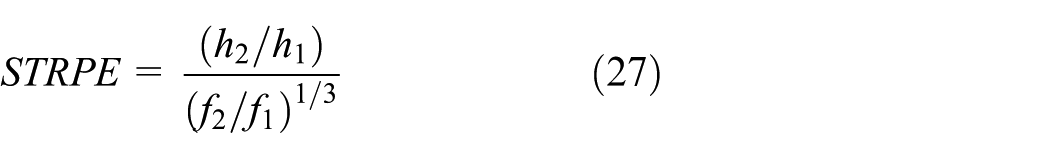


According to equations (25), (27) and (28), the limit value of STRPE can be obtained with no increase in pressure drop and material consumption for the enhanced tubes. The details are presented in Table 3.
Limit STRPE values.

Figure 8 shows the STRPE tendency versus water flow velocity in the experiment with fixed saturated temperatures and water entering temperature under different water flow velocities; higher water flow velocity results in larger heat flux. The tendency shows that the values of STRPE for 1# and 2# enhanced tubes in condensation decreases with the increase in water flow velocity. The 3# and 4# enhanced tubes in evaporation have the opposite tendency. However, the value of the smooth tube decreases with the increase in water flow velocity for both condensation and evaporation, which indicates that it is more valuable for condensation replacement with lower heat flux and evaporation replacement with higher heat flux. The absolute values of STRPE for tubes 1# and 2# are higher than for tubes 3# and 4#. The 1# enhanced tubes have the maximum value for replacement.

STRPE tendency versus water flow velocity.
Heat flux or water flow velocity can affect the value of the heat transfer coefficient. There are two methods for replacement with small tubes to achieve the same heat transfer capacity in heat exchanger design for reduced material consumption. Figure 9 shows the STRPE with different heat flux for the experiments performed with a fixed water velocity and fixed saturated temperature. The values of STRPE for enhanced tubes in condensation are greater than 1.0, and the tendency decreases with the increase in heat flux. However, the STRPE values for enhanced tubes in evaporation are less than 1.0 at a lower heat flux value of 50,000 W/m2, and the tendency increases with the increase in heat flux. It is verified that the results of evaporation with a larger heat flux may be more suitable for cost reduction. Figure 10 shows the STRPE with different water flow velocities for experiments under fixed heat flux and fixed saturated temperature. All STRPE values for enhanced tubes are greater than 1.0.
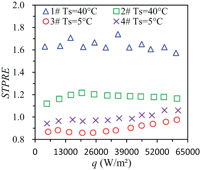
STRPE with different heat flux.

STRPE with different water flow velocity.
According to the STRPE calculation model, for the enhanced tubes with the value of
Similarly, if the heat flux is fixed, the STRPE values should be greater than 1.332, and it will lead to an equal pressure drop after replacement by enhanced tubes with the value of
The analysis of Figures 8–10 shows the result of small diameter replacement for a design that has achieved both cost reduction and lower pressure drop. Taking into account the calculation model and the experimental results, cost reduction is directly related to the values of
Forecasting
The 1# enhanced tube is selected for simulation to forecast the tendency of
Figure 11 shows the simulation results of the cost reduction tendency for the 1# enhanced tube. The data indicate that Sr increases with the increase in

Material reduction tendency.
In this section, an evaluation model for small diameter tube replacement is established and the tendency of STRPE values with variable test conditions is analysed. Different results are obtained from the experimental result for condensation and evaporation. A theoretical simulation is performed for the limit of STRPE to obtain the limiting value for cost reduction and reduced pressure drop.
The 1# enhanced tube is also selected as an example for forecasting simulation for Sr with varied requirements for
Conclusion
In this study, a small diameter tube replacement evaluation is performed based on the experimental results for a single tube. All the experiments and analysis are performed for eight enhanced tubes and two smooth tubes. The heat transfer performance analysis under different test conditions forms a baseline for the PE. Substantial work is carried out to evaluate single enhanced tubes in comparison with smooth tubes. The analysis provides a foundation to the small diameter tube replacement. The evaluation is mainly based on two assumptions. First, the material consumption is the only consideration for the cost reduction (the cost of changing tube manufacturing and system design–related costs are neglected). Second, the small diameter tube replacement evaluation only considers the same enhanced fin configuration with small diameter tubes. Based on these two assumptions, the following conclusions are drawn.
The heat transfer coefficient of enhanced tubes is different for condensation and evaporation under different test conditions. It is sensitive to the saturated temperature for condensation, while it is not sensitive for evaporation.
The PE values of the 1# and 2# enhanced tubes tested for condensation increase with the increase in water entering flow velocity, and the tendency of the 3# and 4# enhanced tubes for evaporation is opposite.
For the replacement with a small diameter tube (Ω = 0.75), the limit values of theoretically simulated STRPE are 1.257, 1.304, 1.286, 1.292 and 1.295 for tubes 1#, 2#, 3#, 4# and 5#, respectively, on the condition of same pressure drop and material consumption.
Under the same test conditions, only tube 1B has the potential for cost reduction when it replaces 1A. Moreover, a lower pressure drop can be achieved.
For a selected tube, a theoretically simulated prediction of Sr can be obtained directly by the STRPE simulation model. A large size heat exchanger with a great number of tubes has higher potential for a cost reduction design.
Footnotes
Appendix 1
Handling Editor: Oronzio Manca
Declaration of conflicting interests
The author(s) declared no potential conflicts of interest with respect to the research, authorship and/or publication of this article.
Funding
The author(s) disclosed receipt of the following financial support for the research, authorship and/or publication of this article: This project was supported by the Capacity Building Plan for some non-military university and colleges of Shanghai Scientific Committee (16060502600).