
Abstract
Reliable, smooth, and fault free speed control of a Permanent Magnet (PM) DC motor using an H-bridge is an important need for many industrial applications such as robotics, automotive, and process industry to improve the overall efficiency and productivity. The reliability of H-bridge depends on the semiconductor switches used. The faults in these components can lead to a complete failure of the system. This paper presents a dual redundancy-based fault-tolerant system with a Fault Detection and Isolation (FDI) unit that can detect, isolate, and replace the faulty switch with the standby to prevent the unwanted shut down of the system and support the process continuity thereby increasing reliability. MATLAB/Simulink environment was used for simulation experiments and the results demonstrate the stable operation of the motor in the events of faults while maintaining its speed. The presented work establishes that the dual redundancy-based fault-tolerant H-bridge with the FDI unit is a highly reliable solution for the speed control of a DC motor.
Introduction
Fault-tolerant control
Fault-Tolerant Control (FTC) strategies are utilized to improve the reliability of the machines by preventing events failure due to faults. A fault is commonly known as a deviation in the output of a system from its desired output while failure is known as a complete shutdown of a system. The main role of an FTC is to prevent faults in critical systems that can result in its failure. The systems used for critical missions such as unmanned aerial vehicles, aircraft, and nuclear facilities cannot tolerate failure, hence, to improve the safety and reliability of such systems FTC is used. Redundancy is one of the methods used to design an FTC system and it falls into two main categories: analytical redundancy and hardware redundancy. Analytical redundancy is further categorized into active and passive. The active analytical redundancy consists of fault detection, its isolation, and reconfiguration of a controller but that makes it a complex, high computational and slow in performance, however, it has the advantage of incorporating a wide range of faults. The passive analytical redundancy is a relatively simple and faster method as it is based on a robust controller design that can deal with the only considered uncertainties and faults in a system, thus, it cannot accommodate a wide range of faults. 1
Active Fault-Tolerant Control System
The main component of an Active Fault-Tolerant Control System (AFTCS) is the Fault Detection and Isolation (FDI) unit whose responsibility relies on the detection of faults occurring in actuators and sensors as shown in Figure 1. The FDI unit is implemented by designing an observer model that generates the estimated values which are used in case a component incurs fault. After detecting and isolating a fault, controller reconfiguration is performed by the FDI by utilizing the estimated parameter values by the observer to adopt new conditions. AFTCS has the advantage of including a wide range of faults and it’s an online fault detection-based method but that makes it a complex, high computational, and slow in performance. 1
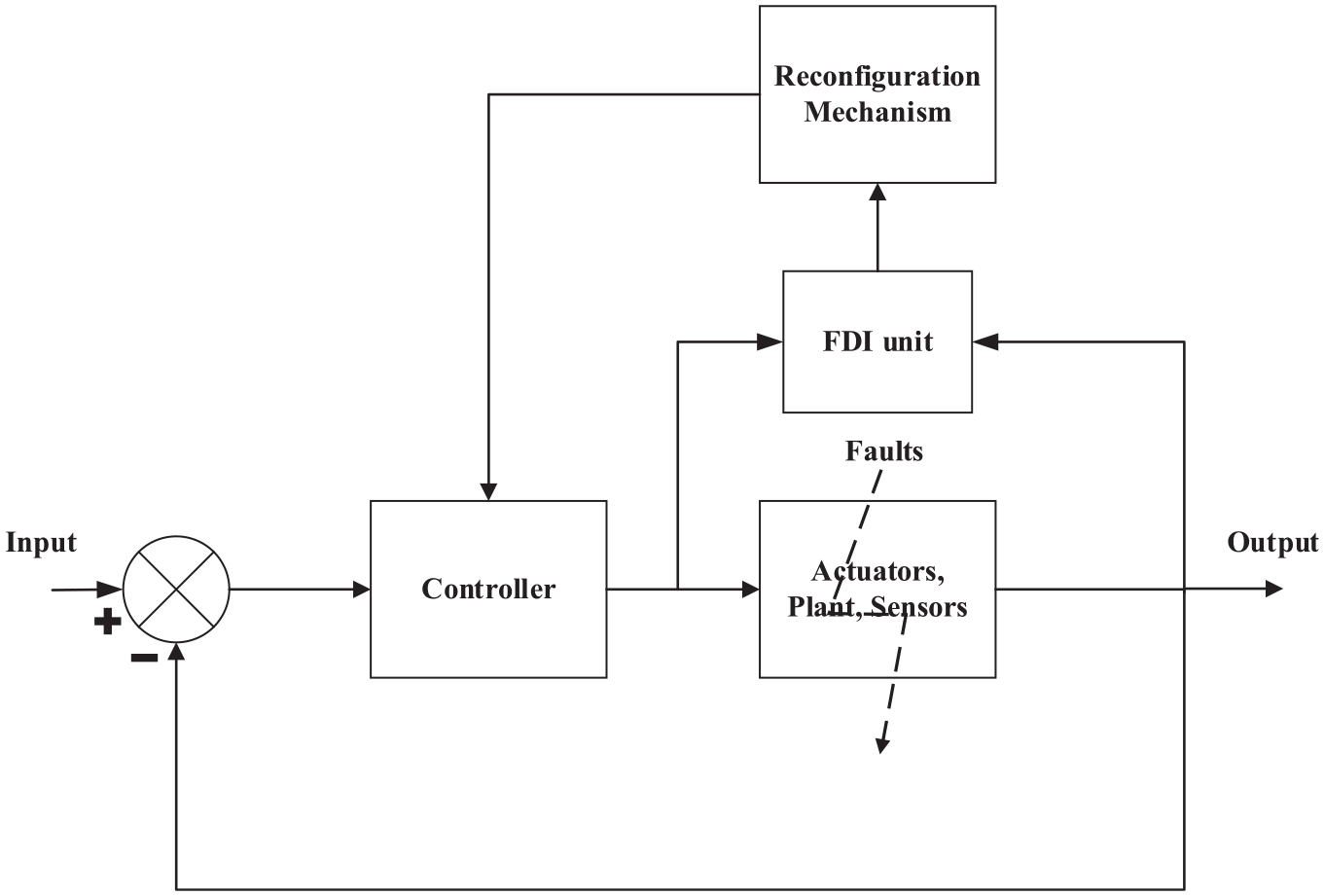
AFTCS architecture. 1
Passive Fault-Tolerant Control System
The Passive Fault-Tolerant Control System (PFTCS) is much simpler than the AFTCS as shown in Figure 2. It does not require an FDI unit and during the design stage, all possible faults are assumed. Since the controller design of PFTCS is offline based and has a static structure, therefore, its functionality structure remains the same after faults. The main advantage of PFTCS is the fastest response capability because of the simpler structure. As the PFTCS controller is designed for only considered uncertainties and faults, therefore, accommodation of complex faults risks its functionality. 1

PFTCS architecture. 1
Hardware redundancy
In the hardware redundancy, along with the main component another secondary component is installed that can perform the same functionality, making it one of the most reliable ways of increasing the reliability of the system. Whenever the main component fails in such an FTC system, the secondary component overtakes to perform the same functionality, thus avoiding the damage and failure of the system. 2 The basic dual redundancy system is shown in Figure 3. The reliability of the overall system increases as the system will only fail if both components fail to perform otherwise the system will keep on performing its normal operation.

Dual redundant system. 1
Speed control of DC motor
Pulse Width Modulation (PWM) is a popular technique used to control the speed of a DC motor by controlling the duty cycle of the driving voltage of the switches. The speed of the motor can be easily controlled by varying the duty cycle of the PWM signal and is directly proportional to the duty cycle that is greater the duty cycle, the greater will be the speed of the motor. Figure 4 shows the waveforms of 0%, 20%, 50%, 80%, and 100% duty cycle signal applied to the switches to control the speed. 3
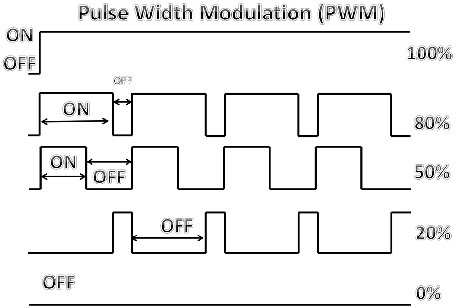
PWM waveforms at different duty cycles.
The H-bridges are commonly used for speed control of DC motors in both forward and reverse directions. The construction of H-bridges is mainly based on the power semiconductor. The reliability of the switches is of great importance as these switches in some cases can turn out to be faulty for example; if a switch burns out due to the passage of higher current that can lead to a catastrophic failure of the complete system. Therefore, to prevent catastrophic failure of the system, fault-tolerant strategies are gaining popularity and are being utilized in a wide range of applications including power converters. 4
The H-bridge power converter circuit topology is shown in Figure 5. The power switches mainly use the insulated gate bipolar transistors (IGBTs) in H-bridge for power switching. The pair of four IGBTs could be utilized for controlling the speed of a DC motor by varying the input signal of the switches. The mathematical representation is given as: 3

Where Ton is the time as soon as the signal is in high (on) state and Toff is the time as soon as the signal is in the low (off) state.

DC motor speed control using H-Bridge.
Output current having a resonant load of power converters is described as

Where
When a PWM signal is applied to SW1 and logic high to SW4, then the IGBTs would make a full path from Vs to the GND and this makes the motor rotate in the forward direction. By changing the duty cycle of PWM applied to SW1, the speed of the motor can be varied. Likewise, when the PWM signal is applied to SW3 and logic high to SW2, then the IGBTs would make a full path from Vs to the GND and this makes the motor rotate in the reverse direction. By using the PWM signal, we are essentially switching the motor on and off at a certain rate to control the speed.
Literature review
Hossein Iman in his work 6 explained how to bypass, protect, and diagnose the fault that appears on an H-bridge if they are placed in cascade. The author proposed a redundancy strategy to make the system fault-tolerant. The major problem in cascade systems is that as the number of power switches increases, it increases the reliability issues in cascaded H-bridge converters. The proposed strategy showed the system detected the faulty switches, bypassed the faulty switches, and reorganized the cascaded H-bridge converter to improve the overall performance. In paper, 7 the author proposed an isolation and elimination technique to make the system fault-tolerant. The proposed strategy uses several relays to perform isolation with which the overall system performs normally even during a fault however, the overall output voltage level decreases with the introduction of a fault.
In Ref. 8 author analyzes the fault-tolerant dual multiphase motor control system. The series-connected phenomena were proposed by the author and a standard H-bridge topology. The work reported in Ref. 9 presented cascaded H-bridge inverter for large scale motor driving. The fault-tolerant control is proposed for equalization of power that means when the imbalance is introduced in power modules, they can operate normally even in case of failure. In Ref. 10 authors compare the series and H-bridge methods for fault-tolerant of motor drives. The aerospace applications use H-bridge because it lowers the weight and cost of the system.
The work by Jaladi Suresh and Shaik Shareef 11 focuses to improve the fault-tolerant control performance of the cascaded H-bridge inverter by lowering the CM voltage. For this purpose, first, the algorithm is built to find the best fault with maximum voltage and then the modified technique is presented to calculate the voltages under faults. The effectiveness of the work compares with the old ones in different scenarios. In Ref. 12 the authors proposed a dual-channel switched reluctance motor. This technique is composed of two models. The first model operates like 3-phase SRM is abounding by H-bridge inverters. The second model is composed of coupled SRMs that are providing current. Both used to eliminate the faults and realize the fault-tolerant operations. The simulation results show the advantages of SRM and couples SRMs. In paper 11 the fault-tolerant control based on space vector Pulse Width Modulation (PWM) is presented by maintaining the magnetomotive force of motor rotating and fixed and fault-tolerant based on the current hysteresis band pulse width modulation is to keep the torque same before and after the fault. Both strategies are verified by the experiment.
The paper 12 presented a fuzzy logic control for the effective performance of induction motor drive. The fuzzy logic consists of two inputs speed error and deviation of speed error. The comparison of PI and Fuzzy is presented in this paper and the simulation results are used to observe the behavior of both. The study 13 proposed consistent fault to diagnosis and fault-tolerant control strategy of sensor faults in the cascaded H-bridge rectifier. The presented work can achieve the exact position of the faulty sensor in less time. The studies14,15 show the dual hardware redundancy for engine sensors application in which the primary component performs all the normal operations until it fails and then back-up components come into operation to perform the tasks. With this approach, a single point of failure can be eliminated due to a single sensor or actuator and the overall failure of the system can be avoided that would have been caused by a single component.
The previous work addresses the H-bridge for controlling the motor’s speed, but the elimination of faults and maintaining them was not quiet introduced because of the complexity of the method. Fault-tolerance is an important area of research in the current period because one can overcome the huge damage. If there is a model present, which makes the system work even in case of faults can save from a disaster. While there has been a lot of research conducted in the fault tolerance domain, however, no work has been done related to fault tolerance in H-bridge DC motor speed control up to over best knowledge.
A fault-tolerant strategy is required that can identify and protect the power switches from becoming faulty and saving the complete system shutdown. The presented fault protection strategy of our system will be able to diagnose the fault by detecting the faulty switches. The faulty switches will be detected by the presented solution and will be able to eliminate the effect of the particular switch with the help of the bypassing technique. The secondary component will take over to avoid the severe damage and it will allow the normal operation to continue.
The existing model does not have the feature to avoid faults on its own therefore fault-tolerant strategies can be utilized to convert the existing model to a more robust and reliable one. In this paper, our contribution is to add the dual hardware redundancy-based fault-tolerant control system that will be able to rectify the overall failure problem of the system when a pair or multiple switches fail during the operation. The approach used will be able to detect the faulty switches, provide an alternative path in case of failure of the switch by bypassing the faulty switches, and ensure the protection of the power switches.
The presented fault protection strategy of our system has not been implemented before in H-bridge for the speed control of the DC motor from the best of our knowledge. The solution presented will be able to diagnose the complete fault by detecting the defective switches and eliminating its effect to improve the overall performance.
Further contents of the paper are organized as follows. Section 2 presents the methodology of the system. Section 3 contains the important results and discussion of the paper’s findings. In the end, section 4 contains the concluding remarks and possible future directions.
Research methodology
The fault-tolerant H-bridge for controlling the speed of a DC motor is implemented in the MATLAB and Simulink platform. The IGBT based H-bridge model available in the MATLAB and Simulink environment is utilized as a base model for the speed control of DC motor. For the implementation of fault tolerance, a dual hardware redundancy approach is proposed and integrated with the MATLAB provided model. 16
In the H-bridge model, four IGBTs are utilized as a switch because of their good properties in power switching applications. During the operation of H-bridge, two transistors are operated at a time by firing a voltage pulse on the gate that results in a positive voltage and rotation of the motor in one direction while when the remaining two transistors are operated a negative voltage appears on the motor causing it to rotate in another direction. The pair of two freewheeling diodes are operated during the operation to bypass the two counter-transistors from the opposite polarity. 17
When an IGBT is operated a forward voltage VF drop is developed across the collector-emitter VCE junction typically of 1 V in the range. A similar property is available in the MATLAB and Simulink model. For the simulation, the block available in this model does not require the gate current control signal, however, it utilizes Simulink signal (1/0). The model for the DC motor has the predefined specifications (24V 5HP 1750 rpm) and a load similar to a fan is utilized by the Simulink model. When the duty cycle is changed from 0 to 100% the mean armature voltages are varied between 0 to 240 V.
The fault-tolerant approach to the H-bridge is dual hardware redundancy that will increase the reliability of the system. In dual hardware redundancy, there is a primary and backup hardware component. The primary part performs all the normal operations until it fails and backs up components that take the charge to perform the normal tasks. With this approach, a single point of failure is eliminated, in which the overall failure of the system can be avoided that would have been caused by a single component. In fault-tolerant H-bridge, eight transistors will be utilized in which four transistors will be acting as primary while the remaining four transistors will be used as backup hardware components. During the normal operation, the primary four transistors will be working two transistors at a time to control the speed of a DC motor. However, if any, of the primary switches face a fault the redundant hardware will take over to continue the normal operation to provide the output to control the speed of a DC motor.
The flowchart of the fault-tolerant system is shown in Figure 6. The system is initialized with assumed parameters before simulation. The H-bridge consists of four transistors that work in a pair of two groups. First transistors 1 & 4 will be operated simultaneously that will provide a positive voltage to the DC motor causing it to rotate in a clockwise direction afterward transistors 2 & 3 will be operated simultaneously that will provide a negative voltage to the DC motor causing it to rotate in a counter-clockwise direction. During the operation, the transistors will be checked to see if anyone of them is faulty. If so, the backup transistors will be utilized instead of the primary transistors to provide the voltages to the DC motor.
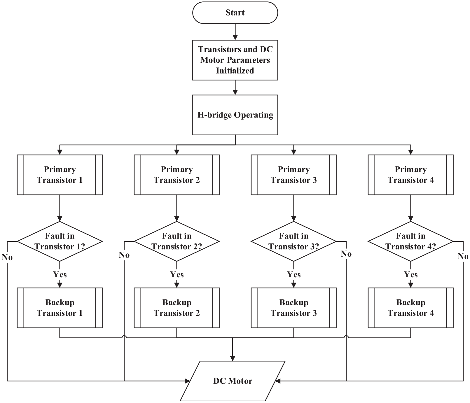
Flowchart of dual redundant fault-tolerant H-bridge.
The block diagram of the overall system is shown in Figure 7. The supply voltages are provided to both the H-bridge section and backup components. The primary section H-bridge is working in a normal condition. The Fault Detection and Isolation (FDI) block make sure that the DC motor receives the right voltages. If during the normal operation a fault is detected, the fault detector and isolator block will eliminate the faulty transistor by the backup transistor to ensure the normal operation of the load.

Block diagram of dual redundant fault-tolerant H-bridge.
The assumptions of the work include zero time in the switching action of H-bridge IGBTs. The limitations of the work include the increase in the physical size, weight, complexity, and cost of the overall system due to hardware redundancy. The proposed solution will fail if both redundant switches simultaneously fail and will cause the overall shutdown of the system. Moreover, ideal switches are considered in which they have zero resistance in the closed state and infinite resistance in the open state. However, these posses a small resistance in the closed state and high finite resistance in the open state.
Results and discussion
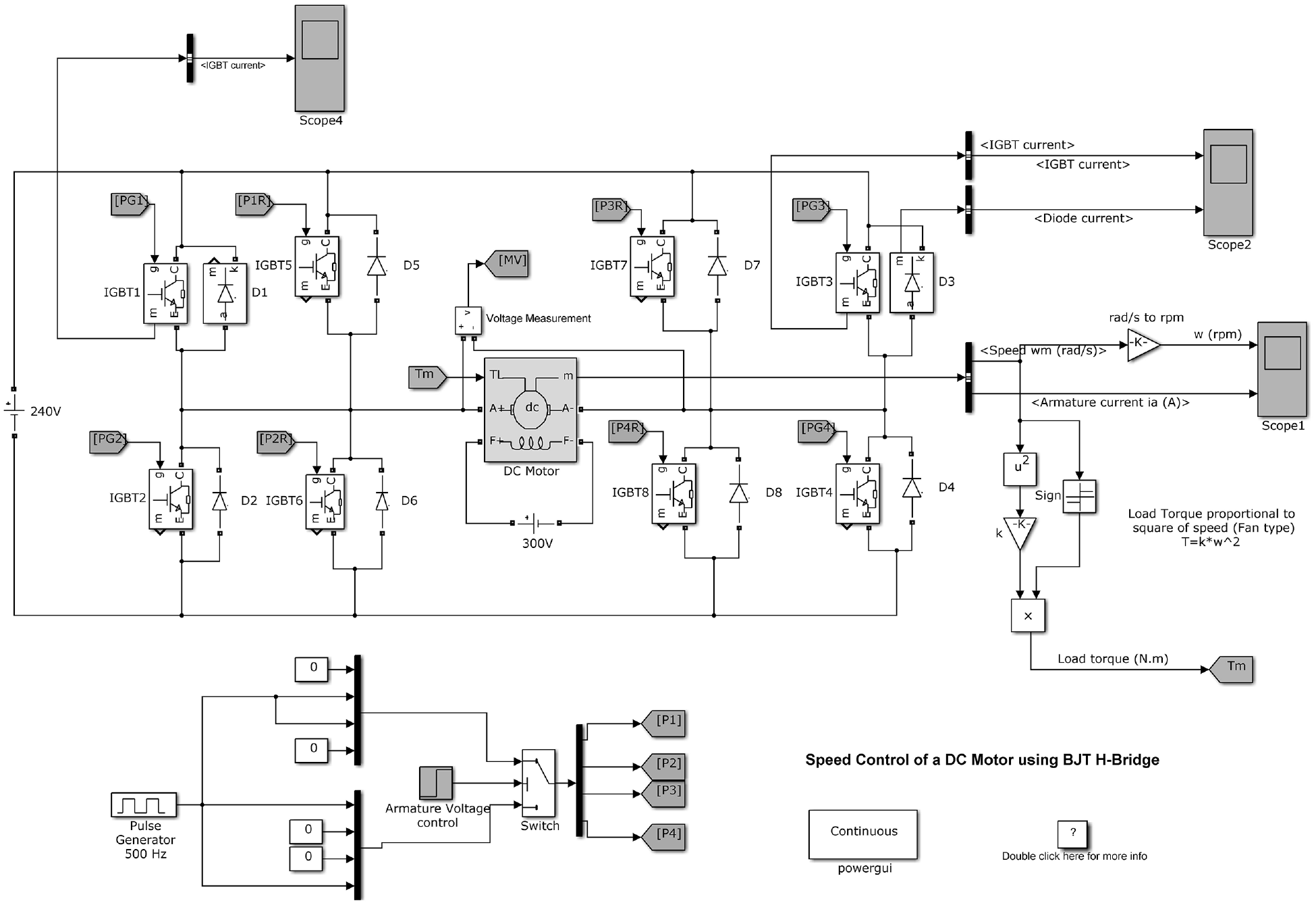
To control the rpm of the DC motor, the power electronic system in MATLAB and Simulink environment is implemented by utilizing the available model provided in Figure 8. Further changes are introduced in this model to achieve the desired outcome. To understand this model, it is divided into four parts.

Speed control of a DC motor using H-bridge model implemented in MATLAB.
H-bridge switches
Four IGBT switches with freewheeling diodes are utilized in the construction of this model. The IGBTs have a forward voltage drop VF of 1 volt while diodes have a forward voltage of 0.8 volts. During the operation, two pairs of IGBTs are switched simultaneously by the control circuitry having the sequence as follows Q1 & Q4 or Q2 & Q3. To supply the positive voltages to the DC motor to rotate it in the forward direction, Q1 and Q4 are supplied with the firing angles, and D2 & D3 work as a freewheeling diode during the operation. Moreover, to supply the negative supply voltages to the DC motor to rotate it in the reverse direction, Q2 and Q3 are supplied with the firing angles, and D1 & D4 act as a freewheeling diode.
Control circuitry for switches
The IGBTs require a control gate signal to operate therefore the gate is operated by providing a Simulink signal (1/0). The gate is turned on when 1 is applied while it is off when 0 is applied. The variation in the duty cycle results in variation in the rpm of the DC motor.
Permanent magnet DC motor
The DC motor used in the model is a preset model of permanent magnet DC motor having 5 HP 240 V 1750 rpm as given in Table 1. The motor simulates the fan equivalent load type in which the square of the speed is proportional to the load torque. Moreover, the mean armature voltages can be supplied from 0 to 240 V while the duty cycle is changed from 0 to 100%. All of these settings are initialized in the pulse generator block in the Simulink model.
Rated motor parameters.

Measurement units
Two scopes are utilized for measurement purposes. Scope 1 provides the information of the motor’s rpm, armature current, and load torque while scope 2 provides the information of IGBT and diode current.
The model is simulated by setting the duty cycle to 100% that provides 240 V to the motor and rotates it in a positive direction at max rpm of 1750 as shown in Figures 9 and 10. Initially, the motor draws a high inrush current when the motor is trying to attain the maximum speed but after some time its current starts to decrease until it becomes constant because now the speed of the motor also becomes constant.

Motor voltages at 100% duty cycle.

Motor speed and armature current at 100% duty cycle.
To operate the motor in reverse direction armature voltage control module can be utilized in which by varying the step size of the signal the direction can be altered that is if step time is set to 0.5 s, as the time reaches 0.5 s the voltages at armature suddenly reversed to vary the direction of dc motor in an opposite side that switches the rpm from +1750 to −1750. Similarly, the voltages across the motor also change its polarity from +240 V to −240 V.
During the operation, the current and voltage will be passing through IGBTs illustrates the phenomenon as presented in Figures 11 and 12.

IGBT 1 voltage at 100% duty cycle.

IGBT 1 current at 100% duty cycle.
The existing model does not have the feature to avoid faults on its own, therefore, fault-tolerant strategies can be utilized to convert the existing model to a more robust and reliable one. Our contribution in this model will be to add the hardware redundancy-based fault-tolerant system that will be able to rectify the overall failure issue of the system when a single switch fails during the operation.
The proposed redundant, fault-tolerant system is implemented on the H-bridge for reliable speed control of a DC motor in Simulink is shown in Figure 13. The FDI is implemented in this model for fault detection and isolation shown in Figure 14. FDI consists of four different inputs for each IGBT and produces two outputs for each pair of IGBT and redundant IGBT in the H-bridge circuit.
Proposed dual redundant fault-tolerant H-bridge system.

Fault detection and isolation unit.
In a normal scenario, when gate signals are applied to each IGBT, they perform switching properly. However, when an IGBT becomes faulty the behavior of the system completely deviates from its normal operation.
In the presented model, the Fault Injection Unit (FDI) is implemented to inject faults in any switch. The fault in a switch is represented by fail (0) while normal (1) shows a healthy switch, as shown in Figure 15. Inside the FDI unit, there are four-fault detector blocks whose function is to detect the fault in each IGBT switch. Moreover, an average voltage function for calculating the average voltages across the motor is implemented as shown in Figure 16.

Dashboard of fault injection unit.

Internal architecture of FDI unit.
When a fault is injected in a switch, the FDI unit by using the fault detector signal detects the unusual behavior of the switch and immediately isolates the faulty switch by turning off its gate signal. At the same moment, the redundant IGBT switch is providing the gate signal to overtake the working of the faulty switch and maintain the overall functionality of the system.
The fault detector unit inside the FDI unit consists of two signals, first is the constant zero signal block that is representing that the redundant IGBT is turned off while the primary IGBT is working correctly. Second is the healthy signal that is used to turn on the primary IGBT as shown in Figure 17. As the fault is injected the fault control signal actuates the switch and isolates the faulty switch by providing no gate signal to it while at the same moment it applies the gate signal to redundant IGBT.

Fault detector.
The duty cycle is set to 100% and a fault is injected by operating the manual switch as shown in Figure 18. The voltages across the motor drop, but within a few milliseconds the redundant IGBT takes over to prevent the failure of the system.
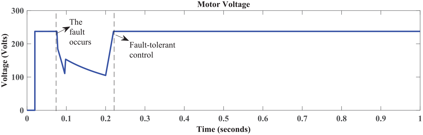
Motor voltage during fault.
Similarly, the motor running at maximum rpm of 1750 deviates from its set point, but after a delay, it regains its speed as shown in Figure 19. The high inrush armature current of the motor also drops to zero during the fault period but regains it when the redundant IGBT takes over the functionality of the primary IGBT.

Motor speed and armature current during fault.
The variations in voltage due to the fault across the IGBT 1 redundant assembly are expressed in Figure 20. The voltage of both redundant switches will be the same, therefore, are shown in a single graph. The FDI unit will be isolated the defect IGBT and replace it with the redundant IGBT by supplying it with the gate signal.

Redundant IGBT 1 assembly voltage during fault.
The current passing through the primary IGBT becomes zero as the fault occurs as shown in Figure 21. The FDI unit isolates the faulty IGBT and replaces it with the redundant IGBT by supplying it with the gate signal as shown in Figure 22.

Primary IGBT 1 current during fault.
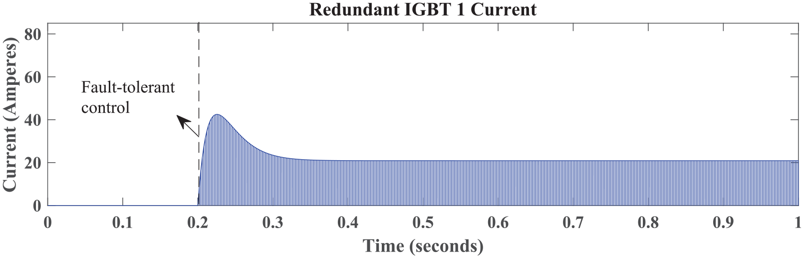
Redundant IGBT 1 current during fault.
The overall changes in the behavior of the current of redundant IGBT 1 assembly during fault are shown in Figure 23. In the normal operation, the motor draws a high inrush current but equally the fault is injected the current falls to zero, however, after a small delay the FDI unit successfully detects the erroneous switch, isolates, and replaces it with redundant IGBT and the system resumes its normal performance.

Redundant IGBT 1 assembly current during fault.
It can be seen from the simulation results that the proposed model with dual redundancy for actuators is robust to faults and it can maintain the functionality of the system and avoid the single point of failure if any or all primary switches fail during the operation, therefore, the presented fault-tolerant strategy is the best solution for reliable speed control of DC motor. Moreover, such work is novel and not found in the literature so far, therefore, we were not able to compare our results with existing works.
Conclusions
This paper presented a dual redundancy-based fault-tolerant system using MATLAB/Simulink environment that can detect, isolate, and substitute the faulty semiconductor switch to maintain the performance of the permanent magnet DC motor. The FDI unit was implemented to detect the fault during the operation and remove it to prevent the single point failure. The simulation results showed that during a faulty condition the motor voltage, rpm, armature current, and IGBT current deviate from their normal operation, but as the redundant component takes over the parameters become stable to prevent the failure of the overall system. The study showed that the dual redundancy-based fault-tolerant H-bridge is a very reliable solution for the speed control of a DC motor as it has given the ability to prevent the failure of the system.
Future work may include implementation of Triple Modular redundancy (TMR) in H-bridge switches, passive, and active fault-tolerant techniques with reliability analysis. The TMR will further increase the reliability of the system than dual redundancy but the cost of the system will increase. However, in mission-critical applications, where reliability is more important than cost, TMR can be implemented instead of dual redundancy.
Footnotes
Acknowledgements
The authors would like to thank to colleagues for suggestions to improve the paper quality.
Handling Editor: James Baldwin
Declaration of conflicting interests
The author(s) declared no potential conflicts of interest with respect to the research, authorship, and/or publication of this article.
Funding
The author(s) received no financial support for the research, authorship, and/or publication of this article.