
Abstract
The risk of danger in industries is increasing due to the unexpected shutdowns owing to the unwanted faults in the components. These faults can also lead to a complete failure of the system causing costly production losses and safety issues. Therefore, Fault-Tolerant Control (FTC) techniques are used for such systems to get better reliability, and safety to prevent faults. This paper presents a Modified Triple Modular Redundancy (MTMR) based fault-tolerant system for a separately excited Direct Current (DC) motor with a Fault Detection and Isolation (FDI) unit that can detect, isolate, and replace the faulty switch with the standby switches to prevent the unwanted shut down of the system and support the process continuity thereby increasing reliability. The proposed MTMR will still be able to provide output with only one healthy switch with the other two in the faulty conditions. MATLAB/Simulink software was used for the experimentation process to check the performance of the system. The presented work establishes that the MTMR-based fault-tolerant H-bridge with the FDI unit is a highly reliable solution for the speed control of a separately excited DC motor. The comparison of the proposed work with existing works also demonstrates its superior performance.
Keywords
Introduction
Fault-tolerant control systems
To overcome and control the unwanted shutdown whenever a fault occurs, fault-tolerant control (FTC) techniques are utilized. A fault is caused due to the excess flow of current or interruption in the circuit or due to a faulty switch that may lead to a sudden breakdown of the system. Such faults can never be tolerated for safety and production-critical systems. Therefore, FTC techniques are used for such systems to get better reliability, and safety to prevent unwanted shutdown and power/production losses.
Redundancy techniques
One of the strategies used to construct an FTC system is redundancy, which is divided into two main types: analytical redundancy and hardware redundancy. Analytical redundancy is further classified into two types: active and passive.1,2 A separate unit called Fault Detection and Isolation (FDI) is utilized in the active FTCS (AFTCS) to identify and isolate the defective components. After the fault has been isolated, the controller is reconfigured to adapt to the new conditions. The AFTCS, on the other hand, has a complicated structure and runs slowly due to excessive computations. No FDI is employed in the passive FTCS (PFTCS), instead, defects are evaluated at the design stage. The PFTCS has a faster response time than the AFTCS, but its functioning is limited to the faults established during the design stage. For hardware redundancy techniques, there are two popular types: Dual Redundancy (DR) and Triple Modular Redundancy (TMR). In the DR architecture, the main component along with another secondary component is installed to carry out the same function as shown in Figure 1. Whenever the main component fails, the system is taken over by the secondary component maintaining operational continuity. 3
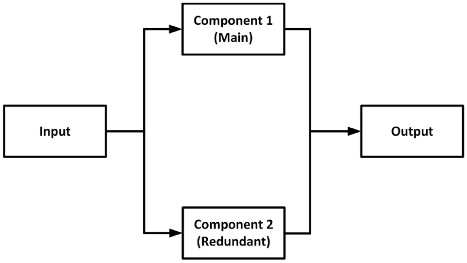
Dual redundant (DR) system. 1
To determine the reliability RDR of a DR system, let us suppose two components with reliability R1 and R2 are working in parallel such that the system will work when both or any one of the components work, that is


Let R1 = R2 = R


The other technique is the TMR in which three modules/channels are running at the same time and a voter performs voting to determine the final output. If one of the channels becomes defective, resulting in inconsistent output, the voter chooses between the remaining two healthy channels. 4 Because a normal TMR cannot offer an output in the event of simultaneous faults in two channels, we have proposed an advanced Modified TMR (MTMR) scheme for our speed control application. The proposed MTMR will be able to provide output with only one healthy channel in this situation. As a result, the suggested MTMR is a more advanced and trustworthy variant of the traditional TMR. 5 The MTMR system is shown in Figure 2.

Modified triple modular redundant (MTMR) system. 1
Let R1, R2, and R3 are the reliabilities of the three components of MTMR and we will find the overall reliability RMTMR of the MTMR system as 5 :

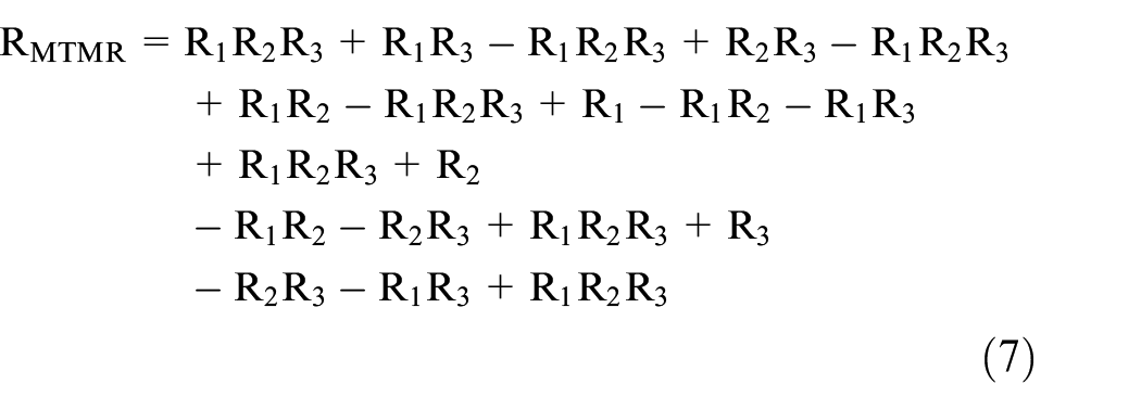

Let R1 = R2 = R3 = R


The overall reliability of the DR and MTMR systems can be calculated using equations (5) and (10) respectively. For R = 0.9, we get 0.99 reliability for the DR system and 0.999 for the MTMR system. We can see that the reliability of the system has increased with the proposed MTMR hardware redundancy scheme in the speed control system.
Mathematical model of separately excited DC motor
Figure 3 shows the mathematical model of a separately excited DC motor employed in this study.
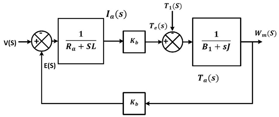
Mathematical model of separately excited DC motor. 6
The following mathematical equations are used to create the mathematical model illustrated above.

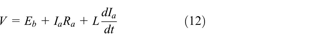


The symbols used in these equations are defined in Table 1.
List of parameters and symbols for DC Motor.

Speed control of separately excited DC motor
A Pulse Width Modulation (PWM) generator is used at the gate of switches for the speed controlling procedure. Figure 4 shows the waveforms of 0%, 20%, 50%, 80%, and 100% duty cycle to change the speed accordingly. When the PWM signal is given to IGBT_1 (SW1) and IGBT_4 (SW4), the current will follow the path from Vs to Ground rotating the motor in the forward direction as shown in Figure 5. If PWM applied to IGBT_1 (SW1) is changed then motor speed may vary. Similarly, when the PWM signal is applied on IGBT_2 (SW2) and IGBT_3 (SW3), the current will follow the path from Vs to Ground rotating the motor in the reverse direction. We are controlling the speed of the DC motor by using the PWM signal to turn it on and off at a specific moment.

PWM waveforms of duty cycle. 1
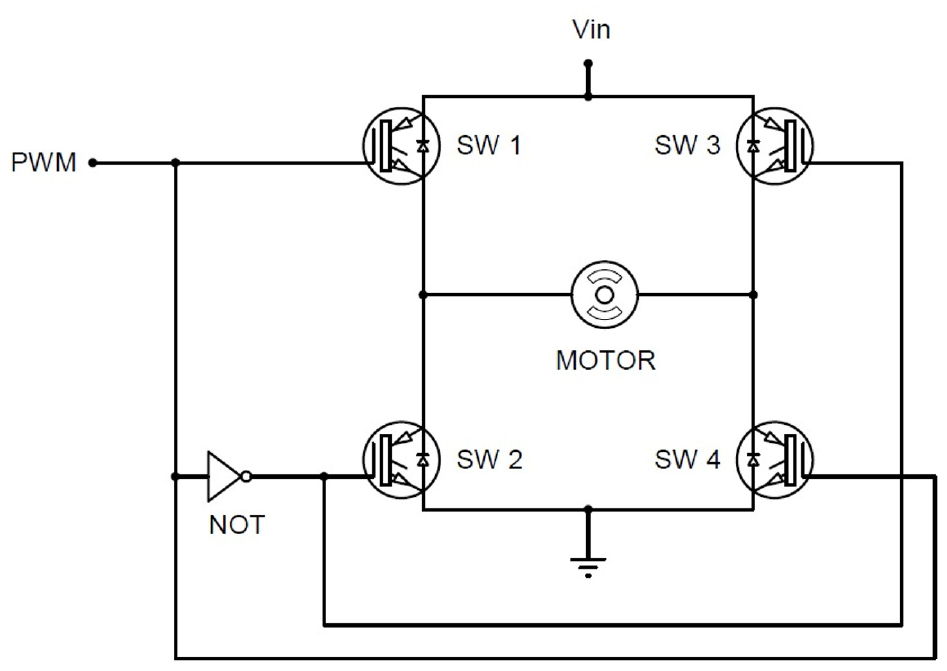
A simplified H-bridge with PWM signal. 6
Literature review
A fault-tolerant control technique for Cascaded H-bridge rectifiers is provided in Iman-Eini et al. 7 Redundancy is the fault-tolerant system’s proposed strategy proposed by Iman-Eini et al. Because cells of all H-bridge are the same, Cascaded H-bridge rectifiers are ideal for attaining this purpose. One Cascaded bridge is added parallel to the bridge rectifiers as a backup to ensure that the converter continues to function even if one of the bridges fails. Redundancy is obtained if the cell of the H-bridge containing the defective component can be bypassed, preventing a cascade failure and allowing normal operation to continue.
Patel et al. 8 proposed a fault-tolerant framework for the Cascaded H-bridge multi-level inverter with three phases in their paper. If one of the three modules fails, the other two healthy modules will continue to supply output voltage with the same amplitude and voltage level when all three modules are working well. As a result, the suggested fault-tolerant structure of the Cascaded H-bridge multi-level inverter increases system performance by avoiding the entire system from failing even if one of the three modules fails. Dos Santos Moraes et al. 9 extended the research by comparing different control systems for similar structures under two fault scenarios: a system with an open phase of the machine and a short-circuit of an inverter’s switching. To maintain the system operation in the event of simultaneous faults in any two sensors, the MTMR sensor assembly for proposed for air-fuel ratio control system sensors in Amin and Mahmood-Ul-Hasan. 5
In article, 10 the suggested technique by Xiao et al. takes advantage of the maintaining an active switch in the damaged Submodule (SM) to gain additional output voltage level, resulting in greater line-to-line voltage, particularly when many types of SM defects are present at the same time. A new failure controls strategy for the Cascaded H-bridge multi-level inverter is suggested in Ouni et al. 11 by utilizing the maximum effect caused by the pure sine wave PWM switches technology. The suggested solution can increase the Cascaded H-bridge maximum multi-level inverter voltage supply in malfunctioning settings.
The study 12 proposes a fault-tolerant control in which the fault diagnosis and isolating component employ a machine learning observation approach for fault identification, separation, and reconfiguring. In terms of maintaining the air-fuel proportion in malfunctioning circumstances, a fuel regulator is installed in the fuel supply lines and a proportional control loop is built. Redundancy in the sensor and fuel actuators is adopted in Amin and Mahmood-ul-Hasan 13 to prevent the engine cutoff in the event of simultaneous failures in several sensors and to prevent a single point of failure owing to an actuator malfunction. The article 14 proposes an FTC approach for H-bridge inverters with current tracking based on voltages vectors equivalence substitutions.
A novel fault-tolerant approach for a multilevel inverter is given in Moamaei et al. 15 to boost the inverter’s dependability. The mechanical structure of the inverters is modified with the insertion of some different elements, preventing inverter interruption in the case of various problems. The voltage level of the inverters is decreased using this procedure, which involves bypassing the damaged unit and substituting it with a secondary H-Bridge unit. The inverter performance in the malfunctioning state is identical to that in the continuous state.
In Riaz et al., 16 the authors provide a brief overview of Sliding Mode Control (SMC) types, techniques, and applications in the subject of FTC. It also discusses the transient response, sliding process, and sliding surface, as well as its benefits and drawbacks. H-Bridges multi-level inverter with polarization converter offers superior dependability as mentioned in Vyas et al. 17 and less complication than another redundant multi-level inverter due to the lower total amount of regulated relays. In this research, a backup switching is necessary to remove the damaged switches, and this switch is referred to as a crucial switch.
A unified FTC technique is proposed with both hardware and analytical redundancy techniques in Amin and Mahmood-ul-Hasan 18 for air-fuel ratio control system sensors and actuators. Speed control with H-bridge has been presented in MathWorks, 19 in which redundancy can be incorporated for continued operation during fault scenarios of switches. A fault-tolerant technique is needed to detect and protect malfunctioning switching devices, preventing the entire system from shutting down. 20
In the previous dual redundant H-bridge system, 3 if a fault occurs in both switches, the whole system will shut down due to which huge power loss occurs. To overcome this issue, we have proposed an MTMR-based system with a unique combination of analytical redundancy architecture in the control system for fault detection, isolation, and reconfiguration. Because a normal TMR cannot offer an output in the event of simultaneous faults in two channels, we have proposed an advanced MTMR scheme for our speed control application. The proposed MTMR will still be able to provide output with only one healthy switch with the other two in the faulty conditions. It makes the work more efficient and more reliable decreasing the effects of faults to a minimal point. For this proposed system, MATLAB/Simulink software was used for the experimentation process and to check the demonstrated events of faults while maintaining the speed of the motor. The presented work establishes that the MTMR-based fault-tolerant H-bridge with the FDI unit is a highly reliable solution for the speed control of a separately excited DC motor. The comparison of the proposed work with existing works also demonstrates its superior performance for reliable fault-tolerant speed control of the DC motor.
Further contents of the paper are organized as: Section 3 consists of the Research Methodology, Section 4 consists of Results and Discussions, and Section 5 consists of a Comparison with previous reference paper. The last part contains the conclusion with future recommendations.
Research methodology
The implementation of a Separately Excited DC motor along with an H-Bridge was already done in MATLAB/Simulink. 19 We have implemented the proposed MTMR scheme for the H-bridges on this model to increase its reliability. The schematic diagram of the proposed system is shown in Figure 6.
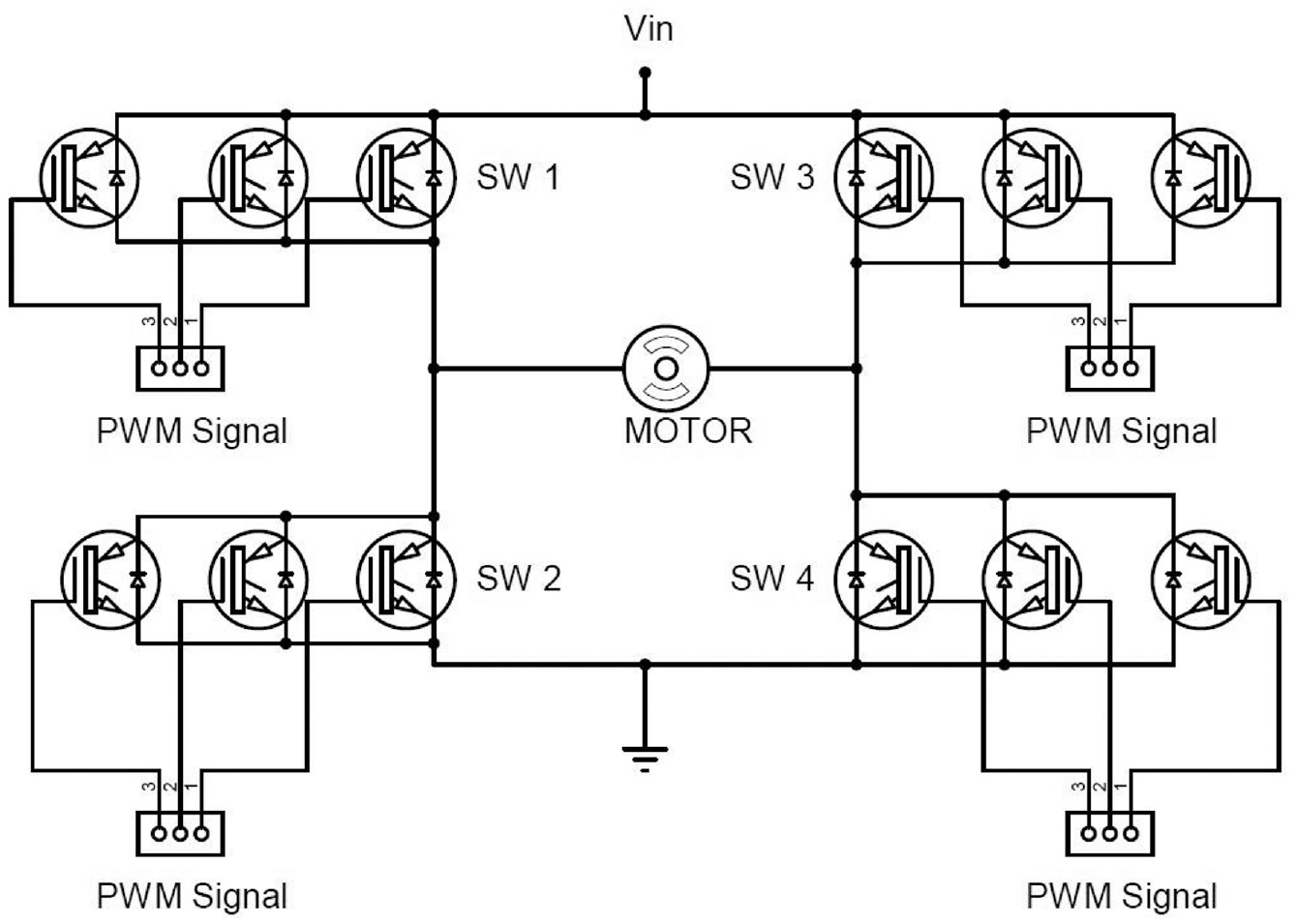
Schematic diagram of the MTMR H-bridge system.
The flowchart of the proposed system is mentioned in Figure 7. The operation continues to move normally until the primary component is healthy and is working perfectly. As soon as there is some error caused in the primary component, the backup component takes the place of the primary component and the system moves normally without any loss and interruption. By using the MTMR scheme, we can easily remove the single point of failure. For H-bridge, 12 transistors would be used where four transistors will operate as primary switches meanwhile the rest of the eight transistors will be used to provide the backup as shown in Figure 7. In normal circumstances of process, all three points give voters their results and voters decide which output is offered to the DC motor for speed control. However, if any error occurs in any transistor, the corresponding voter cuts out its connection from the drive and uses other redundant transistor switch to control the speed of the separately excited DC motor.

Flowchart of MTMR fault-tolerant H-bridge.
The MATLAB/Simulink implementation of the proposed system with the control circuitry is shown in Figure 8.

Proposed fault-tolerant MTMR H-bridge system.
In the proposed model, we used Fault Injection Unit (FIU) to inject the faults into the system. The switch error in the system is represented by (0) and (1) represents the healthy switch as shown in Figure 9. There are four redundant blocks within the FDI unit whose purpose is to perceive errors within every IGBT switch.

FIU and dashboard of scopes.
The FDI unit developed in this work is shown in Figures 10 and 11.

Fault detection and isolation unit.
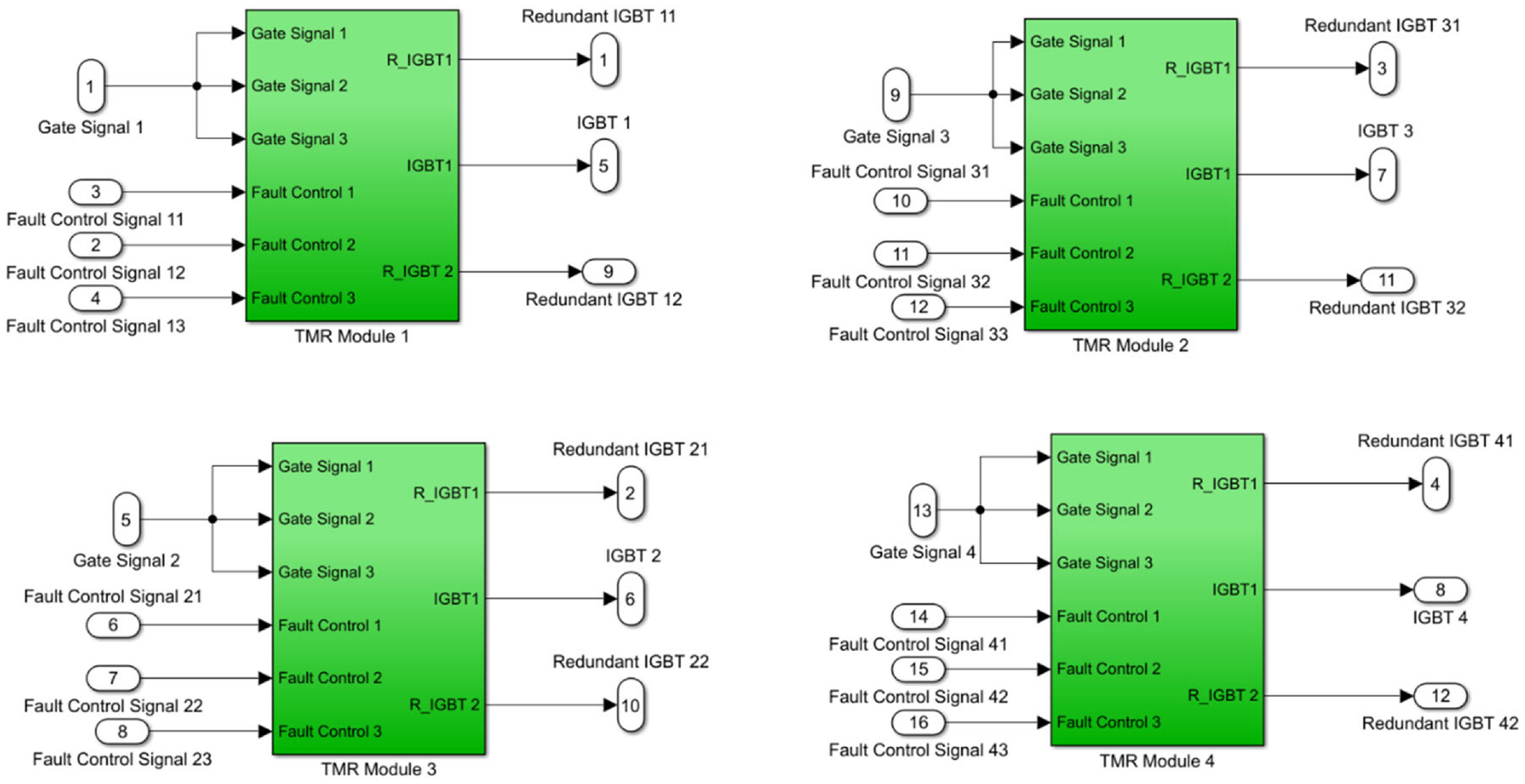
Architecture of fault detection and isolation unit.
The FDI unit contains 12 inputs and each is connected with the IGBT along with producing three outputs, that is, IGBT, IGBT_1 (Redundant IGBT 1), and IGBT_2 (Redundant IGBT 2). Under normal circumstances, the IGBT is getting healthy signals and the switching system performs well. However, the activities of the system become entirely different from their normal function when an IGBT experiences a fault. When any fault is inserted into any switch with the help of FIU, the FDI unit detects the abnormal activity of the switch with the help of a fault detector and stops providing the signal at the gate of a faulty switch due to which the switch is separated from the system. Voltage measurements at the output terminals are used for fault detection and isolation purposes.
In the proposed MTMR system, the FDI includes six inputs. Initially in the start when our main IGBT_1 is active and working perfectly, Redundant IGBT_1 and Redundant IGBT_2 are off. Gate signal 1 is utilized on the main IGBT. When a fault is injected in the main IGBT with the help of FIU, the system cuts off the faulty switch and sends the power toward the redundant IGBT_1 to maintain the entire system functionality. If any fault appears in the two switches simultaneously, the proposed system will continue to operate with a single last standby redundant IGBT_3. However, this will not be possible in a regular TMR system and it will collapse in the event of simultaneous failures of two switches. Therefore, the proposed MTMR H-bridge scheme is more reliable than a regular TMR.
The limitation in our work includes an increase in the weight and size of the system which will automatically increase the power losses and cost of the system. However, for applications demanding high reliability and safety, these drawbacks can be tolerated. The proposed work was performed with a constant speed as the limiting case. Load variations and sudden reduction of speed scenarios due to shutdown are not considered in the study.
Results and discussions
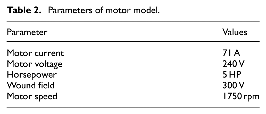
The proposed model is simulated on a 100% duty cycle to provide 240 V to the DC separately excited motor. The motor rotates clockwise with a maximum of 1750 rpm as shown in Figures 12 and 13. when the motor starts, it draws a high inrush current to reach its highest rotational speed however, after a while, the currents start to slow down and become constant due to the constant speed of the motor. For measurement purposes, two scopes are utilized. The knowledge about the motors’ rpm, armature current, and weight torque is provided by scope 1, and the information on IGBT as well as diode current is provided by scope 2. The parameters of the motor model used in the study are provided in Table 2.

Voltages of the motor at duty cycle 100%.

Speed of motor and armature current at duty cycle 100%.
Parameters of motor model.
An armature voltage control module is used to move the motor in the reverse direction. The direction can be reversed by changing the step size of the signal provided. If we set the time of step size to 0.5 s, it will take 0.5 s for the voltage of armature in the reverse direction. Then DC motor will start to operate in the reverse direction from +1750 to −1750 rpm. Likely, the polarity of voltage provided to the motor will change from +240 to −240 V.
The current and voltage profile of the IGBT 1 in normal working conditions are shown in Figures 14 and 15, respectively.

Current of IGBT 1 at duty cycle 100%.
Voltages of IGBT 1 at duty cycle 100%.
Now the fault tolerance performance of the proposed system is tested by injecting faults in IGBT1, first standby IGBT_11, and finally last redundant IGBT_12 with the help of FIU. When we manually inject fault at 100% duty cycle with the help of a switch as presented in Figure 16, voltages of motor drop. But in some milliseconds, our redundant_IGBT_1 takes over it and prevents faults in the system. Similarly, if IGBT_1 fails due to some reason, redundant IGBT_2 takes place within no time, and the system keeps operating without failure.

Voltages of the motor during faults of IGBT_1 and IGBT_11.
Likewise, when our primary switch becomes faulty, the motor rpm of 1750 deviates from its set position but as soon as IGBT_1 takes over, the motor speed comes back toward its normal rotation as presented in Figure 17. The input surge current also deviates when the system fails but it also comes back to its normal state when IGBT_1 takes over the system.

Speed of motor and armature current during faults of IGBT_1 and IGBT_11.
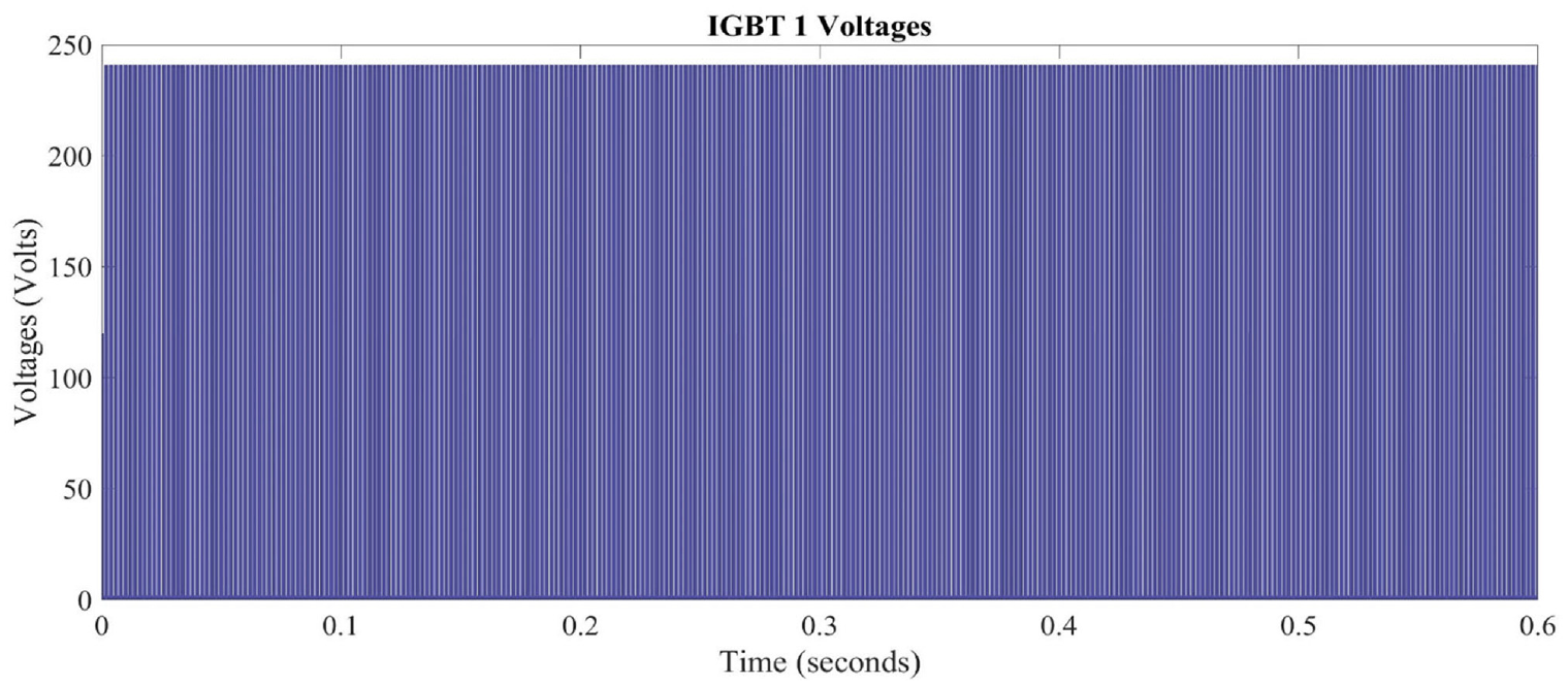
The switch over of the standby switch with a faulty one is represented in Figure 18. The redundant switches and primary switches have the same voltage so they are shown in the same graph. The FDI component separates the faulty IGBT and replaces it with the standby IGBT_1 by providing it with a gate signal. Then the fault is again injected into the IGBT_1, and it is replaced by the third standby switch IGBT_12 and maintains system operation.

Voltages of IGBT1 during faults of IGBT_1 and IGBT_11.
The current profile of the IGBT 1 switch during faults in primary and first standby is shown in Figure 19 which clearly shows the system can continue performance in the event of simultaneous failures of any two switches of the MTMR switch assembly.
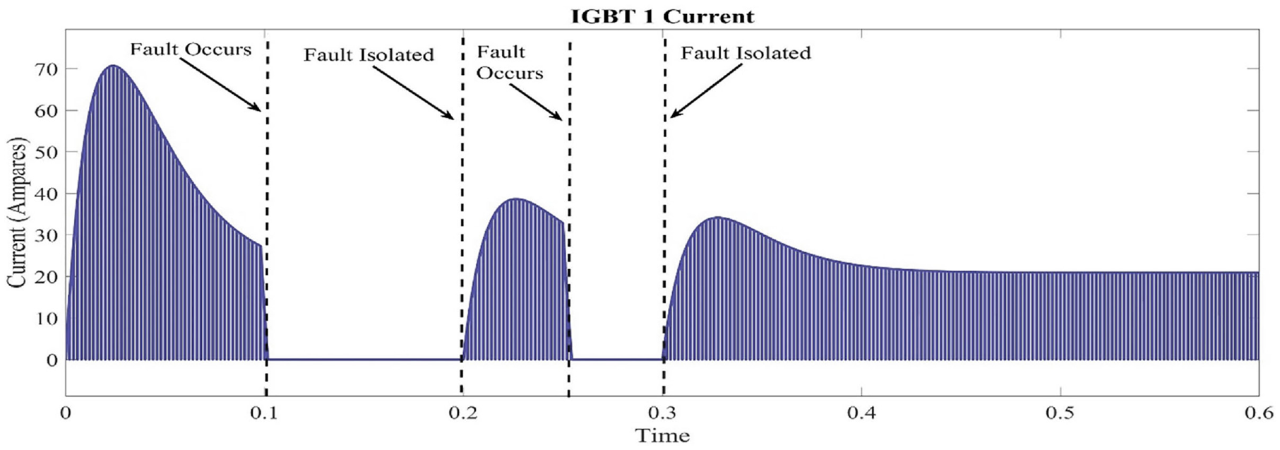
Assembly current of IGBT1 during faults of IGBT_1 and IGBT_11.
Now the fault is injected into all switches and the results of the current profile are shown in Figure 20. In this scenario, the system has collapsed in which motor current and IGBT1 current become zero and gradually RPM of the motor approaches zero.

Assembly current of IGBT1 during faults of IGBT_1, IGBT_11, and IGBT_12.
Comparison with existing works
A comparison of the proposed highly reliable speed control system has been performed with the existing works in this section. It was seen earlier that MTMR has increased the reliability and efficiency of the system due to three redundant switches. It has reduced the chances of a breakdown in the system by providing alternative IGBTs for continuous process. The previous model 3 was based on DR in which the system will collapse in the event of failure of both switches. However, the proposed MTMR-based H-bridge can continue operation in the event of failure of any two switches simultaneously thereby increasing the reliability of the overall system. This has also been demonstrated with simulation results shown in Figure 21. A comparison of two previous and advanced models is given in below Table 3.
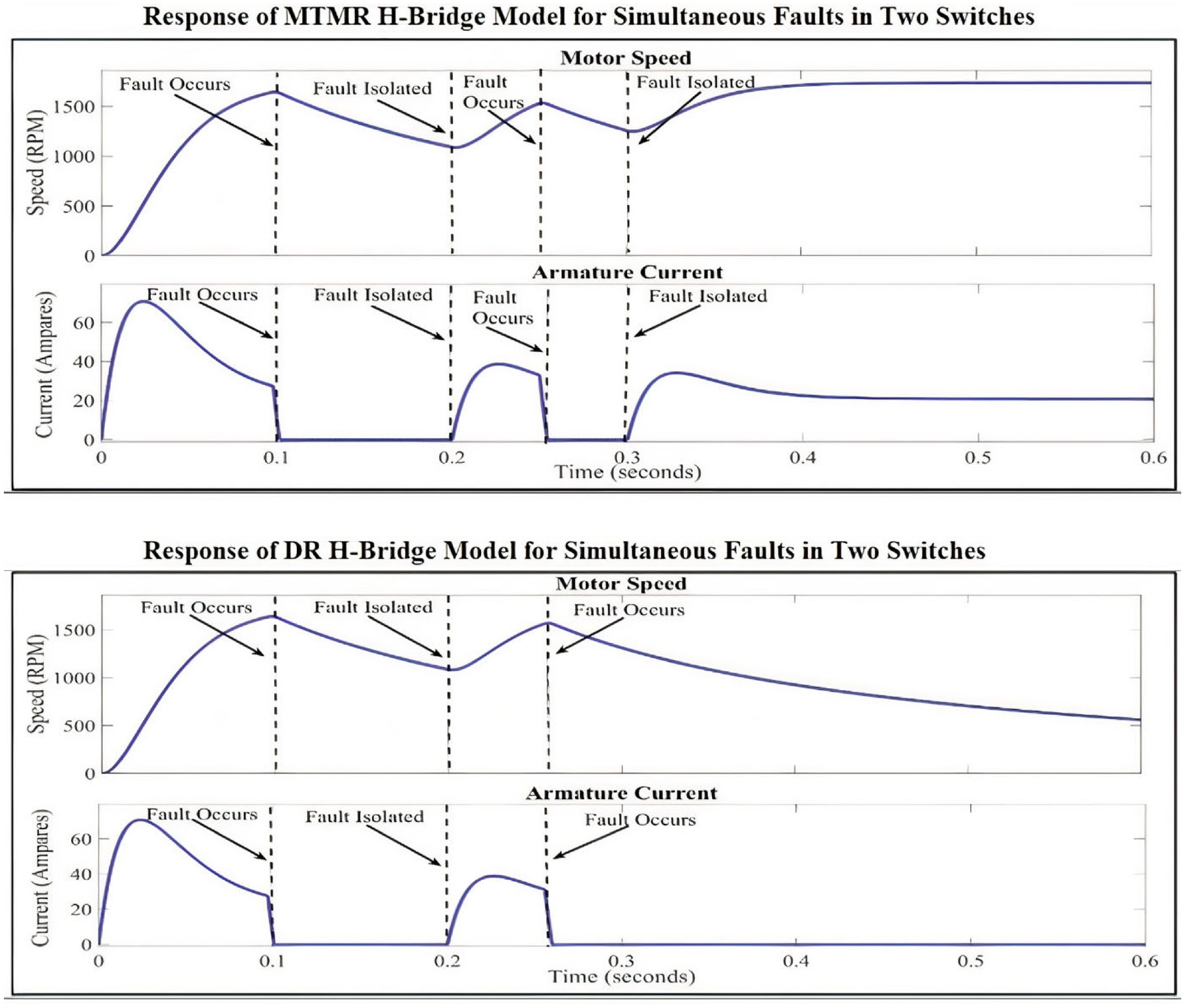
Comparison between DR and MTMR models.
Comparison of previous and proposed advanced model.

The authors Shi and Zhang, 21 investigated steering actuator malfunction detection using a model-based support vector machine (SVM) classification approach with a grey wolf optimizer. The defect was diagnosed using the data-based SVM classification method. The proposed approach was found excellent yet with the computationally high cost to be implemented for low-cost controllers. The proposed solution based on both FDI and hardware MTMR architecture presents a simple yet effective approach for a highly reliable speed control system of a separately excited DC motor.
Conclusions
This paper presents an MTMR-based fault-tolerant control system that can easily detect a fault in any IGBT with the help of a dedicated FDI unit. After detecting the fault, it isolates it and in replacement adds up a redundant IGBT to keep up the performances of a separately excited DC motor. Because a normal TMR cannot offer an output in the event of simultaneous faults in two switches, we have proposed an advanced MTMR scheme for our speed control application. The proposed MTMR will be able to provide output with only one healthy switch with the other two in the faulty conditions. The simulation results in MATLAB/Simulink environment demonstrated in the faulty situation, armature current, IGBT current, rpm, and motor voltages lose the initial state due to fault but as soon as redundant IGBT takes place, all the parameters become stable again. The system failure was caused only in the case of simultaneous failure of all three switches of the MTMR assembly. This study shows that the MTMR-based fault-tolerant H-bridge is a very dependable solution for separately excited dc motor speed control since it has prevented the system from failing in case of simultaneous failure of any two switches of the assembly. The comparison of the proposed work with existing works also demonstrates its superior performance for reliable fault-tolerant speed control of a separately excited DC motor.
Future work may include implementing the given system physically on hardware and considering the hardware delays in the switching process and minimizing all such delays to improve the accuracy and efficiency of the system.
Footnotes
Appendix
Handling Editor: Chenhui Liang
Declaration of conflicting interests
The author(s) declared no potential conflicts of interest with respect to the research, authorship, and/or publication of this article.
Funding
The author(s) received no financial support for the research, authorship, and/or publication of this article.