
Abstract
Leaf spring experiences frequent cyclic loading during working conditions. When design stage itself it is very essential to assess the fatigue life of the suspension system. It is important to consider and evaluate the key aspects of fatigue failure and life by using Finite Element Analysis (FEA) techniques to overcome these failures. This paper serves to stimulate the premature failure of the existing and proposed bracket model with generalized force elements under dynamic load conditions. Scanning Electron Microscope (SEM) was used to identify the bracket failure prone areas which indicate that the cyclic load in the suspension system is caused by rural area road-induced vibrations and bumps. This contributes to the increase of the fatigue fracture, which ends up with a bracket failure. The results indicated that the fatigue life of existing bracket is low for rough road conditions; the modified bracket has been optimized for the safe load conditions of the heavy vehicle suspension system
Introduction
The suspension system that provides occupants with convenient for safe driving and protects a vehicle against damage. The suspension system was intended to isolate the vehicle from extreme road conditions. The performance of suspension systems requires several levels to determine an acceptable measurable standard. 1 A suspension requires high damping and rigidity to achieve greater stability, whereas a soft spring requires, low damping is more for convenient riding. 2 The damping coefficient can be reduced in off-road conditions to improve smooth operation. The handling of flat roads with strong damper could be improved. Also, active suspension systems that take away a damaged suspension design by the active provision of the required stiffness between the wheel and chassis. Such suspensions, however, are more costly and complicated. An air suspension system for altering the stiffness for a steady load was conducted a few tests. 3 These systems operate by changing the air springs “gas volume.” The compressibility of air suspension in a pneumatic source ensures stiffness. The air pressure is usually three bar static and is not higher than 7–8 bar. 4 The airbag’s strength is the effective airbag area, which is increased by the air pressure. The powerful section of an airbag is not completely stable in terms of its tension and compression the suspensions are costlier and morecomplicated. 5
Failure damage assessment of a vehicle is an important role in the design stage. The failure analysis is used to replace the defected component to the existing problem. A significant role in the design process is to determine a vehicle’s failure influence. Failure is unpreventable to prevent failure. This type of load interactions can lead to a significant acceleration or delay in a crack growth cycle. The tensile over delayed load cycles and under compressive load increased the development of fatigue crack. 6 Fractography must be analyzed by the SEM technique for failure analysis. 7 The performance of vehicle components such as air suspension; it relates to vehicle safety. 8 The fatigue life of air suspension systems will be predicted using an S-N method. 9 The time and low-cost savings associated with this calculation were actively developed using a simulation model to test component fatigue control. 10 Materials research advances lead to new materials and composites are one of those new materials. Materials used for making the component are substituted for materials and are called composites. 11 The composite suspension system is made of Glass-fiber reinforced plastics (GFRPs) because they fulfill the vehicle suspension specifications. 12 Such products give the benefit of significant weight loss without compromising ability. 13 In the case of wet operations, composite materials are very likely to fail as they tend to absorb moisture which affects their mechanical properties and dimensions. 14
This paper describes the candidate research product is LPT 1613 TCIC suspension model developed by automotive industries. Using Finite Element Analysis, visual inspection, Scanning Electron microscope (SEM), the failing of Leaf spring and suspension bracket has been examined. The crack on the bracket has been observed by a Scanning Electron Microscope (SEM) in higher magnifications.
Experimentation
When the system is powered by force bellows, a leaf spring absorbs the shock. The bellows on one end of the leaf spring and suspension bracket is mounted at another end. Thus, any moment the system force is exerted, the leaf spring and bracket absorbs the shocks. The same process was repeated when the vehicle is moving because of the irregularity of the road. Owing to repeated cyclic process bracket goes under fatigue. It results in the formation of cracks and bends in the leaf spring and suspension bracket. Bending of the bracket associated with the spring area and the crack formation of the bracket area along the side of the frame. The defective leaf spring and bracket is suspected failures because of fluctuating loads with uneven road surface conditions. Also, an identification of the material composition is the essential phase in failure analysis.
Figure 1 shows the typical suspension system assembly which in the heavy vehicles. Composition of materials used in suspension components for 50Si2Mn90. The materials are in hardened and tempered condition. Table 1 shown the findings of leaf spring and bracket material chemical compositional are analyzed.

Typical suspension assembly.
Material composition.
Dynamic forces calculation
When analyzing the system forces, considered dynamic forces such as brake load, bump load, corner couple, bump couple, and corner pretensions operating on the leaf spring bracket. The motion only considers horizontal acceleration for the braking experience of vehicles on the road level. According to Newton’s motion laws, the sum of the vertical forces acting on the body must be zero. The vertical forces and normal forces of the vehicle on the road push the wheel against the gravity pulling down. Balance is effective in the center of gravity of the vehicle (C.G).The motion only considers horizontal acceleration for the braking experience of vehicles on the road level. According to Newton’s motion laws, the sum of the vertical forces acting on the body must be zero. The vertical forces and normal forces of the vehicle on the road push the wheel against the gravity pulling down. Balance is effective in the center of gravity of the vehicle (C.G).The center of gravity, N1&N2 normal forces, and f1 and f2 braking forces, along with the horizontal braking force on the route of the wheel. The weight (W) and the force of gravity constitute the weight, when the normal forces function as N1 and N2 on the front and rear axle, then the Newton equation is applied,

During the vehicle motion, there is no appreciable forward rotation. As Newton’s law is implemented, it must also add to zero the amount of the torques (lever arm strength). Once the center of gravity is used as the pivotal point, the normal and vertical force of the road acts on the front wheel produced a torque in the clockwise direction with a b1 lever, as seen in the figure, while the normal force at the rear wheel produces a torque in the counter-clockwise direction b2 (note that b1 + b2 = B, the wheelbase). The braking forces act on the front and rear wheel develop counterclockwise torques with lever arm h, the height of the C.G from the roadway. Adding clockwise torques and subtracting counterclockwise torques (where f1 and f2 are Coefficients of friction).

These two equations are solved for normal forces (N1, N2) with the following results:


When a wheel hits a bump, the load imposed on a vehicle is harder. This load is called Bump load, if the vehicle is moving, irregularities like speed breakers fall on the road. Therefore, the wheel axle carries more load as the vehicle passes over this imbalance due to dynamic forces. Such forces are converted into a suspension system. In this case, a significant number of loads must be moved from the suspension system. Considering the implications of the following variables shown Table 2 the load acting on the brackets.
Specification of suspension system.

When brakes are applied in a vehicle around 60 percent of sprung mass exerted on the front axle generating two forms of couples, like bump couple and angle pair. In the two instances, one side of the wheel moves force to the other side of the wheel. When one end of the vehicle loses weight, the other end absorbs the normal couple load of this phenomenon by using the ground surface.
Results and discussion
Finite element analysis
A complete solid leaf spring and suspension bracket model was developed using Solid Works software to carry out this analysis. The model is imported in ANSYS18.2 in the form of the IGES format. Static structural analysis of the problems using finite element analysis was completed by considering SOLID 45 element preferred with proper meshing. The total element number of the mesh element is 72,802, and 58,3216 is the node. The element is defined by three degrees of freedom with each node. If leaf springs could initially work well, they continually fail in operation due to fatigue failure by cyclic load. The aim of the fatigue analysis is to evaluate the ability of the material to withstand a number of cycles during its lifetime. The fatigue analysis was based on a stress-life approach to evaluate the leaf spring fatigue life. The static condition takes into account the existing load conditions by using boundary conditions. The chosen material for the analysis has mechanical properties, like Young’s modulus of 206 GPa, Ultimate tensile strength of 420 MPa, Fatigue strength 275 MPa, and Poisson’s ratio of 0.3. The leaf spring dimensions are number of spring leaf (n = 6), span length (2L = 1340 mm), leaf thickness (t = 12 mm), leaf width (b = 70 mm)). During analysis a 10500 N is assumed to be applied on the spring, with an allowable deflection.
Figure 2 shown fatigue life and Factor of safety and stress of the leaf spring was observed with respective load condition. The result shows improved in fatigue life of leaf spring suspension system. From the fatigue analysis, the leaf spring was found to be greater life an under dynamic load conditions. There is a safety factor in terms of fatigue failure in the resulting design life. It shows a maximum of 15 safety factors values less than 1 indicate failures before the product life of the fatigue risk factor. The final results show the leaf spring design to use safely. The fatigue life of the model shows that the fatigue life is 40,618, comparatively more than the existing model’s fatigue life, which is more prompt for use in different load conditions than the leaf spring suspension.

(a) Fatigue life, and (b) safety factor.
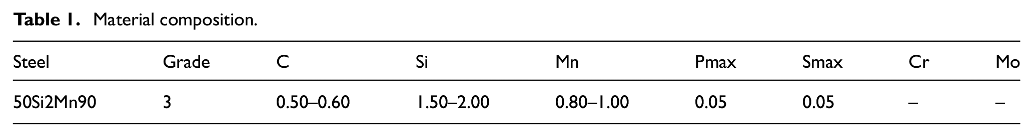
The results for the existing bracket with all the parameters in the ANSYS18.2 software were obtained under different load conditions. Figure 3 shown the stresses of von-Misses on the bracket, which are induced by dynamic force, including brake load, bump load, bump couple, corner couple and corner pretension.
FEA results of without rib: (a) CAD model without rib, (b) brake load, (c) bump load, and (d) bump couple.
Improvement in existing bracket model
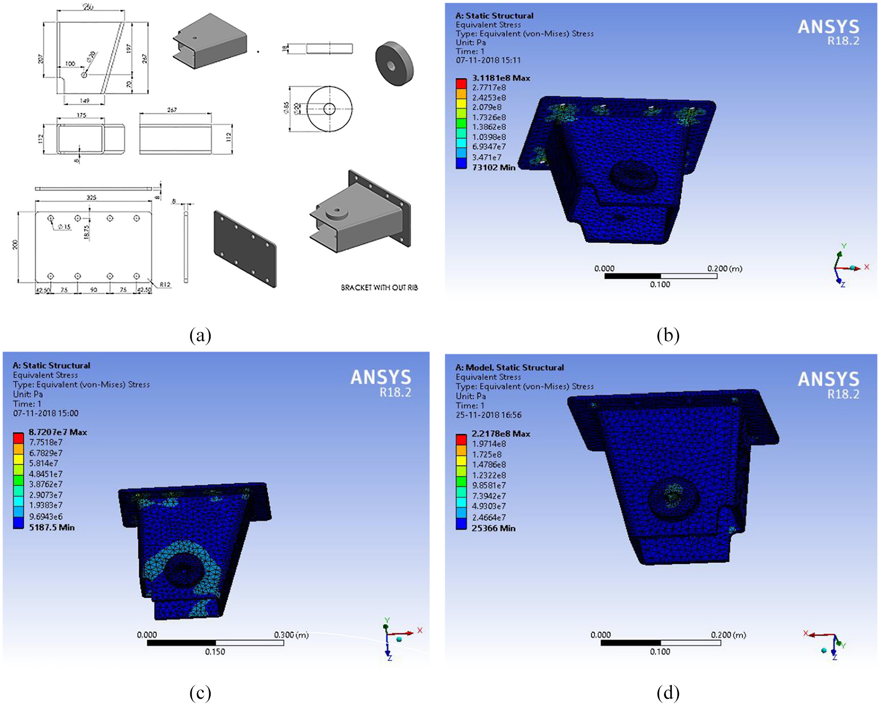
The safe stress value of the shackle bracket should be increased to enhance the existing model. This would lead to material transition and lead to difficulties in maintaining an inventory for designing new materials. Furthermore, this design change does not affect the existing vehicle operation. Ultimately, the concept of inserting ribs on the side of the bracket was conceived without changing the material and operation. The addition of the support would enhance the stress distribution. For the stiffener certain constraints are taken into consideration, as all areas are covered by fasteners if the stiffeners are placed between the holes, it would prevent the bolt from connecting to them. The optimal places to add stiffener should also be analyzed. The height of the stiffeners is determined and the analysis for the existing analysis is completed. The calculation of all parameters and the input condition in every case was similar. For the same process, the existing values can be used. The findings obtained in the existing bracket design demonstrate clearly that the original system needs to be strengthened. The results for different loading conditions of the proposed bracket are shown below Figure 4.
FEA results of with rib: (a) CAD model proposed bracket, (b) brake load, (c) bump load, and (d) bump couple.
The factor of safety reduces the uncertainty in the design process, such as calculations, materials strength, cost, and quality. The number chosen as the safety factor depends on the materials and use of the component. From the Table 3 and Figure 5(a) and (b) showed Factor of safety, life, and stress of the bracket is observed with respective load condition. The graph shows improved in fatigue life of proposed bracket compare to existing bracket
FEA results for bracket.


(a) Stress versus load factor, (b) load vs factor of safety, and (c) S-N curve.
Life cycle calculation
Fatigue investigation is referred to as the method of initiation of the crack, typical in terms of total life (S-N or nominal stress), initiation of the crack (E-N), and growth of the crack, which involves the number of cycles up until the fracture. In fatigue studies, two cyclic stress or strain areas are mainly found, such as low cycle fatigue and high cycle fatigue. The fatigue evaluation method contains material, loading, and geometry details and analysis and results. The load transition is so essential to perform a precise estimate of fatigue life. Under loading subjected to high cycle fatigue which exhibits elastic stresses where the total fatigue life of the spring is achieved. 15 These loading could be defined by recurrence or continuum in different ways depending on the study method of fatigue. When dealing with finite component models, the load applied can be force, stress, temperature, displacement. The time history of fatigue calculation should be the variation of the FEA loading time. 16 Similarly, in modeled conditions, it is necessary to ensure the S-N data applies; instead of local stress, most S-N curves are for nominal stress. Analyze the contribution of each cycle to damage by reference to the selected damage curve. The Relationship between Hwang and Han occurs. 17

Where ni is the number of cycles failures,
B = 10.33; C = 0.14012; R = σmax/ σouts, r = Applied stress level = 0.33
Failures to number of cycle, N = 10,00,000 (Approx.) For each life-cycle evaluation, the S-N curve is a prediction. In the S-N curve, the X-axis shows the product no life cycle at various stages. The Y axis shows the individual stress values. Comparing the stresses, the life cycle of each product could be estimated. Figure 4(c) revealed ten lakhs failure cycles in the leaf spring model. Therefore, the leaf spring model consisting of 50Si2Mn90, under the stress level of 0.33 with nearly 10 Lakh cycles is inferred from the Hwang & Han relationship. Since this test involves peak amplitude and minimal cycles of fatigue analysis, the studies not list any final solutions for this short period.
From Table 4 shown the various prospects of improving the life cycle of the Leaf spring bracket is concentrated finally the inclusion of stiffeners in the section gives the increment in the number of cycles in the bracket without upsetting the Fit, Form, and Function.
Comparison of results.

Visual analysis
The next step was the visual inspection approach for the defect leaf spring bracket. The visual examination revealed a fractured of the fixed chassis area and bracket bends in the area linked to the leaf spring. A typical cyclic load was observed when analyzing the fractured area. The outcome is a crack close to the fixed portion of the bracket. Because of fluctuating loading results in failures of a part bend in a leaf spring-contact area, the crack traces markings were nucleated and propagated along the surface. Even if damaged parts rust, it should result in corrosion on the leaf spring bracket that has been finally damaged as shown in Figure 6. FEM static examination of the bracket model was made in the exploration are reported in this paper. The deflection and stress under various load conditions influence the life of the suspension framework.

Fractured part of the bracket.
In the study of the finite element, were noted that the overall stress on the existing design can be reduced and minimized with the modified design. The findings of this investigation to ensure that the safety factor, reliability, and displacement result are improved even under dynamic conditions. At the end of this study, improvements were proposed for the design, so the optimized shake bracket design is a cost-efficient solution. Because of this objective, the existing bracket model has been modified economically and feasible in order to avoid frequent failure.
Fractography
In this paper, the failure examines used evidence of surface fracture, irregular fracture structure, stress analysis, and fracture mechanics to determine points in time for an automotive suspension bracket sequence failure event. This study resulted from a wider investigation into a loss in control accident when both the suspension bracket and the rear axles were found fractured after the incident. The fractured part examines the internal structure and spatial distribution of elements in metal alloys. The sample was prepared through rough and fine polishing during this stage and the specimen was then etched for observation with two percentage points of the metal solution. Scanning Electronic Microscopy image of the damaged portion was examined.
The visual evaluation and study of the fractures by means of SEM images as shown in Figure 7 shows the cyclic loading-induced cracking. In particular, the fatigue crack spreads on surfaces due to varying stress in specialized parts. Slip steps, assembly, surface defects, defects, etc., could cause the beginning of the surface crack to concentrate stress. The stress is due to the sudden changes in their cross-sectional area due to stress concentration. The reduced cross segment could indeed cause a residual crack with increased stress. The consequent, premature crack closures, micro structural homogeneity, pressure versus strain on the plane (indoor surface Vs) and macro plasticity record irregular behavior. For materials which are ductile often cracks are nucleated because of plastic deformation. When it strikes inclusions or grain boundaries and unexpected sharp twisting or turns the splits along the slip bands decrease. Such formed cracks show a smooth propagation and normalize to stress direction. A certain type of behavior can be seen in many more materials in normal nucleated splits. 18

SEM image of bracket: (a) crack initiation micro graphs, and (b) crack progated regions.
The images of the SEM microstructure reveal the crucial fatigue crack that is the porosity. Fatigue resistance to crack initiation could be reached using non-shearable porous particles, free of phases, with a small crystallized or an unrecrystallized structure of grain. Figure 7(a) SEM revealed that 70% of the mid-plane surface area was a deeper secondary crack at this location. The microscopic defect becomes larger under the effect of corrosion. The extension direction of fatigue crack can be clearly observed (see Figure 7(b)). Crack begins at certain point and expands into specimen interior. The direction of crack propagation is indicated by arrow marks. It is evident from the fracture that almost halfway between the inner surface and the middle layer fracture is a normal region. It is perpendicular to the long axis of the bracket. An existing, spinning crack was seen on the outside of the bracket and reveals the failed bracket surface distorts the deformation priorities from a higher magnification view in Figure 8.The bracket portion which is ductile in nature and fatigue cracks is due to the cyclic deformations near to the crack tip, which connect to the properties of the material and the crack driving force, stress intensity range ΔK. 19

Microscopy image of bracket: (a) crack path, (b) mid-plane fracture splitting, (c) mid-plane rusted, and (d) tempered structure.
The striking findings included the presence of significant secondary fracture splitting in the mid plane and a deep fracture parallel to the steep side of the bracket. As in Figure 8(a), the particular secondary crack fracture could hardly be replicated as it was addressing the bracket surface. Another half of the crack failed to prevent far more work. The consent was never given for finer granularity to break the fracture bracket. The microscopy defect is higher under the influence of corrosion, showing a visible fracture in Figure 8(b) in the mid plane region. The extension path of fatigue crack could be clearly observed (see Figure 8(c)). Crack starts at some level and extends into material interior. The outer half was also observed to have rust relative to the inner half with the existing crack. Exterior surface clearly indicates rusty areas, especially along the broken division, and shows exactly that the intermediate fracture splits around the surface of the outer circumference. As seen in Figure 8(d), this middle – aged crack risk a corroded coating. The difference between the old and the new land was rusty, but less rusty than the previous one. The fracture form could become difficult to see in the existing crack because of corrosion and physical damage and these areas were too evident to reveal substantial micro-measurements. The rupture between the ancient and the mid planes was evident, but the absence range was a duplex and the micro-evils were large. After a microstructure analysis, ferrite over and tempered martensite formation was seen clearly in the specimen.
Conclusion
Structural analysis, of the leaf spring model was most rigid system which achieved a safe stress value having the advantage of intermediate weight. The FEA analysis and metallography study found that the leaf spring failure was not related to a material defect. The results show that the life cycle of the leaf spring with varying loads is enhanced. The visual inspections showed that the fracture occurred at the fixed location of the bracket and also confirmed the inference with the micro-Fractography inspection. This failure investigation reveals that the crack propagates due to the fatigue load when a critical crack length has been reached also the faulty bracket is caused mainly by the fatigue load in the bracket. The deflection and stress values of the modified bracket design would improve the product life cycle without affecting model feature and tolerance.
Footnotes
Acknowledgements
The research study was conducted in the SEM Test analysis in Mechanical Engineering Department laboratory, Government College of Technology at Coimbatore, Tamil Nadu, India.
Handling Editor: James Baldwin
Declaration of conflicting interests
The author(s) declared no potential conflicts of interest with respect to the research, authorship, and/or publication of this article.
Funding
The author(s) received no financial support for the research, authorship, and/or publication of this article.