
Abstract
The major concern of this article is the fatigue failure mechanisms of ceramic cutting tools with the help of intermittent turning experiment and simulation. Finite element simulation was adopted to analyze the spatial and temporal distribution of the stress on the cutting tools. The crack initiation and expansion life in the different positions was researched based on the fatigue crack model. The experiment results showed that the fracture area of flank face reduced with the increase in feed rates, while the fracture area and damage depth of rake face both increased. Through the simulation of fatigue crack, it could be inferred that fatigue fractures were caused by coalescence of cracks. When the feed rate was greater than or equal to 0.2 mm, tool failure was mainly manifested as fatigue fracture of the rake face. And the results of fatigue crack propagation simulation well predicted the cutting tool life. A novel research method for tool fatigue failure was provided.
Introduction
Ceramic tools were often selected in hard cutting process due to high hot hardness and relatively high chemical stability. 1 And dry, hard turning could eliminate disposal cost of coolants. Furthermore, the fatigue life of turned surfaces was large as twice that of ground surfaces with equivalent surface finish. 2 However, the mechanical fatigue cracks and thermal cracks caused the fracture of ceramic cutting tools during intermittent hard cutting process, and the service life of cutting tools decreased significantly, compared to continuous cutting.3,4 Many studies mainly concentrated on the effects of tool material and processing parameters on tool failure in cutting hardened steels.4–7 The tool failure mechanisms differed with the variations in cutting conditions. Furthermore, the final failures of ceramic tools had the characteristics of a typical fatigue crack extension in intermittent cutting. 4 And the fracture area of ceramic tool was mainly determined by mechanical stress, while damage depth was related to thermal stress in intermittent turning process. 5 The graded and homogeneous ceramic tools showed ladder-like fracture under thermal and mechanical shock in the intermittent turning alloy. 6 Specially, Cui and Guo 7 researched the effects of microscopic geometry of ceramic tool surface on tool temperatures in interrupted turning.
However, most of the studies of tool failure focused on the qualitative analysis of the cutting tools failure based on the experiment researches. Failure of ceramic tools was rarely studied quantitatively in intermittent cutting. Using artificial neural networks, the ceramic cutting tool was discovered to worn mostly on the cutting edge within the depth of cut during continuous cutting process due to the relatively high Mises stress. 8 In addition, failure mechanism of ceramic tools was first surveyed in intermittent turning using damage mechanics. 9 Recently, finite element method (FEM) attracted the attention of some researchers in the machining field. A lot of information could be acquired by studying a machining process, which could help researchers to understand failure mechanism of tools and processing law deeply, and so shorten the time for developing new tools and optimize technological parameter. The stress variable rule on cutting tools was investigated to reveal the failure mechanisms based on FEM. 10 Moreover, the effects of key machining parameters on the cutting force and surface roughness were estimated based on FEM.11–14 And both experimental and finite-element-based approaches were adopted to research the effect of coated textured tools on cutting performance. 15 FEM was also used to study deep drawing process of SUS304 cups without delayed cracks, 16 the dynamic process for machining of slip-cast fused silica ceramics, 17 and multi-pass non-axisymmetric spinning of cylindrical parts. 18
However, the lifetime and time-dependent mechanical behavior of composites were determined by fatigue crack extension in most of the practical applications. 19 For ceramics composite, the fatigue lifetime under cyclic loading was much shorter than under static loading. 20 Furthermore, fatigue failure analysis based on FEM has attracted a great deal of attention. For example, due to the complicated stress distribution, a simplified fatigue crack model in core drilling was only used to analyze failure mechanism of polycrystalline diamond (PCD) cutters. 21 In addition, a numerical model in which the specimen was subjected to cyclic tensile loading was generated to simulate the microscale evolution of a fatigue crack in the cutting tool material WC/Co. 22 In product development, the finite element analysis (FEA) was also used to diagnose the fatigue failure of composites; the fatigue life of alloy/ceramic functionally graded materials (FGMs) was investigated based on Paris law using extended finite element method (XFEM). 23 In product development, the FEA was also used to diagnose the fatigue failure of composites. 24 Few study about the fatigue failure of cutting tools based on cutting stress was conducted.
The main aim of this work is to reveal fatigue failure mechanism of the cutting tool in intermittent cutting based on the experiments and simulations. Metal cutting model and fatigue crack model were established. The spatial and temporal distributions of cutting stress on the cutting tools were investigated. Crack propagation analyses at different distances were conducted using the linear elastic fracture mechanics (LEFM).The fatigue life of cracks in the different positions was researched. The simulated fatigue crack path and fatigue life were compared with the experimental results.
Experimental and numerical model
Experimental procedure
The interrupted turning test was carried out on a CKD6150H lathe without cooling fluid. Al2O3-(W, Ti)C ceramic tools were used in the experiments. The cutting parameters are shown in Table 1. Experimental cutting forces were determined using Kistler piezoelectric dynamometer (type 9265A) as shown in Figure 1(a). The cutting parameters are shown in Table 2. The tool nose radius was 0.3 mm, with chamfering angle α = 20° and width br1 = 0.1 mm. The workpiece material was hardened steel 20CrMnTi. The hardness layer depth with 58–62 HRC of surface-hardened steel was 1 mm or so. The workpiece material was processed into long rectangular plates with a thickness of 16 mm and clamped in a cylindrical fixture as shown in Figure 1(b). And cutting time was about 0.193 times of air cutting time. Every experiment was repeated three times under different cutting parameters.
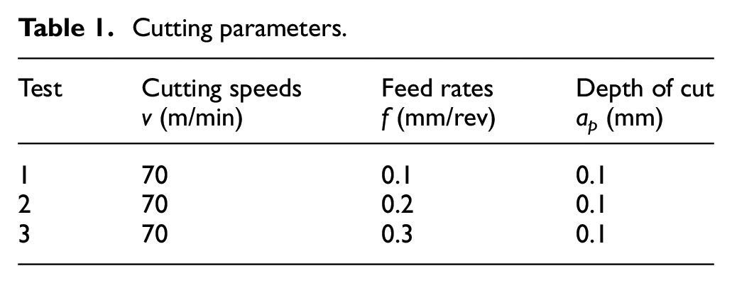
Cutting parameters.
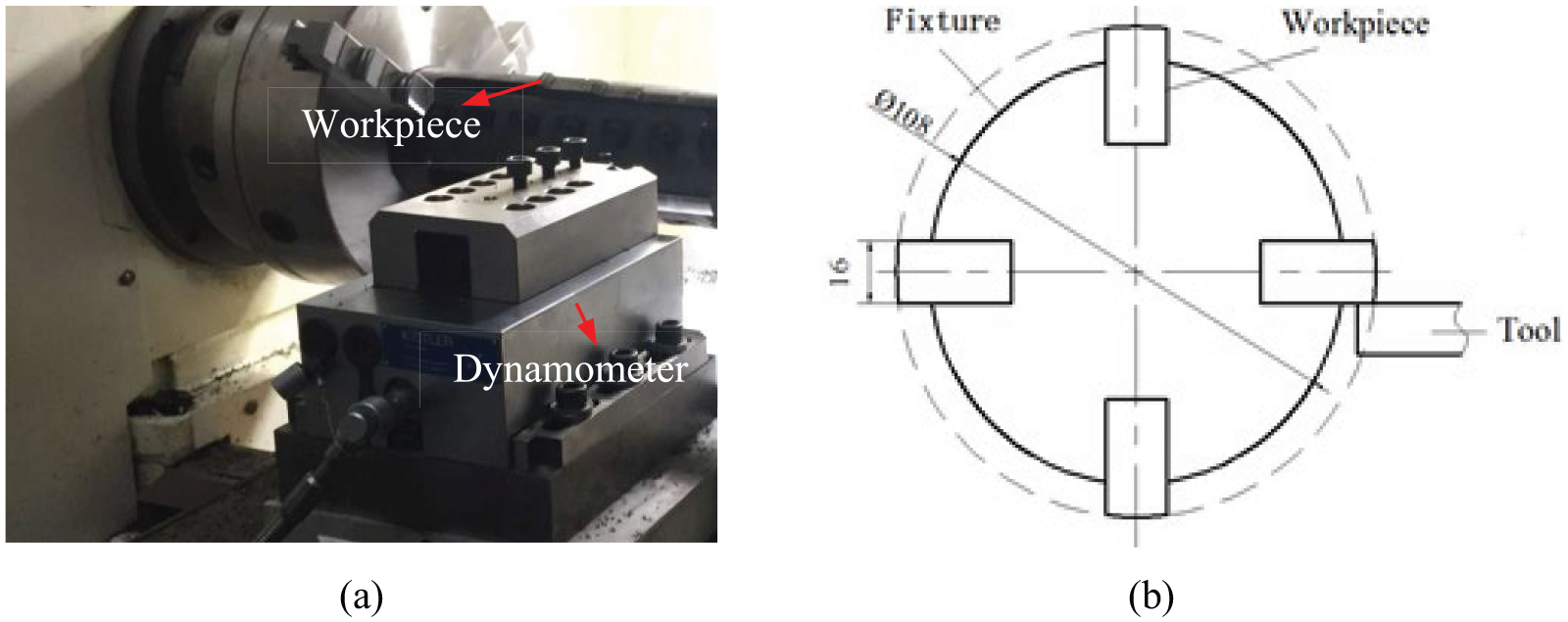
(a) Layout of the experimental apparatus and (b) schematic illustration of workpieces and fixture geometry in intermittent turning experiments.
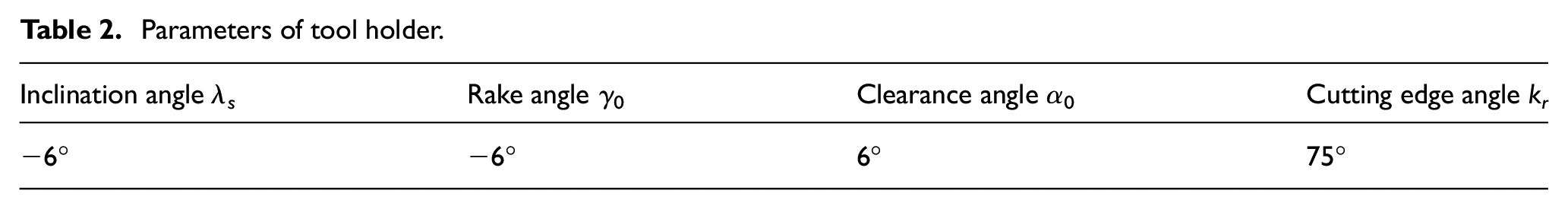
Parameters of tool holder.
Finite element modeling
Metal cutting modeling
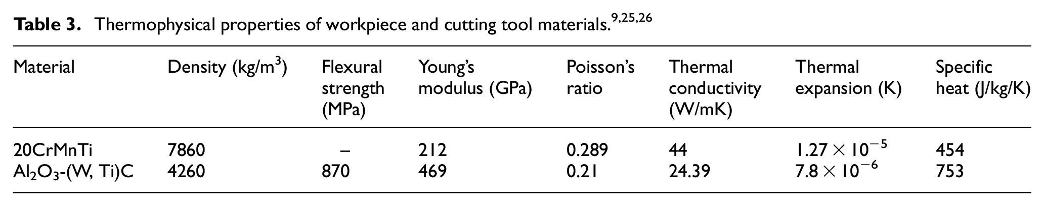
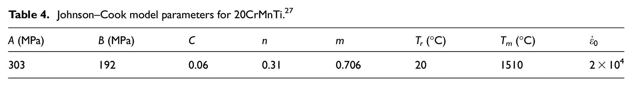
In this article, the FEA of turning processes was made using Abaqus. Both the tool parameters and cutting parameters in FEA corresponded to those used in the experiment. The chip thickness ac was approximately equal to the feed rate f in value. Figure 2 shows the mesh and geometry, assembly of a workpiece, and a cutting tool. The workpiece and cutting tool were discrete, and local meshes that form the chip were refined due to very high stress gradients in the cutting area. Tool–chip friction had also been set up. The boundary conditions are presented in Figure 2. Workpieces kept still and tools moved at the velocity v along machining path. The thermophysical properties of the workpiece and tool material in FEA are shown in Table 3. The Johnson–Cook (J-C) model was used as constitutive equation for steels. The initial temperature of tools and workpieces was set as 20 °C. The parameters of J-C model for 20CrMnTi are given in Table 4.
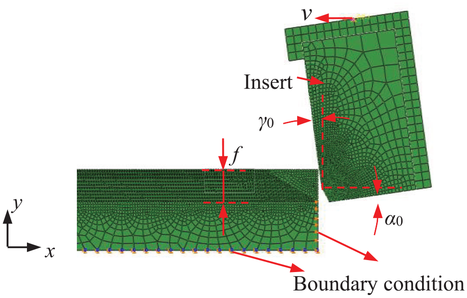
Finite element model of metal cutting.
Johnson–Cook model parameters for 20CrMnTi. 27
Mixed-mode fatigue crack model in intermittent cutting
Figure 3(a) shows a fatigue crack model with a typical geometry and loading of the cutting tool containing a prefabricated crack under the cutting speed of 70 m/min. According to the cutting simulation results, the surface-distributed loads on the cutting tool were loaded at the cutting stages and unloaded at the air cutting stages. The length of prefabricated crack was selected as 0.01 mm as shown in Figure 3(b). The distance between the cutting edge and prefabricated cracks was expressed as d. The effect of different distance d on the fatigue life under different cutting parameters was studied. Crack propagation analyses were conducted using the LEFM.
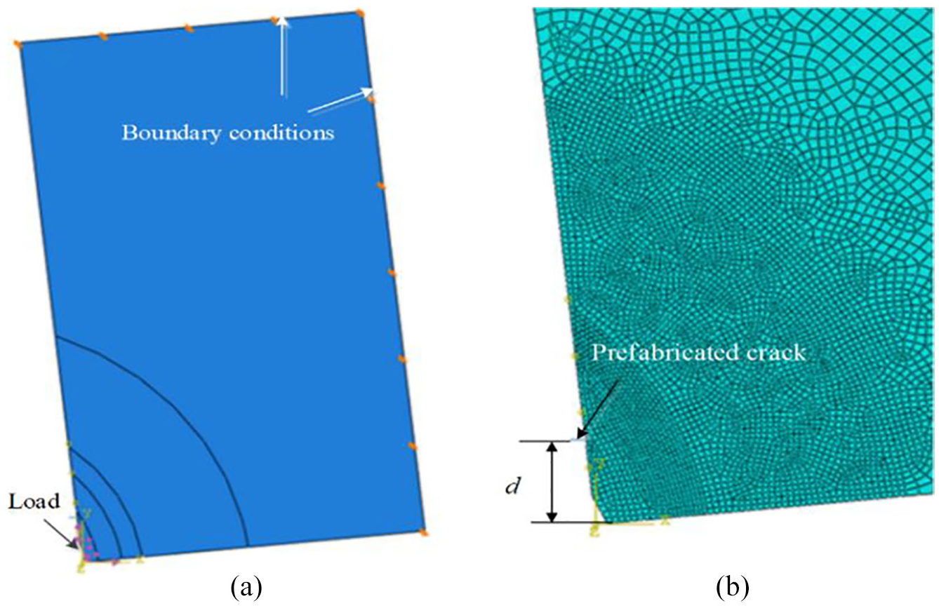
Finite element model of fatigue crack extension: (a) model and (b) mesh.
In Abaqus, 28 the fatigue crack initiation criterion is described as
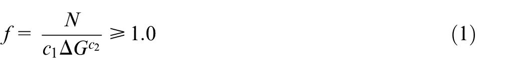
where c1 and c2 are the material constants and N is the cycle number. Here, c1 and c2 are set as 0.5 and −0.1, respectively. The crack growth rate, da/dN, can be calculated based on the relative fracture energy release rate, ΔG. The crack growth follows the following rules advised by Paris29,30
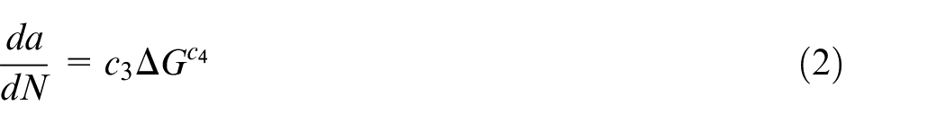
where c3 and c4 are material constants. In this article, material constants c3 and c4 were set as 2.37 × 10²³ and 7.8, respectively, by the comparison of simulation results and the fatigue experiment results of the similar material.31,32 Moreover, the direct cycle time step, including low cycle fatigue, was adopted. For convenience sake, a step size was selected as 0.1.
Results and discussions
Tool failure mode
Figure 4 shows scanning electron microscopy (SEM) images of the rake faces of worn tools in the intermittent cutting tests when the cutting speed was 70 m/min and the feed rate was 0.1–0.3 mm/r. Chipping and fatigue cracks were mainly the tool failure mechanisms. The multi-fatigue cracks generated at the rake face because of the high mechanical impact load, as can be seen in A region in Figure 4(a). As shown in Figure 4(a)–(c), the damaged region was divided into A and B regions by the dotted line. In A region, there were irregular fracture faces mainly under the compression. However, the B region was relatively smooth and flat. Fatigue failure occurred mainly under the condition of cyclic tensile stress on the rake face. And the radius of fan-shaped fracture areas increased with the increasing feed rate. The typical fatigue characteristics, fatigue curve, are observed in B region in Figure 4(c). From the different width between fatigue curves, it can be inferred that the fatigue crack growth rate was unstable. So, under the relatively higher feed rate, fatigue fractures on the rake face were main failure modes when intermittently cutting hardened steels with ceramic tools.
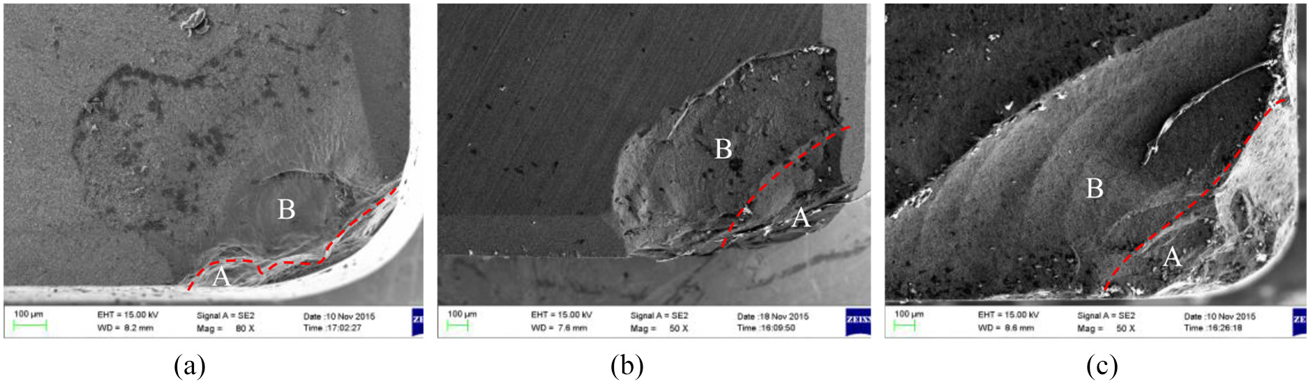
Failure morphology of ceramic insert (ap = 0.1 mm, v = 70 m/min): (a) f = 0.1 mm/r, (b) f = 0.2 mm/r, and (c) f = 0.3 mm/r.
Figure 5 shows SEM images of the worn tool noses in intermittent turning of hardened steel 20CrMnTi at f = 0.1, 0.2, and 0.3 mm/r. The SEM images of the worn tool nose at the different feed rate have the same characteristics. The shape of beach marks which initiated at the tool nose is observed in Figure 5(a), (c), and (e). The stress intensity factor range ΔK was related to the shape of beach marks. 33 The fracture along the flank face was mainly caused by the fatigue crack parallel to the rake face as shown in Figure 5(b), (d), and (f). Furthermore, the damage depth of rake faces increased with the increase in the feed rate significantly. And the fractures of rake faces were main failure modes at f = 0.3 mm/r. The damage to the flank face was strongly affected by the distance from the edge, and there was a maximum value of 0.2 beyond which the fatigue rupture of rake face was the main failure pattern for ceramic tools when intermittently machining hardened steel. Fatigue fractures of tools were caused by expansion and coalescence of cracks.
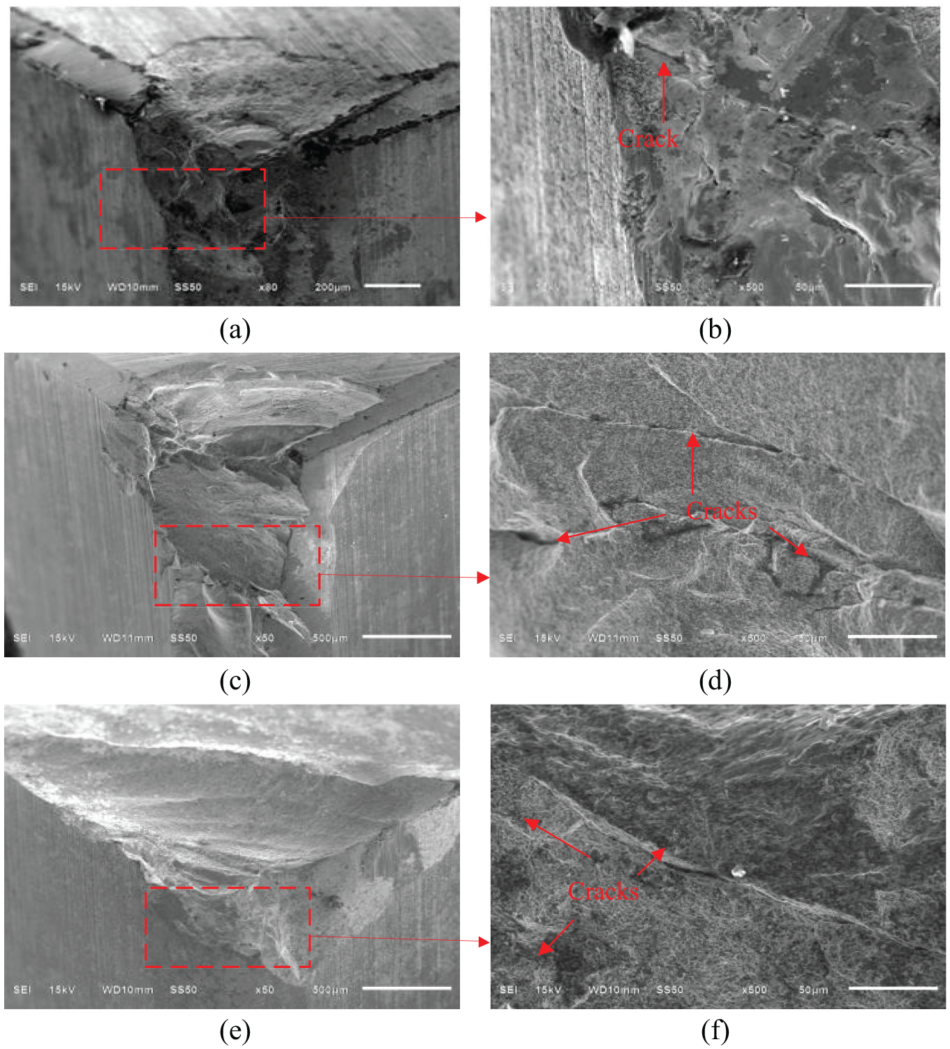
SEM images of ceramic tools in intermittent turning of hardened 20CrMnTi steel (v = 70 m/min, ap = 0.1 mm): (a, b) f = 0.1 mm/r, (c, d) f = 0.2 mm/r, and (e, f) f = 0.3 mm/r.
Tool failure mechanism analysis
Cutting force
Figure 6 shows the experimental cutting forces at v = 70 m/min, ap = 0.1 mm, and f = 0.1 mm/r. When the cutting tools cut into and cut out the workpiece, the impact forces were about 2.5 times of the average cutting forces. Furthermore, the average cutting forces increased with the increase in the feed rate in the intermittent cutting hardened steels. See the literature 34 for a detailed discussion.
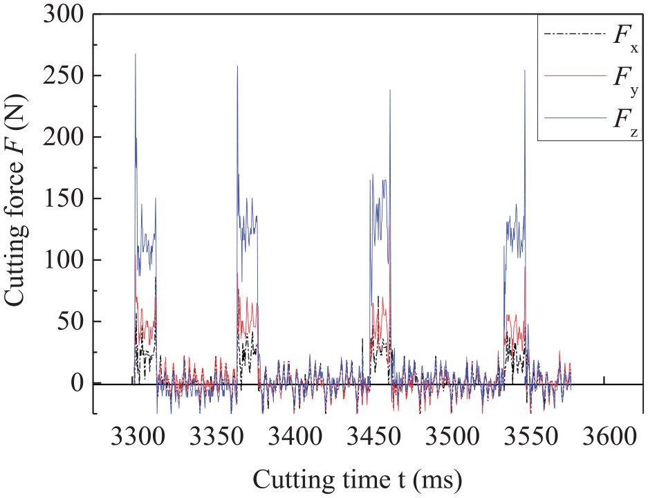
Experimental cutting forces (Fx, Fy, Fz) (v = 70 m/min, ap = 0.1 mm, f = 0.1 mm/r).
Spatial and temporal distribution of cutting stress
Figure 7 illustrates the stress distribution in cutting tools in the cutting process. It can be seen that the maximum principle stress mainly at the location of 2–3 times chip thickness ac (shown in Figure 7(a) by the arrow) was relatively stronger. The contour of Mises stress was shown in Figure 7(b). The stress on the tool–chip interface was complicated in the cutting process. Furthermore, the maximum value of Mises stress was about five times of that of the maximum principle stress. However, ceramics were prone to engender fatigue cracks under the tensile stress. Figure 8 shows the relationship between tangential and normal stresses and y coordinate on the tool–chip interface in the stable cutting stage. The relationship between normal and tangential stresses and y coordinate was replaced by fitting curves. Then, loads could be easily added on fatigue crack models.
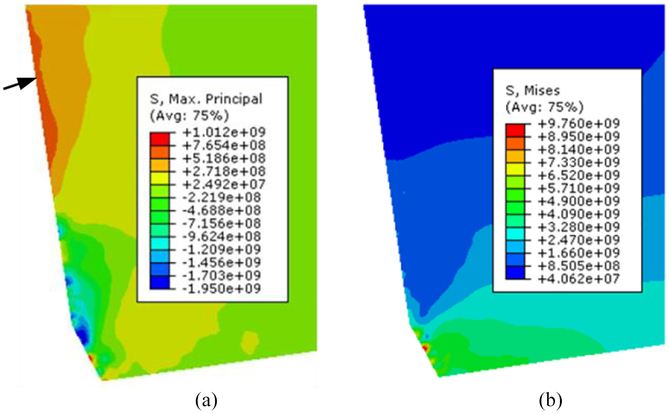
FEA results (ap = 0.1 mm, f = 0.2 mm/r): (a) maximum principle stress and (b) Mises stress.
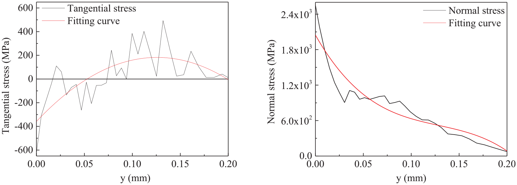
Relationship between (a) tangential and (b) normal stresses and y coordinate (ap = 0.1 mm, f = 0.1 mm/r).
Analysis of fatigue crack propagation
Several snapshots in the process of crack growth for d = 0.25 mm at different number of cycles at f = 0.1 mm/r are shown in Figure 9. When the STATUSXFEM that is an output variable representing status of XFEM element at first unit of prefabricated crack tip was 1, which meant that a crack began to expand, the initiation life Ni of the crack was 5.98 × 10⁵ in fatigue simulation shown in Figure 9(a). The expansion life which was the abbreviation of fatigue life of crack extension of about 0.1 mm was 5.99 × 10⁵ as shown in Figure 9(b). Then, a crack propagated rapidly. And the final crack which caused the cutting tool to fracture along the flank face was shown in Figure 9(c). The simulated fatigue crack path was almost in agreement with the main fracture profile along the flank face in experiments shown in Figure 5(a) at f = 0.1 mm/r. Furthermore, it was seen that the initiation life Ni of fatigue cracks dominates the service life of cutting tools. Then, slowing down the crack initiation rate is the key to improve the tool life.
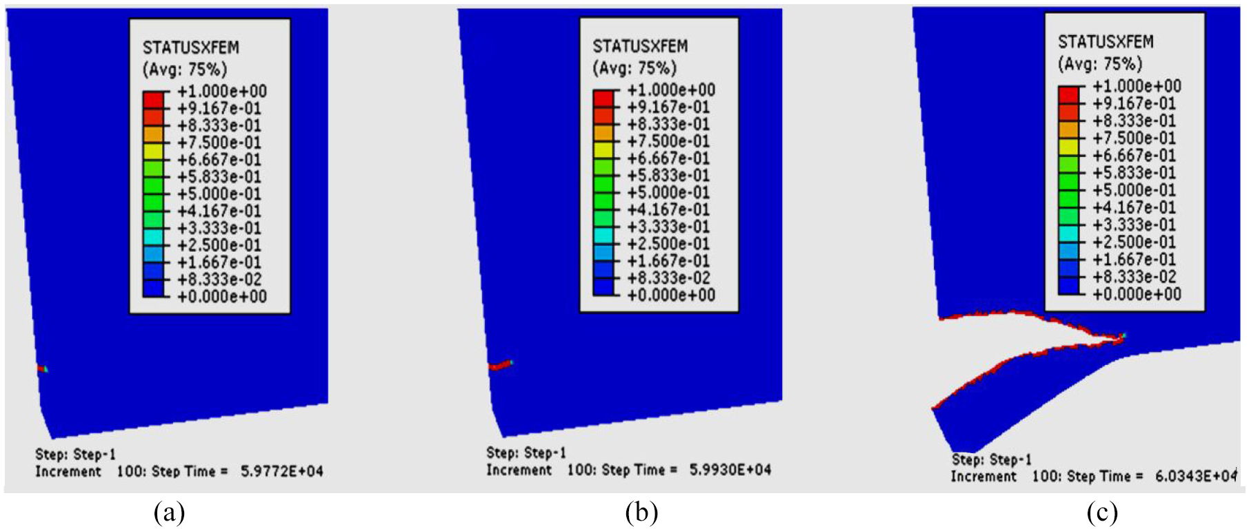
Fatigue crack simulation results for d = 0.25 mm: (a) crack initiation, (b) crack extension of about 0.1 mm, and (c) fracture along flank face.
Figure 10 shows the effect of different crack distance d on the crack initiation life and expansion life. It can be seen that the prefabricated cracks close to the cutting edge had short lifespans under the cyclic loading. In Figure 10(a), the initial life expectancy was 17,600 when the distance d was 0.22 mm. The crack initiation and expansion life did not increase or decrease monotonously with the increase in distance d. Cracks initiated successively at the positions with the distance d of 0.22 mm, 0.35 mm, 0.25 mm, and 0.3 mm away from the cutting edge at f = 0.1 mm/r. Due to the limitations of the current simulation software, one crack can only be prefabricated at a time, and the interaction between cracks cannot be considered. From the fatigue simulation results of limited prefabricated crack, it could be inferred that cracks might easily appear in any position in the range from distance d of 0.22–0.35 mm, and cracks would extend in different ways. As shown in Figure 10(a)–(c), the crack initiation and expansion life followed the similar rule when the feed rate f was 0.1, 0.2, and 0.3 mm/r. It was summed up that the number of cracks (or cracks density) on the rake face increased with the increase in the cutting time (or impact numbers). Furthermore, the radius of fan-type crack growth areas was getting bigger and bigger and the fracture areas also increased with the increase in feed rates. Combined with experimental results, it can be inferred that fatigue fractures of ceramic tools were caused by expansion and coalescence of cracks. These results of numerical analysis were consistent with experiment results shown in Figure 4. On the whole, the fatigue crack was easy to appear on the rake face at the distance d = 1.7f + 0.05 mm or so from the cutting edge. The crack initiation and expansion life were both relatively short. Then, the tool life could be improved by increasing the fatigue strength of the material in this area.
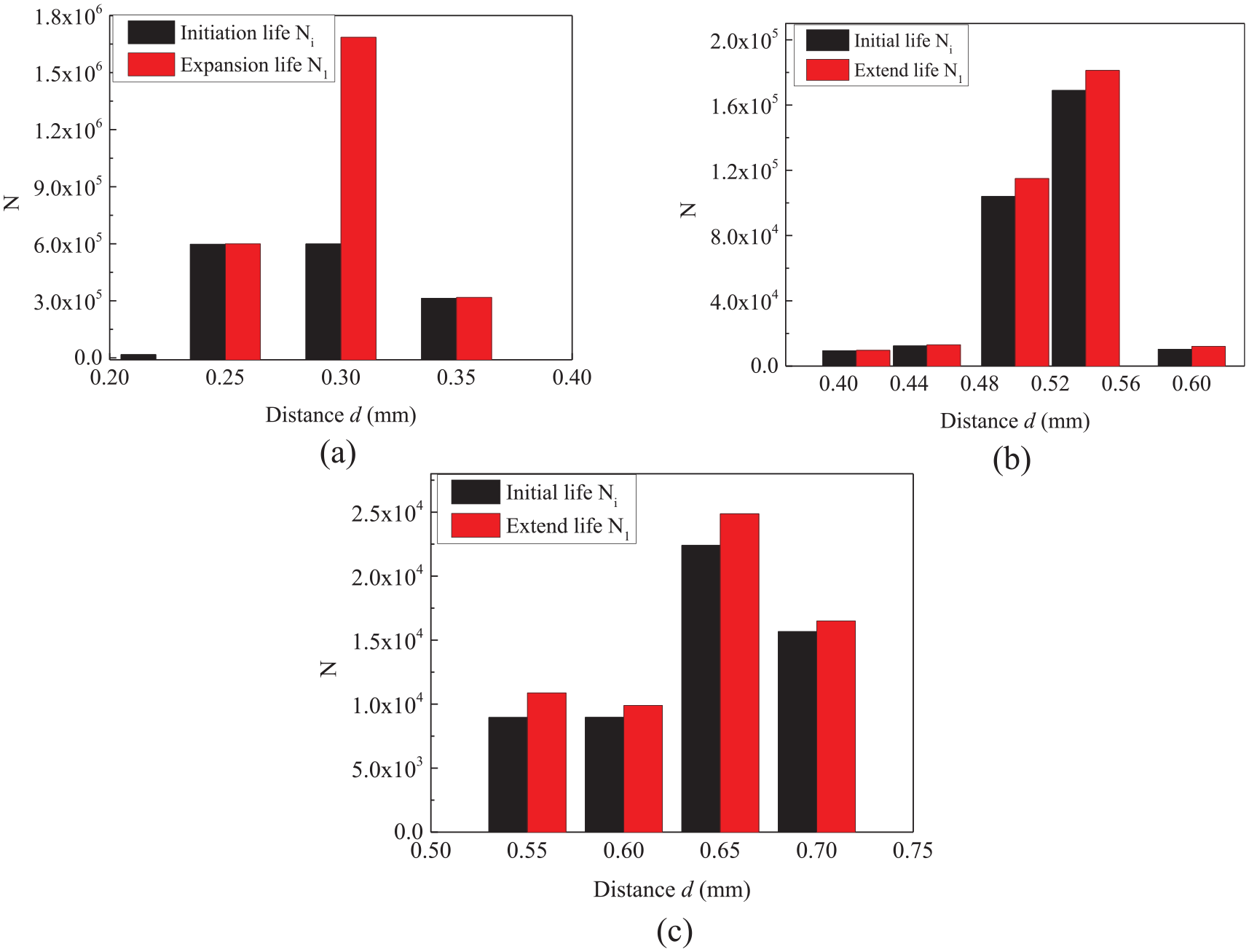
Effect of different distances d on fatigue life: (a) f = 0.1 mm/r, (b) f = 0.2 mm/r, and (c) f = 0.3 mm/r.
For comparison with experimental tool life, the initiation life of the fatigue cracks at the distance d = 1.7f + 0.05 mm or so was chosen as the fatigue life of cutting tools in the cutting simulation based on the previous analysis. In fact, the fluctuation of cutting forces induced by chip formation and the cutting tool enters into and exits from the workpiece during a cutting process cannot be considered enough in the fatigue cracks simulation. Furthermore, considering sensitivity to the stress fluctuation for the brittle material such as ceramic, an impact coefficient k was introduced to amend the fatigue life in simulation. In this article, k was set to 3. Figure 11 shows the comparison between the fatigue life in simulation and the service life in experiments. Because of the discreteness of the fatigue life of ceramics, the FEA calculation results fluctuated around the experimental life of the cutting tool. When the feed rate was greater than or equal to 0.2 mm, the failure mode of the tool was mainly fatigue fracture of the rake face. And the results of fatigue crack propagation simulation well predicted the cutting tool life. On the whole, finite element simulation of fatigue crack propagation presents a useful and implementable tool for revealing the failure mechanism of cutting tool under cycle loads and provides a theoretical basis for research and development of new cutting tools.
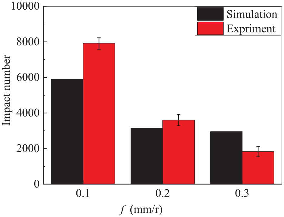
Comparison between the simulated and experimental results.
Conclusion
This article reported the failure modes and mechanisms of ceramic cutting tools in the intermittent cutting of a harden steel (20CrMnTi) under dry condition based on the experiment and simulation results. In particular, a fatigue crack model was established after cutting simulating. Crack propagation analyses at different distances were conducted using the LEFM. The main outcomes of this study were summarized as follows:
In the intermittent cutting of a harden steel, fatigue fracture on the rake face was the primary failure mode at f ≥ 0.2 mm/r, followed by fracture on the flank face. The results showed that the fracture area of flank face reduced with the increase in feed rates, while the fracture area and damage depth of rake face both increased. The typical fatigue characteristics, fatigue curve, are observed in the rake face. The fatigue crack growth rate was unstable. The beach marks initiated at a major source of fatigue. The fracture along the flank face was mainly caused by the fatigue crack parallel to the rake face.
In the fatigue crack simulating, the primary failure mechanism of the rack face was fatigue crack mainly at the location of about 2–3 times chip thickness in the intermittent cutting. The initiation and expansion life of cracks did not increase or decrease monotonously with the increase in distance d. Fatigue fractures of tools were caused by expansion and coalescence of cracks. When the feed rate was greater than or equal to 0.2 mm, the failure mode of the tool was mainly fatigue fracture of the rake face. And the results of fatigue crack propagation simulation well predicted the cutting tool life.
Footnotes
Declaration of conflicting interests
The author(s) declared no potential conflicts of interest with respect to the research, authorship, and/or publication of this article.
Funding
The author(s) disclosed receipt of the following financial support for the research, authorship, and/or publication of this article: This work is sponsored by the National Natural Science Foundation of China (51475273).