
Abstract
A numerical model for studying the time-dependent tribological performance of the floating valve-plate pair in axial piston pump is proposed. The lubrication analysis and the dynamics of the floating valve plate are taken into consideration. An additional source term is adopted into time-dependent Reynolds equation so that the model to analyze the auxiliary balance effects is set up. The boundary pressure of the kidney ports is dynamically coupled with the flow rate towards the loading. It is found that all the performance parameters fluctuate periodically and the valve-plate interface tilt has a vital impact on the tribological performances. The results obtained by the proposed model are highly detailed, and help to improve the understanding of floating valve-plate pair.
Keywords
Introduction
As an important product to transmit mechanical energy into hydraulic energy, axial piston pump is widely used in multiple industrial fields including aerospace and engineering machinery.1,2 The valve-plate pair including a valve plate and a cylinder block is one of the three key tribological pairs in an axial piston pump. In normal operation, the cylinder block is driven by pump shaft. Each piston bore inside the cylinder block alternately connects to high pressure circuit and low pressure circuit via the corresponding kidney ports of valve plate.
There are two design solutions on the valve-plate pair: fixed valve plate or floating valve plate. For a fixed valve-plate pair, the valve plate is fixed in all the directions or machined on the housing. The lubricating interface is generated from the movement of the cylinder block. For a floating valve-plate pair, the valve plate is only fixed along to the rotational direction and moves freely to produce a lubricating interface, while the cylinder block is fixed in all directions to pump shaft.
Experimental research focusing on the fixed valve-plate pair has been carried out by Kim,3,4 Bergada et al. 5 and Wegner et al. 6 All of them were focused on the measurement of gap height. Due to the difference of geometry and operating conditions, the gap heights were measured between 0 and 100 microns. In addition, more experimental investigations have been done by Olems, 7 Jouini and Ivantysynova, 8 and Zecchi. 9 Their focuses were to measure the temperature distribution inside the fixed valve-plate pairs based on the close relationship between the temperature prediction and the tribological prediction. With the rapid development of laser technology, laser surface texturing (LST) is applied to the fixed valve-plate pair. Zhang et al. 10 experimentally investigated the effects of LST by measuring the mechanical and volume efficiencies of high-speed EHA pump and analyzed the wear mechanism based on comprehensive microscope images.
In early models, most investigations were focused on the global performance of a fixed valve-plate pair.11–14 These models were developed to predict the overall leakage, friction torque and average gap height by accounting for more different operating effects. They were simple and cost less computational resources but cannot provide detailed information of a valve-plate pair.
Recently, more CFD-based models came into use with the rapid development of computer technology, which is able to produce more detailed information about the lubricating gap. Wieczorek and Ivantysynova 15 developed a numerical model named “CASPAR” to predict the distribution of gap height by solving for the floating cylinder block position relative to the fixed valve plate. The force balance between the external loads on the cylinder block and the lubricating support forces was achieved at each computational step. Based on CASPAR, Deeken, 16 Huang and Ivantysynova, 17 Jouini and Ivantysynova 8 and Zecchi 9 accounted for more multi-physics phenomena like elasto-hydrodynamic effect and thermal-elasto-hydrodynamic effect to try to predict the tribological conditions more accurately. Han et al. 18 proposed a time-dependent partial lubrication model of the contact surfaces asperity curvature to predict the gap height distribution in a fixed valve-plate pair. Jiang and Yan 19 developed an integrated model to predict the wear distribution within the cylinder block/valve plate interface at steady state.
Previous literature only focused on the fixed valve-plate pair. The floating valve-plate pair has different surface structures compared to the fixed one. Richardson et al.20–22 launched three investigations on floating valve-plate pair. In the first paper, the authors introduced a study on the measurement of gap height and the calculation model on film pressure distribution. The measured gap height results were used in the calculation model. Later, the authors analytically and experimentally investigated the motion of a floating valve plate under various operating conditions by developing a time-dependent model where the auxiliary balance structure was simplified as equivalent spring and dashpot system. The stiffness and the damping of the balance pistons were determined through a batch of impact and frequency response tests. Additionally, the authors updated the lubrication model accounting for film cavitation effect and thermal effect to study the surface modifications with four- and eight-pocket designs on floating valve plate. All the above models didn’t simulate the impact of time-dependent pressure change and boundary conditions in the lubricating interface between floating valve plate and fixed cylinder block.
A coupled numerical model to study the time-dependent tribological performances of the floating valve-plate pair is proposed in this paper. The time-dependent boundaries, which means the connections among the kidney ports, piston bores and auxiliary balance chambers changing with rotation, is handled by modifying the time-dependent Reynold equation and its boundary conditions. The representative dynamic details with regard to a floating valve-plate pair are studied, including interface shape, friction torque, cavitation area, etc. The detailed tribological characteristics of a floating valve-plate pair can be found based on the proposed model, which is helpful to evaluate the tribological performances without time-consuming and high cost tests.
Mathematical model
Physical process
In an axial piston pump, multiple (nine in general) pistons are each supported on the swash plate via the slippers while rotating in the circumferential direction with the cylinder block, thereby resulting in reciprocation with respect to the corresponding bores, as shown in Figure 1.

Schematic of a floating valve-plate pump.
A floating valve-plate pair is composed of a floating valve plate and a fixed cylinder block, which is illustrated in Figure 2(a). When the pump works, each piston inside the cylinder block will alternately perform a reciprocation process. The piston discharges high pressure oil into the loading circuit and sucks the low pressure oil from the boosting circuit. There are two kidney ports and two orifices on the floating valve plate. One kidney port is connected to the loading circuit and the other one is connected to the boosting circuit. Each of the two orifices is connected to the auxiliary balance structure including a small piston and a chamber, which buffers the pressure shock in the phase where the piston moves between the two kidney ports.

Dynamic boundary on floating valve-plate pair: (a) the structure of the cylinder block and valve plate, (b) the faces of the cylinder block an valve plate, (c) the position where five pistons are at high pressure, and (d) the position where four pistons are at high pressure.
The situation of how the pistons connect to the kidney ports or the auxiliary balance chambers is periodically changing as the cylinder block rotates. This feature is referred to as a time-dependent hydraulic boundary. It is different from the fixed valve-plate pair that the connecting process to auxiliary balance chamber results in the complexity of time-dependent hydraulic boundary conditions. In the situation illustrated in Figure 2(c), 5 pistons are connected with the loading circuit, and the other 4 pistons are connected with the boosting circuit. As the cylinder block rotates for some degrees, 4 pistons are connected with the loading circuit and 5 pistons are connected with the boosting circuit, which is illustrated in Figure 2(d). Therefore, the time-dependent hydraulic boundary is the prior concern in numerical modeling on the floating valve-plate pair.
Mathematical formula
Modified time-dependent Reynolds equation
The Oxy coordinate plane is established along the face of the valve plate, as shown in Figure 2. The origin, namely O, is at the center, the x-axis points to a buffer orifice, and the y-axis points to the midpoint of the high pressure kidney port. The kinematics of a floating valve plate is described with the outer radius gap at the three positions uniformly distributed in the circumferential direction,
The flow field of lubricating interface determines leakage and pressure distribution (related with the dynamic behavior). The lubrication is governed by the time-dependent Reynolds equation. The auxiliary balance effect is regarded as a source term in the time-dependent Reynold equation which exists only at the orifices.
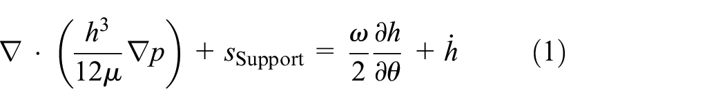

The variable
The boundary conditions on the inner ring and outer ring are defined as Dirichlet boundary,
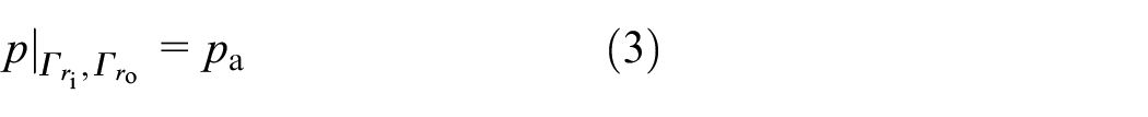
Here, pa is the atmospheric pressure.
The pressure boundary condition on the edge of kidney ports is determined by the characteristics of the loading circuit and the boosting circuit 23 :


Here,
Force equilibrium equation
The forces exerted on the valve plate include those from the lubricating film, auxiliary balance chamber, hydraulics and springs. The inertia of the valve plate and the stiffness of the springs are ignored, since their impacts are very weak compared to the hydraulic force. The generalized force equilibrium equation set is as below:

The cavitation area will be represented with

Here,
The gap height is

Here
The tilt angle of the interface will be represented with
The pressure in the kidney ports
A kidney port is periodically connected to different group of piston bores, the count of which varies with rotation. The oil pressure in kidney ports is governed by
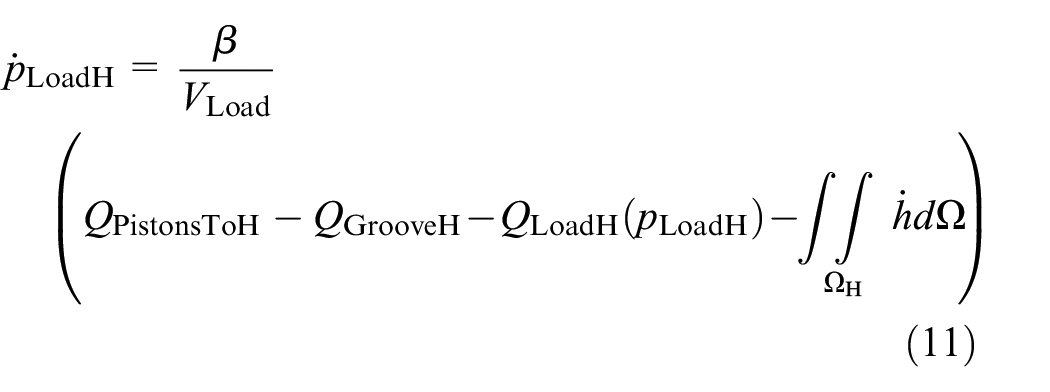

Here
Auxiliary balance effects
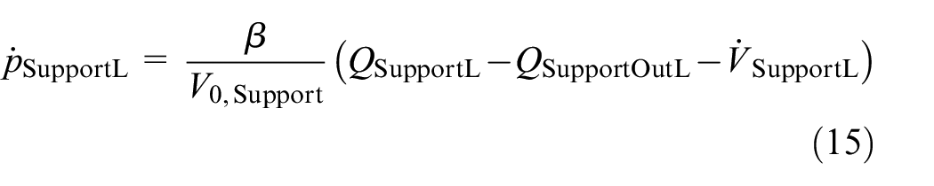
There are two symmetric auxiliary balance chambers, each connected to the face with an orifice, via which the oil in the interface enters the chamber and then escapes to the environment. The chambers make up an essential part in supporting the valve plate, or namely, keeping an adequate closing force.
Take the right chamber (marked with “R”, while the other one marked with “L”) as an example:


Here,
Similarly, with regard to the left chamber,

Performance evaluation
Similar to equations (6) and (7), the flow through the inner ring and the outer ring can be obtained with loop integrals, which constitutes the leakage through the valve-plate pair.

The friction torque is obtained through

Numerical solution
In the numerical solution process, the time is discretized by the finite difference method, and at each time step the finite element method software is used to solve the two-dimensional partial differential equations.
The finite difference on time is performed as

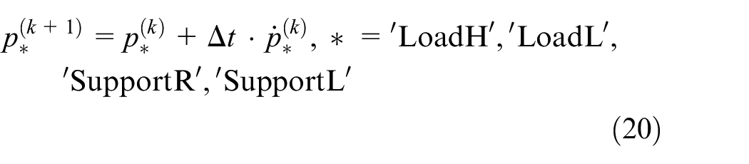
After solving the model at each time step with finite element method software, the model at the next time step is generated with equations (18) and (19), as illustrated in Figure 3.

Flow chart of numerical solution.
Results and discussion
Simulation parameters
The parameters are shown in Table 1. Four cases at the same speed (2500 rpm) are investigated in order to find out the performance change with different hydraulic pressure (10, 20, 30 and 40 MPa). In each case, the cylinder block with shaft rotates 4 rounds and the pump is assumed to work in steady state.
Parameters in the model.

The problem is solved and compared to the analytical method as below, 24

The 40-MPa case is taken as an example. Figure 4 shows the comparison on radial distribution of lubricating pressure between the results obtained by the proposed method and those obtained by the analytical method. They are in good agreement with the difference less than 1.5%. So the proposed model is convinced and able to provide more detailed information on the tribological characteristics during time-dependent process.
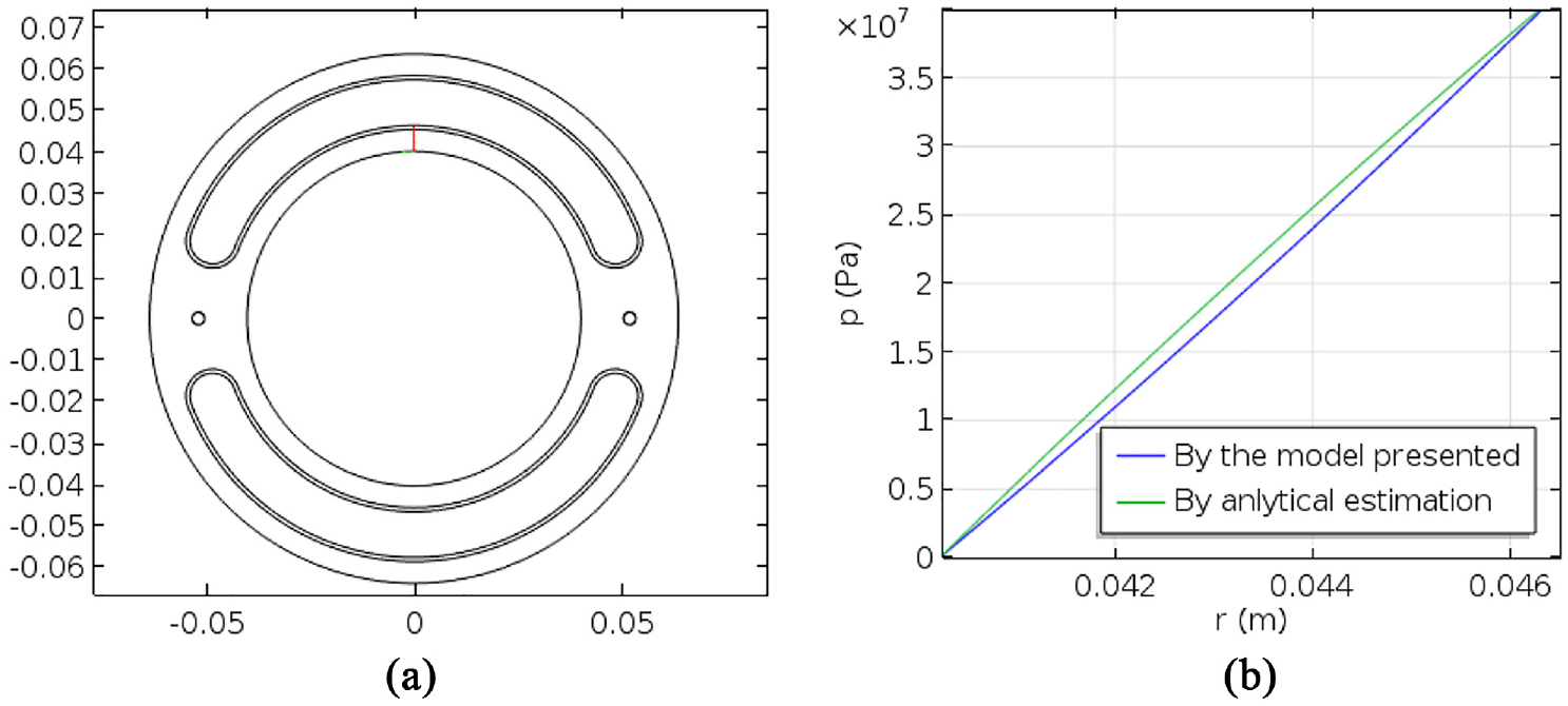
Verification on numerical results: (a) the site for comparison and (b) the comparison of the results by the model presented and by analytical estimation.
Time-dependent behavior in one complete shaft rotation
Thanks to the full consideration of the pressure distribution and a time-dependent analysis, the motion, time-dependent pressure field and fluctuating performance parameters are obtained. Figure 5 illustrates how the parameters fluctuate. In general, the periodicity is obvious and anchored in the circumferential periodical structures: Because 9 pistons are involved, most parameters show the periodicity of 360°/9=40°.

The tribological performances of valve-plate pair: (a) lubricating interface shape, (b) oil pressure inside the right auxiliary chamber, (c) cavitation area, and (d) leakage and friction torque.
Figure 5 (a) indicates the floating characteristics of valve plate, which determines the lubricating interface shape. The height is generally around 5 μm. The interface tilt and the fluctuation of a floating valve plate are not significant. During each 40° there are two peaks and two valleys, or, each 20° is a minor period.
Figure 5(b) plots the pressure fluctuation inside the right auxiliary balance chamber. It is clear that the oil pressure completely depends on the periodic process connecting to each piston, thus with a periodicity of 40°. The high pressure value slightly fluctuates around 40 MPa in half of the cycle.
Figure 5(c) shows the changes of the cavitation area. The cavitation area also varies with a periodicity of 40°. There are three peaks in one cycle. The phenomenon of cavitation has a close relation with the variation of lubricating interface shape, and will be discussed later.
Figure 5(d) shows the performance evaluation of a valve-plate pair including leakage and friction torque. The leakage is significantly disturbed when a piston move across an auxiliary balance chamber (at 0° and 20°). The cavitation area can be temporally large at some particular phases, and meanwhile the reversed leakage takes place. That means the valve plate may suck oil, air or mixture from housing only for a very short duration. It is never reported in the past for the flow meter is unable to respond in such short time. The friction torque has a good synchronous fluctuation with the interface tilt: When the interface tilt is close to a minimum value, the friction torque reaches a peak.
The distributions of lubricating pressure, film cavitation and gap height
Furthermore, the relationship between pressure distribution and interface tilt and the one between film cavitation and interface tilt are studied. Figure 6 gives detailed illustrations for the 40-MPa-condition at every 5° (so that the 8 instances make up a 40° period), with regard to the lubricating pressure field, film cavitation region and gap height distribution.

Field plots for the valve-plate pair under 40 MPa condition.
Generally, it can be found that the lubricating pressure is generally high around the high pressure kidney port and is low elsewhere, and that the film cavitation does not distribute uniformly in the circumferential direction and fluctuates with rotation position. Two phases should be studied carefully, including 0° and 20°, near which one of the pistons switches from one kidney port to the other. Specifically, the piston at right (in Figure 2(c) and (d)) switches from the kidney port of the boosting circuit to that of the loading circuit near 0°, and the piston at left switches from that of the loading circuit to the one of the boosting circuit near 20°. Similar to the phenomenon that the performance is strongly disturbed near the two phases, the lubricating pressure field is disturbed at the same phases. At the phase of 20°, the pressure in the left auxiliary balance chamber undergoes a violent change. A similar violent change takes place at the angle of 0° for the pressure in the right auxiliary balance chamber, accompanied with cavitation occurring in a large area. Therefore, the valve plate is especially vulnerable at the two phases, as the rupture of the oil film leads to erosion. After the two abovementioned instable phases, the cavitation area decrease at 5° and 25°, which may lead to erosion.
The distribution of pressure and cavitation depends on the gap height distribution, which shows a biased tilt due to the structural asymmetry. It is uncovered that the direction of interface tilt is perpendicular to the moment formed by the high pressure side and the low pressure side. The lubricating interface shape is convergent at the high pressure side and divergent at the low pressure side. As the tribological pair rotates, the lubricating film flows into convergent gap so that the hydrodynamic support will be produced. It is referred to as the hydrodynamic effect. And the moment formed by the hydrodynamic effect can support the valve plate against the moment of the face pressure distribution. Meanwhile, the diverged gap may further lead to film cavitation if the two auxiliary balance chambers are not both filled with high pressure oil to push the valve plate. It is enlightening for avoiding the cavitation damage during prototype development if the film cavitation process is well illustrated.
Comparison of the tribological performance under different loading conditions
In engineering practices, the higher hydraulic pressure is more likely to result in the risk of wear or failure. Therefore, the comparison among the results at pressure of 10 MPa, 20 MPa, 30 MPa and 40 MPa, respectively, is performed and exhibited in Figure 7.
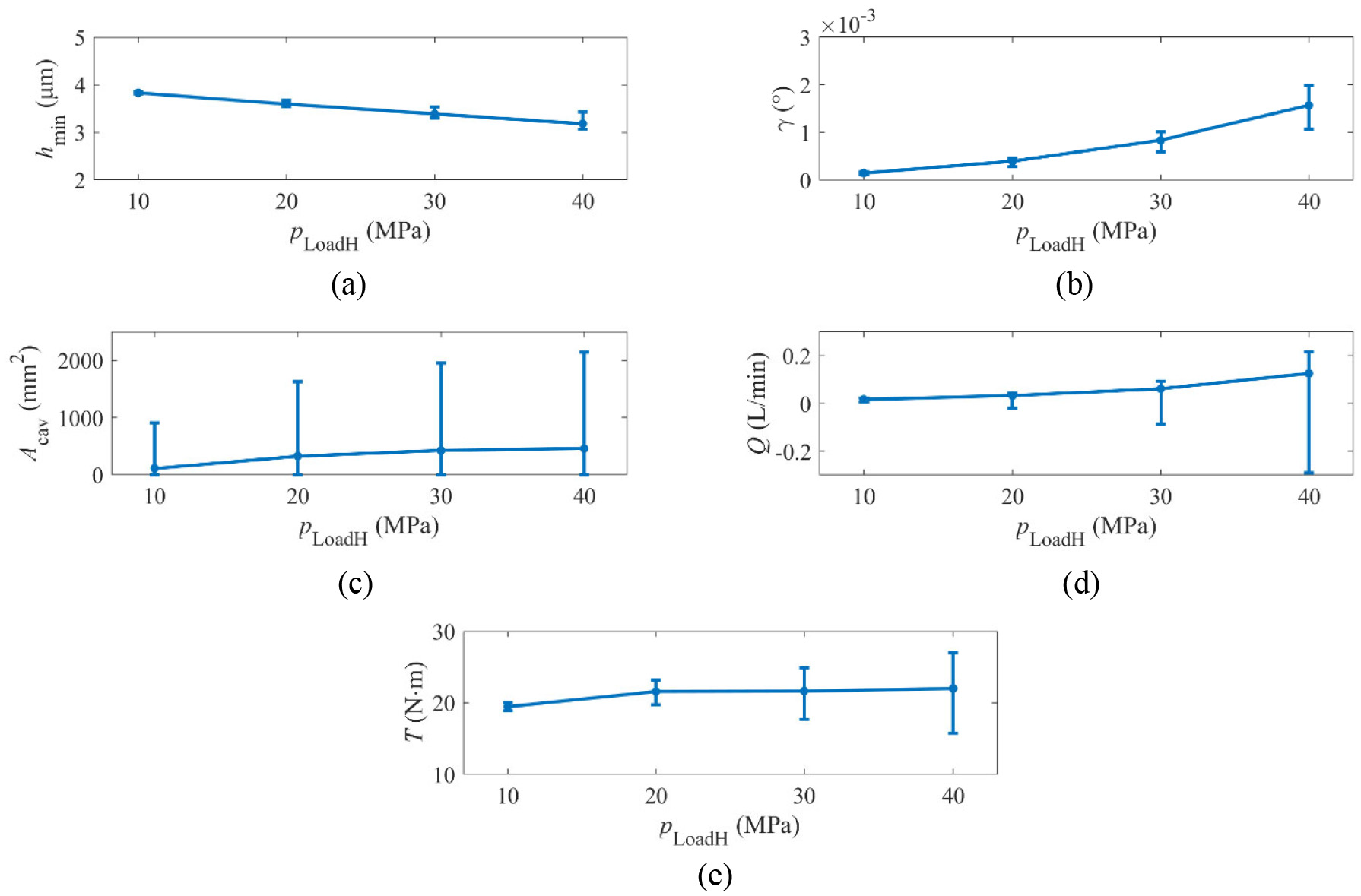
Tribological performance curves of the valve-plate pair under different operating conditions: (a) minimum height, (b) interface tilt, (c) cavitation area, (d) leakage, and (e) friction torque.
The minimum height decreases with the increase of hydraulic pressure. This is caused by the stronger interface tilt intendancy brought by the greater pressure. The greater interface tilt leads to the greater risk of contact, and the change of pressure plays further impact to other behaviors.
As abovementioned, the major cause to film cavitation is the divergence gap along to the circumferential direction. Therefore, the higher hydraulic pressure induces greater interface tilt, and thus more severe cavitation. Meanwhile, the instant reversed leakage also becomes more severe.
The hydraulic pressure shows significant impacts on leakage: Firstly, since the hydraulic pressure makes the pressure difference between two sides of lubricating interface, the leakage linearly depends on hydraulic pressure. Secondly, the interface tilt becomes larger as the hydraulic pressure increases. And the larger interface tilt indicates the bigger gap at one side where the leakage is extremely high (it should be noted that the leakage keeps a cubic power function of gap height in parallel interface assumption).
Concerning the friction torque, the impact of hydraulic pressure on the average value is relatively small, while the fluctuation of friction torque is increased obviously with the hydraulic pressure rising.
Conclusions
The present work proposed a numerical model to predict the dynamic behavior of floating valve-plate pair. The model simulates the tribological process based on a modified time-dependent Reynold equation, the complicated time-dependent hydraulic boundaries for which are coupled the combination of the fixed boundaries (using Dirichlet boundary condition with pressure values coupled with flow rate), the large groove depths and the source terms (representing the flow from other chambers and depending on the local pressure). The dynamics and the lubrication of floating valve-plate pair are coupled and solved under different operating conditions. The following conclusions are reached:
The proposed model obtains the time-dependent results including the distribution details of floating valve plate and the tribological performances (pressure field, film cavitation, flow, and etc.). The model is capable of revealing the complex changing progress of the pressure distribution around the auxiliary balance structures and the film cavitation inside lubricating interface, which is superior to the analytical method.
All the tribological behaviors fluctuate periodically, which are anchored in the circumferentially periodic structure. The performance is strongly related to the gap height distribution. The interface tilt plays an essential impact on the working situation of the floating valve-plate pair. Instant reversed leakage induced by film cavitation is predicted as a new phenomenon.
The pressure field and the film cavitation position are directly related to the interface shape. The floating status of valve plate leads to hydrodynamic effect which produces a moment perpendicular to the interface tilt to resist the pressure difference, and that is the reason why the minimum gap height shows up near to the left auxiliary balance chamber. It is revealed that the tilting of the valve plate is a major cause to film cavitation so that better dynamic characteristics will help to avoid the damage of cavitation. The pressure changes inside the auxiliary balance chambers are the other cause.
An increasing hydraulic pressure leads to a greater interface tilt, and then the valve-plate pair shows generally worse performances, mainly including higher leakage, larger cavitation area, and a greater risk of contact and wear. Therefore, a better resistance to interface tilt is the key to improve the tribological performance.
The results revealed by the proposed model are highly detailed, and thus can provide an instruction for optimal design. The significance of dynamics indicates that the research and diagnosis could be greatly supported through monitoring the motion with acceleration sensor or displacement sensor. The performance and reliability can be enhanced by strengthening the interface tilt resistance and optimizing the pressure fluctuation inside the auxiliary pressure chambers. The method with which the model handles the time-dependent hydraulic boundary is delightful for solving the problems on similar tribological pairs.
Footnotes
Appendix
Handling Editor: James Baldwin
Declaration of conflicting interests
The author(s) declared no potential conflicts of interest with respect to the research, authorship, and/or publication of this article.
Funding
The author(s) disclosed receipt of the following financial support for the research, authorship, and/or publication of this article: This work is supported by the National Natural Science Foundation of China [Grant numbers U1737202 and 51605450.