
Abstract
The leakage of the valve plate pair of the internal curve hydraulic motor significantly affects its volumetric efficiency and machine performance; however, its leakage mechanism is unclear. This paper considers the self-compensating ‘floating’ type of valve plate as the study object, proposes a calculation method for the leakage of the valve plate pair of the internal curve hydraulic motor, and studies the leakage law and oil film characteristics of the valve plate pair. The results show that the rotational speed has less influence on the leakage amount and oil film thickness of the valve plate pair; the inlet pressure has a linear relationship with the leakage amount and oil film thickness; with the increase of the oil temperature the leakage amount of the valve plate pair decreases gradually, and oil film thickness is parabolic shape changes, but the oil film thickness tends to change smoothly in the range of oil temperature 40°C–55°C; the geometric shape of the oil film of the valve plate pair and the distribution of the pressure are cyclic within the periodic angle of the motor, and the pressure of the oil film is radial distribution in the inlet area, and the sealing band pressure is nonlinearly decreasing in the radial direction, the oil film leakage velocity in the motor periodic angle is ‘M’ shaped distribution.
Keywords
Introduction
Internal curve hydraulic motor (multi-acting internal curve radial piston hydraulic motor) is widely used in the fields of shipping, construction, and the chemical industry, because of their good low-speed stability and large output torque.1–3 The use of a ‘floating’ type valve plate with a self-compensating mechanism in the internal curve hydraulic motor (ICHM) not only creates an ideal macro-stable oil film (dynamic balanced oil film) but also actively compensates for the clearance in the valve plate pair (the friction pair consisting of the end face of the cylinder block and the end face of the valve plate) to ensure the sealing and lubricating properties of the valve plate pair (VPP). However, owing to the clearance in the VPP and the relative motion of the sliding surface, leakage is unavoidable,4–6 and the leakage of the VPP is the main cause. When the leakage of the VPP is too large, it reduces the sealing of the VPP and the volumetric efficiency of the motor, 7 which affects its performance. When the leakage is too small, the lubrication of the VPP is not good, which leads to the wear of the valve plate, and when it is serious, it will even lead to the phenomenon of ‘burning the valve plate’.8,9 The leakage of the VPP is mainly determined by the characteristics of the oil film, and without considering the properties of the oil fluid, the thickness, geometry, and pressure distribution of the oil film are the main factors causing leakage in the VPP. However, because the valve plate is the core functional element of the ICHM, it is difficult to study the leakage and oil film characteristics directly.10,11 Therefore, this study proposes a method for calculating the leakage amount of the VPP to study the leakage mechanism of the VPP of the ICHM.
The principles of internal leakage in hydraulic pumps and motors are similar. Therefore, the study method for the internal leakage of the ICHM can draw on the research results of the internal leakage of axial piston pumps. In other papers, some scholars have established a numerical model of axial piston pumps, determined their dynamic characteristic model, and derived a formula for the instantaneous pressure in the piston chamber and the instantaneous leakage equation of the VPP.12,13 However, the main causes of leakage in axial piston pumps have not been clarified. In addition, some studies have explored the leakage factors of axial piston pumps and pointed out that the main channels of leakage include the valve plate, piston, and sliding pairs of the pump. They established a mathematical model of the internal leakage of axial piston pumps,14,15 which is of great significance for studying the internal leakage of ICHMs. A method based on the joint calculation of computational fluid dynamics (CFD) numerical calculation and mathematical model of internal leakage of an ICHM was proposed by Ma et al. to calculate the internal leakage of the ICHM and analyze the degree of effect of different factors on the leakage. 16 Li et al. studied the flow field characteristics of the ICHM by using the CFD software and analyzed the effects of the thickness of the film of the VPP, the inlet pressure, the motor rotational speed, and the temperature of the oil fluid on the leakage amount. 17
Fixed and ‘floating’ valve plates are similar in structure, therefore, the calculation theory of a ‘floating’ valve plate is based on the calculation theory of the fixed valve plate. The fundamental problem of leakage of the VPP of the ICHM lies in the change in the oil film characteristics. For axial piston pumps, scholars have studied the leakage of the internal and outer sealing bands of the valve plate under different pressures and performed theoretical calculations; however, they did not explore the root cause of the leakage problem.18,19 Chen et al. investigated the effect of the axial piston pump valve plate structure on the oil film pattern and lubrication performance and analyzed the relationship between the depth of the ‘V’ shaped structure and the thickness of the oil film of the VPP and its effect on the leakage. 20 Haidak et al. established a thermoelastic flow model of axial piston pumps, analyzed the characteristics of the oil film of the VPP under different conditions, and proposed a method for reducing the leakage of the VPP. 21 Wu took the axial piston motor as a research object and analyzed the flow field of the damping grooves of the VPP with different forms. A new type of valve plate with damping grooves was proposed, and the internal leakage and cavitation phenomena of the VPP under different structural parameters were revealed. 22 Kumar and Mandal studied the VPP of a radial piston pump, optimized the geometrical design of the valve plate end face, calculated the flow area of the mating window, and analyzed the effect of the interaction of the VPP end face on the flow characteristics of the oil film. 23 However, no detailed analysis of the oil film characteristics of the VPP has been conducted.
In summary, domestic and foreign scholars have conducted numerous theoretical analyses and experimental studies on the internal leakage and noise of axial piston motors and pumps, oil film thickness and pressure distribution of the VPP, leakage of the VPP, and the force analysis of the valve plate. However, there are relatively few studies on the oil film characteristics of the self-compensating ‘floating’ valve plate of the ICHM, and the leakage mechanism of the VPP of the hydraulic motor is not yet clear. Therefore, this study proposes a method for calculating the leakage amount of the VPP, to analyze the leakage law of the VPP under different working conditions, to study the variation law of the oil film thickness of the VPP with the working conditions of the motor, and to explore the geometric changes in the oil film, pressure distribution, and leakage amount. Through a study of the leakage mechanism of the VPP of the ICHM, this paper provides theoretical guidance for the optimal design of the structural parameters of the valve plate and the improvement of the suitability of the pressing force of the VPP.
Experimentation
In this paper, the internal leakage of an ICHM was tested using a test bench, which provided data support for calculating and analyzing the leakage of the VPP. The hydraulic principle of the test bench is shown in Figure 1, which is mainly composed of the driving part, load pump, test motor, control system, and data-acquisition system. The hydraulic pump was driven by an electric motor to provide a stable oil source for the test motor, and the pressure of the load pump was generated by a closed circuit, which simulated the actual working conditions of the test motor by adjusting the flow and pressure in the load circuit. The control system collected and recorded the test data using various sensors, whereas the host computer monitored and recorded the internal leakage, pressure, temperature, and other information of the test motor in real-time.

Design schematic diagram of hydraulic system.
This test controls the rotational speed of the test motor by adjusting the speed control valve in the charge circuit of the load pump and limits the working pressure of the test motor by controlling the pressure of the circuit through the proportional relief valve to test the internal leakage of the motor under different rotational speeds, working pressures, and oil temperatures. The test equipment includes ZH07 torque speed sensor produced by Beijing AVIC Science and Electricity, PT5401 pressure sensor produced by IFM, GF6F1P1 gear flowmeter produced by HUZHOU Instrumentation, CRM-HA50-50 ICHM produced by Stauffer Hydraulics,HL-A4VS071E02 variable displacement pump and CBF-F410 gear pump produced by Ningbo Hengli. The test bench is shown in Figure 2.
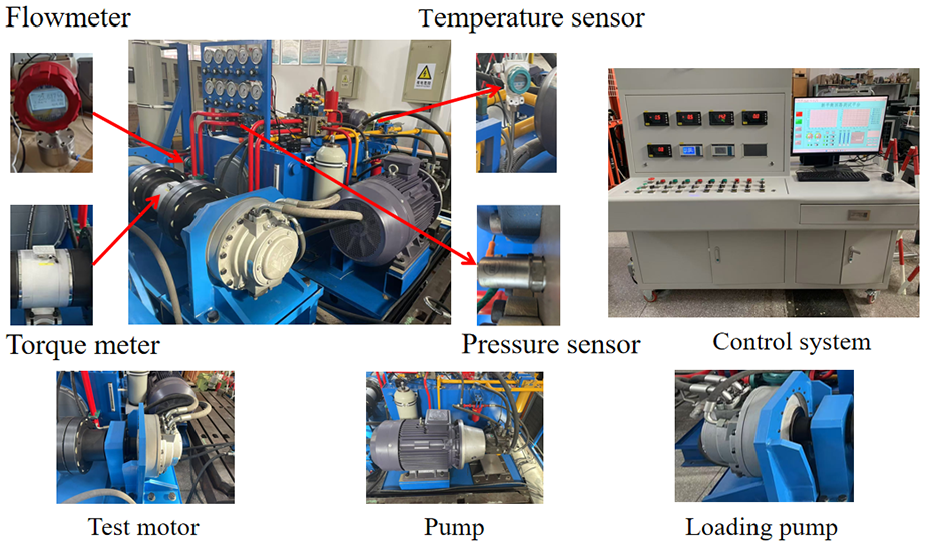
Internal leakage test bench for ICHM.
The experimental process was as follows: first, before the test started, an internal leakage test item list for ICHM at four different rotational speeds, four different oil temperatures, and six different inlet pressures was prepared; then, the test was started according to the requirements of the working conditions, and the amount of internal leakage of the motor as well as other parameters under different working conditions were recorded after the test bench had been running stably for 5 min; finally, through several repetitions of the test, the authenticity and reliability of the collected data are ensured to meet the requirement of the amount of data for calculating the leakage of the VPP.
Numerical modeling
Structural modeling of ICHM and valve plate
As shown in Figure 3, the main components of the ICHM are the cylinder block, valve plate, piston, and roller. The oil inlet hole of the valve plate and cylinder block bore of the rotor form a mating window, which not only distributes the oil flow direction but also switches between the high-pressure and low-pressure oils. When high-pressure oil enters the piston chamber through the flow channel in the piston, the hydraulic pressure acting on the piston pushes the 16 piston groups (consisting of the piston and roller) to perform an orderly reciprocating motion along the stator ring, and there are 10 sections of action curves with the same geometry and curvature uniformly distributed on the stator ring. When the roller and stator tracks are squeezed against each other, the stator track under the action of hydraulic pressure causes the piston groups to produce radial and tangential forces, which accelerate the discharge of oil from the piston chamber, and the cylinder block rotates under the action of torque such that the ICHM outputs continuous speed and stable torque.

Schematic diagram of the structure of the ICHM.
The ICHM adopted a self-compensating structure with a ‘floating’ valve plate, as shown in Figure 4. The 20 balance chambers were evenly distributed on the valve plate, and the flow channel ports of the balance chambers were connected to the bore of the cylinder block. The pressure in the piston chamber is the same as the pressure change in the balance chamber, so that the pressing force generated in the balance chamber and the separation force of the VPP are always kept in a state of balance, and the valve plate and end face of the cylinder block are kept in parallel and are always in a state of ‘floating’, thus effectively avoiding fast changes in the working pressure of the ICHM, resulting in insufficient or excessive pressing force of the VPP. Furthermore, the structure ensures not only that the VPP is in a good lubrication and sealing state, but also stabilizes the thickness of the oil film of the VPP and reduces the leakage of the VPP. Therefore, optimizing the structural parameters of the self-compensating ‘floating’ valve plate is of great significance in improving the performance of the VPP of the ICHM.
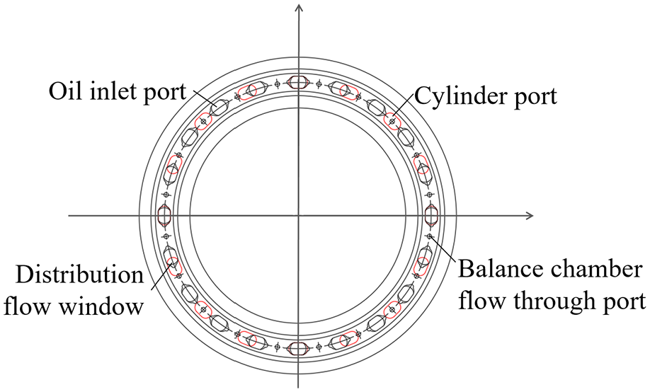
Schematic diagram of the valve plate structure.
Mathematical modeling of leakage in an internal curved hydraulic motor
Mathematical modeling of internal leakage in ICHM
The internal leakage of the ICHM is due to the working pressure, rotational speed, oil temperature, and other factors under the joint action of the friction pair clearance leakage generated. The leakage of the VPP was the main source of leakage in the ICHM. The leakage of the piston pair accounts for a relatively small amount, whereas the leakage of the roller pair is very small and negligible. The Ma team at Lanzhou University of Technology has conducted relevant research on this issue. 16 Because this study focused on the leakage of the VPP, the calculation of the internal leakage of the ICHM is not repeated, and the formula for the internal leakage of the ICHM was as follows:

Where Q is the internal leakage of the ICHM.
Mathematical modeling of leakage in VPP
It is assumed that the flow in the oil film of the VPP is laminar and that the pressure in the vertical film direction remains constant. The leakage of the VPP was mainly caused by the flow of oil from the inner and outer sealing bands of the valve plate, and the sealing band leakage was affected by the pressure in the piston chamber and the range of the pressure wrap angle. In this paper, a 16-piston 10-acting ICHM is used as the research model. When the motor is running, the piston chamber pressure and pressure wrap angle vary on an action surface, and its calculation method has been detailed in other papers, piston chamber pressure, and pressure wrap angle vary on an action surface, and its calculation method has been detailed in other papers; however, this paper will not repeat it. The hydraulic component clearance flow characteristics can be derived from the ring seal clearance leakage formula, the leakage flow formula of the VPP of the ICHM is as follows:
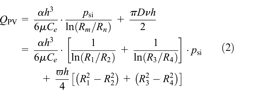
Where
Mathematical modeling of piston pair leakage
It is usually assumed that the piston pair film is laminar and incompressible, and when the ICHM rotates, the piston performs a radial reciprocating motion with the stator ring, which leads to a pressure change in the piston chamber, thus causing piston pair leakage. In general, the radial clearance between the piston and cylinder block is set to 0.01 mm. Because the pressure field generated by the flow of the piston oil film has a self-positioning effect on the piston, the leakage caused by the eccentricity of the piston in the piston chamber was not considered in this paper. According to the piston clearance leakage formula, the calculation formula for piston pair leakage can be deduced as:

Where
Mathematical modeling of oil film thickness in VPP substrate
The internal leakage of the ICHM can be directly obtained through testing. Ma et al. 16 from Lanzhou University of Technology used the ANOVA method to analyze the test results of the internal leakage of the ICHM, thus verifying the correctness and reliability of the motor leakage test results. When the working condition of the motor is certain, the leakage amount of the piston pair remains constant, which can be calculated using the formula for the leakage amount of the piston pair. Therefore, the leakage amount of the VPP was calculated using the following formula:

Where
That is, the joint equations (2)–(4) can get the oil film thickness calculation formula of the VPP as follows:

Where h is the thickness of the oil film of the VPP. α is the pressure wrap angle.
The main calculation parameters of the leakage of the VPP are shown in Tables 1 and 2.
The main calculating parameters.

Viscosity of LHM 46 # hydraulic oil at different temperatures.

Mathematical modeling of the geometrical shapeof the oil film in the VPP
The valve plate structure of the ICHM was symmetric in the right-angle coordinate system along the x-axes and y-axes. As shown in Figure 5, the area of the oil film on the valve plate can be simplified and calculated in the xoy quadrant of the coordinate system. As the cylinder block rotates, the projected area formed by the cylinder block bore and valve plate bore can be expressed as follows:


Schematic diagram of the calculation of the oil film area of the valve plate.
The projected area of the oil film is expressed as follows:
Where
Therefore, the oil film area

Where A is the end face area of the valve plate.
The projection area
Mathematical modeling of oil film pressure distribution in the valve plate substrate
In general, the pressure distribution law of an oil film can be formulated using the Reynolds equation,26–28 which is solved by setting the boundary conditions of the equation. However, because it is very difficult to solve the Reynolds equation directly mathematically, the difficulty of solving it is reduced using numerical methods for the finite element method (FEM). The following assumptions were made when deriving the Reynolds equation for the oil film:
(1) The oil is a Newton fluid;
(2) The oil film is laminar flow;
(3) The oil film is in isothermal condition;
(4) The effect of oil film body force is not considered;
(5) The oil film has no sliding at the contact surface;
(6) Neglect the effect of inertial force.
Therefore, the Reynolds equation for the oil film is derived as follows:

Where P is the pressure at any point on the oil film.
Calculation and simulation
Effect of motor working conditions on leakage amount of VPP
The main factors affecting the internal leakage of the ICHM were the inlet pressure, oil temperature, and rotational speed, and the three factors had a synergistic effect. The leakage of the VPP is the key cause of motor leakage, and the factors affecting the internal leakage of the motor are used as the basis for the analysis of the law of leakage of the VPP under different working conditions.
Effect of inlet pressure and rotational speed on leakage of the VPP
As shown in Figure 6, the change law of the leakage amount with the inlet pressure was calculated for the four rotational speeds. When the oil temperature was 40°C, the rotational speed was 1 r/min and the inlet pressure was 4 MPa, the leakage of the VPP was 0.273 L/min. When the inlet pressure was 24 MPa, the leakage of the VPP was 0.523 L/min. When the rotational speed was 30 r/min and the inlet pressure was 4 MPa, the leakage of the VPP was 3.498 L/min. When the inlet pressure was 24 MPa, the leakage of the VPP was 3.061 L/min. It can be seen that with an increase in the inlet pressure, the leakage of the VPP increases because when the oil temperature is constant, the inlet pressure increases, increasing the pressure difference in the VPP. If the oil film thickness remains unchanged, the speed of the oil flow in the radial direction accelerates, and the leakage of the VPP also increases. Under the same inlet pressure, the amount of leakage at different rotational speeds was similar, when the oil temperature was certain, the formation of shear flow between the VPP had less influence on the leakage of the VPP. When the inlet pressure is less than 10.2 MPa, the rotational speed is positively proportional to the leakage of the VPP; when the inlet pressure is equal to 10.2 MPa, the leakage of the VPP is the same at different rotational speeds; when the inlet pressure is greater than 10.2 MPa, and the rotational speed is inversely proportional to the leakage of the VPP, which indicates that the leakage of the VPP is mainly caused by radial differential pressure flow. In conclusion, the influence of the rotational speed on the leakage of the VPP is small, whereas the influence of the inlet pressure on the leakage of the VPP is more obvious.

Leakage variation law of the VPP rotational speed at different inlet pressures.
Effect of rotational speed and oil temperature on leakage of the VPP
As shown in Figure 7, the change law of the leakage amount with the rotational speed was calculated for the four oil temperatures. Under the condition of 10 MPa inlet pressure, when the oil temperature is 30°C and the rotational speed is 1 r/min, the leakage of the VPP is 1.131 L/min; when the rotational speed is 30 r/min, the leakage of the VPP is 0.984 L/min; when the oil temperature is 60°C and the motor rotational speed is 1 r/min, the leakage of the VPP is 3.411 L/min; when the speed is 30 r/min, the leakage of the VPP is 2.916 L/min. It can be seen that with an increase in the rotational speed and oil temperature, the leakage of the VPP shows a decreasing trend, and the leakage caused by the oil temperature is larger than that caused by the rotational speed. This is because the increase in rotational speed accelerates the oil-filling frequency of the balance chamber, which leads to an increase in the pressing force of the valve plate; thus, the clearance of the VPP is reduced, resulting in a decrease in the leakage of the VPP. With the increase in oil temperature, the decline rate of the leakage of the VPP is obvious because with the increase in oil temperature, the viscosity of the oil decreases, and the thickness of the oil film decreases, which leads to the leakage of the VPP will be reduced. In conclusion, when the inlet pressure is certain, the oil temperature has a greater influence on the leakage of the VPP, whereas the rotational speed has a smaller influence on the leakage of the VPP.

Leakage variation law of the VPP oil temperature at different rotational speeds.
Effect of oil temperature and inlet pressure on leakage of the VPP
As shown in Figure 8, the change law of the leakage amount with the oil temperature was calculated for the six inlet pressures. When the rotational speed was 5 r/min, the inlet pressure was 4 MPa, and the oil temperature was 30°C, the leakage of the VPP was 0.231 L/min. When the oil temperature was 60°C, the leakage of the VPP was 0.464 L/min. When the inlet pressure was 24 MPa and the oil temperature was 30°C, the leakage of the VPP was 1.811 L/min. When the oil temperature was 60°C, the leakage of the VPP was 4.400 L/min. When the inlet pressure is less than 8 MPa, the leakage of the VPP is similar under different oil temperatures, which is due to the pressing force of the VPP being in the balanced state and the oil film thickness remaining stable; thus, the change in the leakage of the VPP is relatively smooth. When the inlet pressure is higher than 8 MPa, the leakage of the VPP increases with the increase in inlet pressure and oil temperature, with the increase in inlet pressure, the pressing force of the VPP gradually transitions from the balanced state to the unbalanced state, and the lack of pressing force of the VPP results in the oil film thickness increase, and the viscous force decreases with the increase of oil temperature, which results in the leakage of the VPP increases. In conclusion, at a certain rotational speed, when the inlet pressure is lower than 8 MPa, the leakage of the VPP changes gently; when the inlet pressure is higher than 8 MPa, the leakage of the VPP increases with the increase in the inlet pressure, which indicates that the degree of the effect of the oil temperature on the leakage of the VPP is smaller than the effect of the inlet pressure.

Leakage variation law of the VPP inlet pressures at different oil temperature.
In summary, the inlet pressure and oil temperature had a greater effect on the leakage of the valve plate pair. When the oil temperature is constant, and the inlet pressure was 10.2 MPa, the differential pressure flow and shear flow of the valve plate pair at different rotational speeds caused the same amount of leakage. When the rotational speed is unchanged and the inlet pressure is 8 MPa, it reaches the dividing point where the leakage of the oil film of the valve plate pair increases. With an increase in oil temperature and rotational speed, the leakage of the valve plate pair decreases gradually; however, this leads to a decrease in the lubrication performance of the valve plate pair oil film.
Calculation of the oil film thickness of the VPP
Effect of inlet pressure and rotational speed on the thickness of the oil film on the VPP
When the oil temperature is 40°C, under the joint action of the inlet pressure and rotational speed, the change law of the oil film thickness of the VPP is shown in Figure 9. As shown in Figure 9(a), when the inlet pressure was 24 MPa and the rotational speed was 30 r/min, the maximum value of the VPP thickness was 0.0168 mm. When the inlet pressure and rotational speed were at their minimum values, the minimum value of the VPP thickness was 0.0087 mm, which is consistent with the design requirements of the ICHM of the VPP oil film thickness. As shown in Figure 9(b), when the inlet pressure is certain, with the increase of rotational speed, the change of the oil film thickness of the VPP is not obvious, which indicates that the rotational speed has less effect on the oil film thickness of the VPP. When the rotational speed is certain, with the increase of the inlet pressure, the oil film thickness increases linearly, which indicates that the inlet pressure is in a positive relationship with the oil film thickness. Therefore, the inlet pressure is a necessary condition for providing effective lubrication for the VPP, and it is also an energy source for maintaining the oil film thickness of the VPP. The rotational speed has a minor effect on the oil film thickness of the VPP.

Variation of oil film thickness with rotational speed for different inlet pressures of the VPP: (a) 3D surface of the oil film thickness of the valve plate pair and (b) contour chart of the oil film thickness of the valve plate.
Effect of oil temperature and rotational speed on the oil film thickness of the VPP
When the inlet pressure is 10 MPa, under the joint action of oil temperature and rotational speed, the change law of the oil film thickness of the VPP is shown in Figure 10. As shown in Figure 10(a), when the oil temperature was 30°C and the rotational speed was 30 r/min, the maximum oil film thickness was 0.0184 mm. When the oil temperature was 60°C and the rotational speed was 30 r/min, the minimum value of the VPP oil film thickness was 0.0135 mm, which is consistent with the design requirements of the ICHM of the VPP oil film thickness. As shown in Figure 10(b), when the oil temperature is less than 55°C, with the increase rotational speed, the oil film thickness of the VPP increases slightly, which is due to the increase in rotational speed, and the oil film flow speed is accelerated, which leads to an increase in the thickness of the oil film. When the oil temperature was higher than 55°C, the viscosity of the oil decreased, the thickness of the oil film decreased, the stiffness of the oil film increases, and the support force of the oil film become relatively stable. When the rotational speed was higher than 15 r/min and the oil temperature was higher than 40°C, the oil film thickness decreased linearly with increasing in the oil temperature. Therefore, the oil temperature has a direct effect on the oil film thickness, while the rotational speed has a smaller effect on the oil film thickness, and the longer time high-temperature working condition is not conducive to the performance of the VPP.

Variation of oil film thickness with rotational speed for different oil temperatures of the VPP: (a) 3D surface of the oil film thickness of the valve plate pair and (b) contour chart of the oil film thickness of the valve plate.
Effect of inlet pressure and oil temperature on the thickness of oil film in the VPP
When the rotational speed is 5 r/min, the inlet pressure and oil temperature under the joint action of the VPP oil film thickness change law is shown in Figure 11. As shown in Figure 11(a), when the inlet pressure was 24 MPa, the oil temperature was 30°C, and the maximum oil film thickness was 0.0172 mm. When the inlet pressure was 4 MPa, the oil temperature was 30°C, and the minimum value of the VPP film thickness was 0.0105 mm, which was consistent with the design requirements of the ICHM of the VPP oil film thickness. As shown in Figure 11(b), when the inlet pressure is certain, with the increase in oil temperature, the oil film thickness of the VPP is parabolic shape change, and the temperature range of 40°C–55°C, the viscosity of the oil decreases uniformly, the trend of the oil film thickness change is small, and there is a minimum value of the oil film thickness, which indicates that the oil film has the best oil film thickness and lubrication performance under a certain pressure. When the oil temperature was constant, the oil film thickness of the VPP increased linearly with an increase in the inlet pressure. Therefore, the inlet pressure and oil temperature significantly affect the oil film thickness of the VPP.
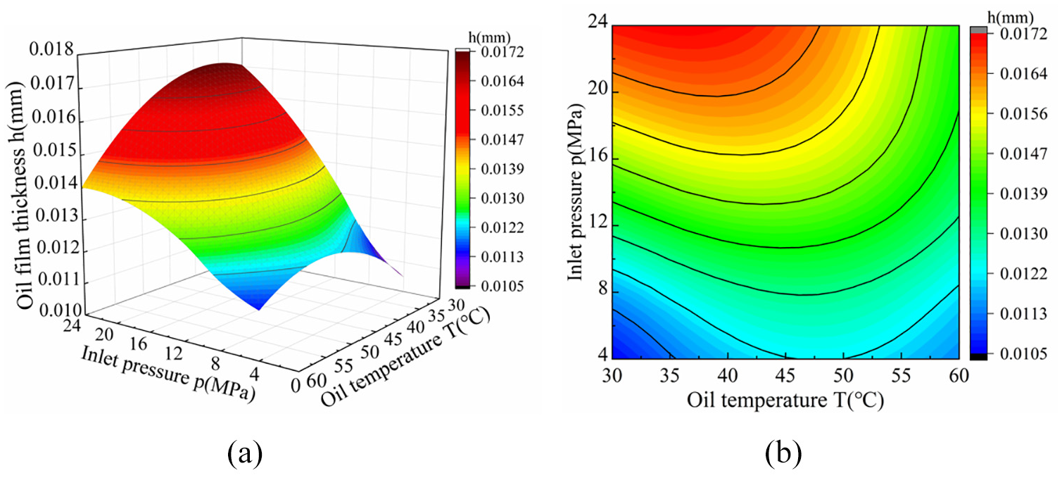
Variation of oil film thickness with oil temperature for different inlet pressures of the VPP: (a) 3D surface of the oil film thickness of the valve plate pair and (b) contour chart of the oil film thickness of the valve plate pair.
In summary, when the oil temperature is certain, the inlet pressure and oil film thickness of the VPP are linear; when the rotational speed is certain, the oil temperature and oil film thickness of the VPP is parabolic shape changes, and the oil film thickness has good stability in the temperature range of 40°C–55°C; when the inlet pressure is certain, the rotational speed has less effect on the oil film thickness. Therefore, a reasonable range of operating parameters for the motor is essential to maintain the lubricity and oil film thickness of the VPP.
Simulation of the oil film of the VPP
The geometry of the oil film in the VPP
The geometry of the oil film of the VPP of the ICHM is shown in Figure 12. The cylinder block of the ICHM is equipped with 16 uniformly distributed flow distribution holes, and its projection surface shape is shown in Figure 12(a); the valve plate is equipped with 20 flow distribution holes and 20 balance chamber oil holes, and its projection surface shape is shown in Figure 12(b). The oil film projection is formed by the contact surface of the cylinder block and valve plate; therefore, the geometric shape of the oil film is the superposition of the projected surface of the cylinder block end face and the end face of the valve plate, as shown in Figure 12(c). Its geometrical shape was irregular, and the area of the oil film through flow changes with the angle of the cylinder block. Its position is symmetrical to the geometric center of the valve plate, facilitating the calculation of the area of the oil film geometry of the VPP.
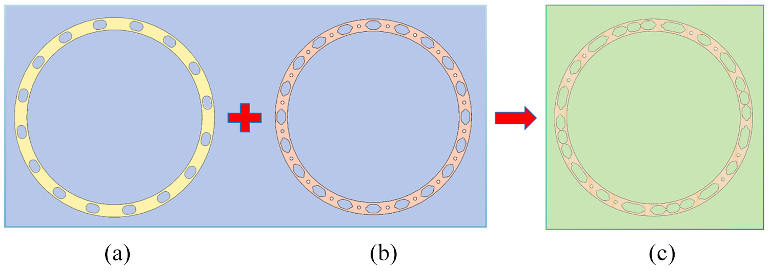
Geometry of the oil film of the VPP of the ICHM: (a) projected area of the cylinder block, (b) projected area of the valve plate, and (c) oil film shape of the valve.
Based on equation (8) and Table 1, the area of the VPP of the ICHM is shown in Figure 13, where the area of the oil film of the VPP varies cyclically within one periodic angle Δφ (4.5°) on one action surface of the ICHM. When the cylinder block angle is nΔφ (n is an integer), the maximum value of the oil film area is 7057 mm2; when the cylinder block angle1 is 1/2 nΔφ, the minimum value of the oil film area is 7022 mm2, and the oil film area fluctuates cyclically. In the case of unchanged inlet pressure, the oil film pressure distribution also changes cyclically within one periodic angle Δφ. Therefore, the pressure distribution of the oil film in the VPP can be obtained by numerically calculating the oil film with different geometries within one periodic angle Δφ.

Change the law of oil film area of the valve plate in one action surface.
Computational domain modeling of the oil film in the VPP
As shown in Figure 14, the fluid computational domain of the ICHM consists of three parts: the balance oil chamber and inlet/outlet oil chamber, the VPP, the piston chamber, and the connecting oil channel. Among them, the balance oil chambers and inlet/outlet oil channels have 20 independent computational domains; the thickness of the VPP is set to 0.015 mm, and the computational domain of the oil film is divided into five layers; the piston chamber and connecting oil channel have 16 computational domains each. The computational domains of the ICHM were structural mesh grids computed using double-precision numerical computations in ANSYS Fluent software. The solver adopted a pressure interpolation method, and was simulated using a steady-state computational scheme.

Computational model of the fluid domain of the ICHM.
In this paper, a mesh grid density of 600 K was used as the base model for the calculation of the ICHM, and the domain of the oil film calculation of the VPP domain was investigated separately. The mesh grid irrelevance was verified by increasing the mesh grid density, and four mesh grid densities of 200 K (coarse), 400 K (medium), 800 K (fine), and 1600 K (ultrafine) were used for the analysis. As shown in Figure 15, with an increase in the number of iterative steps in the numerical computation, the velocity of the monitoring point gradually tends to a stable value. The numerical calculation results were very close under 800 and 1600 K mesh grid densities, and the error was less than 3%, which indicated that the numerical calculation results were no longer affected by the change in mesh grid density, and the model calculation met the requirements of grid independence, while the numerical calculation results in the oil film computational domain were reliable. Therefore, an oil film computational domain with an 800 K mesh grid density was adopted as the research object for the oil film pressure distribution.

Variation law of the velocity at the monitoring point with the number of steps in the calculation iteration.
Boundary conditions for simulation of the oil film in the VPP
The oil film characteristics are the key entry point to study the leakage mechanism of the VPP, and the characteristic change of the oil film under different geometries can be distinctly analyzed by numerical calculation of the oil film. In Fluent software, the same working parameters as the actual working conditions of the motor were set as the calculation boundary conditions of the model. The model used the L-HM 46# hydraulic oil, the inlet pressure was set at 10 MPa, the outlet pressure was set at 0.8 MPa, oil temperature was set at 40°C. Through steady-state analysis, the pressure distribution of the oil film of the VPP under different cylinder block corners was calculated to further analyze the effect of the oil film pressure distribution on the leakage of the VPP under different cylinder block angles.
Pressure distribution law of the oil film of the VPP
As shown in Figure 16, the pressure distribution of the oil film of the VPP was within one periodic angle Δφ when the inlet pressure was 10 MPa. The pressure distribution of the oil film of the VPP varied relatively slightly under different cylinder block angles, but the pressure distribution of the oil film changed with the change in the oil film area within one cylinder block angle φ. When the cylinder block angle is nΔφ, the pressure distribution of the oil film is the same, and only the position of the flow allocation window is different. At the high-pressure oil flow inlet, the pressure distribution of the oil film gradually decreased along the flow window area, whereas the pressure distribution of the inner and outer sealing bands decreased nonlinearly along the radial direction. This is because the clearance flow at the sealing band is a radial laminar flow, the oil has a fast exit velocity, the pressure drops rapidly, and the pressure field distribution of the sealing band is directly related to its width. The high-pressure region of the pressure wrap angle in the cylinder block angle Δφ is a periodic change, according to equation (2). In nΔφ, the pressure wrap angle was the largest, and the sealing belt leakage was also the largest. In 1/2 Δφ, the pressure wrap angle was the smallest, and the leakage of the sealing band was the smallest.
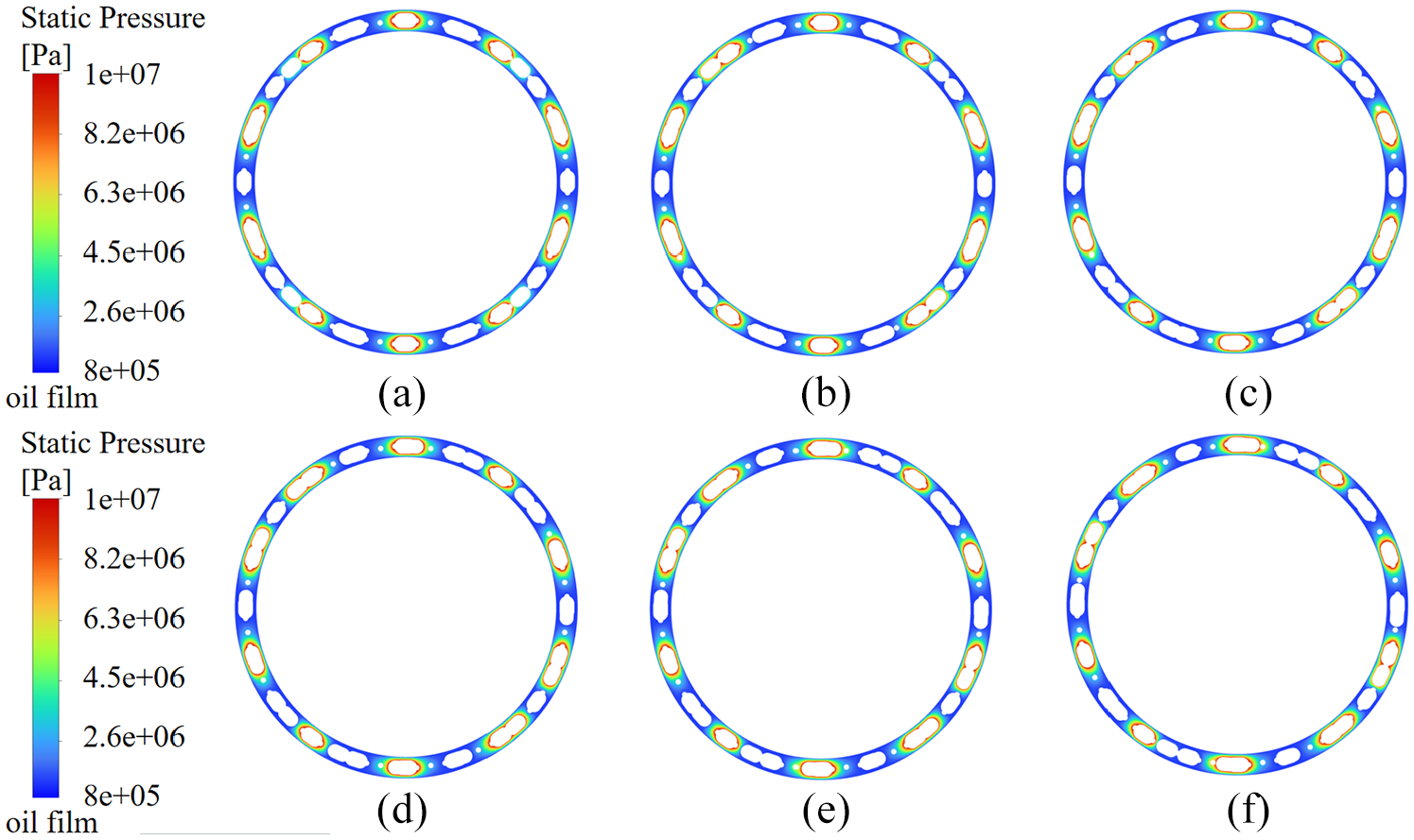
Oil film pressure distribution of the VPP in one periodic angle: (a) φ1 = 4.5°, (b) φ2 = 5.25°, (c) φ3 = 6°, (d) φ4 = 6.75°, (e) φ5 = 7.5°, and (f) φ6 = 8.25°.
The effect of oil film pressure on leakage
The leakage amount of the oil film is directly proportional to its leakage velocity without considering the vibration effect of the oil film and the constant thickness of the oil film. Therefore, the leakage velocity reflects the leakage of the oil film. As shown in Figure 17, the numerical calculation model of the ICHM was set up with six different inlet pressures, revealing the variation in the leakage velocity of the oil film of the VPP in one periodic angle Δφ. When the inlet pressure was 4 MPa, at φ of 5.25° and 8.25°, the oil film leakage velocity reached the maximum values of 2.685 and 2.698 m/s, respectively, while at φ of 6.75°, the oil film leakage velocity was the minimum of 1.732 m/s; when the inlet pressure was 24 MPa, at φ of 5.25° and 8.25°, the oil film had the maximum leakage velocities of 12.566 and 12.396 m/s, at φ of 6.75°, the oil film had the smallest leakage velocity of 10.848 m/s. This is because in one periodic angle Δφ, at φ of 5.25° and 8.25°, the pressure angle of the high-pressure area is slightly reduced compared with that at φ of 4.5° and 9°, but at this time, there are some balance chambers in which the pressure oil starts to leak; therefore, the oil film has the largest leakage velocity, and the leakage amount of the oil film of the VPP is the largest. At φ of 6.75°, the contact area of the oil film, pressure wrap angle of the high-pressure region, the oil film leakage velocity, and leakage of the VPP were the smallest. It can be seen that the oil film in one periodic angle Δφ, oil film leakage speed, and leakage amount show an ‘M’ shape distribution.

Leakage velocity of the oil film of the VPP in one periodic angle.
In summary, the geometric shape of the oil film of the VPP of the ICHM consists of the geometric projection of the cylinder block and end face of the valve plate. The area of the oil film geometry changes periodically within one periodic angle Δφ of the motor, and at 1/2 Δφ, the area of the oil film is the smallest; the pressure distribution of the oil film also changes cyclically within Δφ, in which at 1/2 Δφ, the oil film leakage velocity and leakage amount are the smallest, whereas at 1/4 Δφ and 3/4 Δφ, the oil film leakage velocity and leakage amount are the largest.
Conclusion
In this paper, the leakage mechanism of the valve plate pair of the internal curve hydraulic motor was studied. Based on the mathematical model of the internal leakage of the internal curve hydraulic motor and the theory of oil film lubrication of the valve plate pair, the leakage model of the valve plate pair was established, the effect of the motor working condition on the leakage of the valve plate pair was described, the oil film thickness corresponding to the leakage under different working conditions was deduced, and the geometric shape, pressure distribution of the valve plate pair, and the change characteristics of the leakage velocity were analyzed. The following conclusions were drawn.
The inlet pressure and oil temperature had a greater effect on the leakage of the valve plate pair, whereas the effect of the rotational speed was smaller. In addition, as the oil temperature and rotational speed increased, the leakage of the valve plate pair tended to decrease.
The effects of inlet pressure and oil film thickness of the valve plate pair were linear, the effect of oil temperature on the oil film thickness of the valve plate pair was parabolic shape changes, and the oil film thickness was stable in the temperature range of 40°C–55°C, whereas the effect of rotational speed on the oil film thickness was not obvious.
The geometric shape of the valve plate pair oil film and pressure distribution in one periodic angle with the internal curve hydraulic motor changes cyclically, the pressure field of the oil film in the inlet area is surroundings distribution, the pressure at the seal zone along the radial direction of the pressure is a nonlinear trend of decreasing, and the leakage velocity of the oil film and the leakage amount of the ‘M’ shaped distribution.
In summary, the oil film thickness is the main factor affecting the leakage of the valve plate pair, whereas the oil film pressure distribution is the key factor determining the leakage of the valve plate pair. Through the combination of a theoretical model and numerical calculations, this study provides a theoretical basis for analyzing the leakage mechanism of the valve plate pair and designing a variable pressing force on the valve plate.
Footnotes
Handling Editor: Michal Stosiak
Funding
The author(s) disclosed receipt of the following financial support for the research, authorship, and/or publication of this article: This research was funded by the Open Foundation of the State Key Laboratory of Fluid Power and Mechatronic Systems, grant number 2022YFC2805702.
Declaration of conflicting interests
The author(s) declared no potential conflicts of interest with respect to the research, authorship, and/or publication of this article.