
Abstract
In order to increase efficiency and reliability of hub motor power device for distributed driving electric vehicle, a novel hub motor with an external rotor PM (permanent magnet) is designed and optimized. The performance parameters of hub motor are computed and selected based on vehicle dynamics indicators and the driving equations. This paper determines the optimum primary size of hub motor by choosing appropriate magnetic circuit structure and integrating three key parameters, including as stator split ratio, electromagnetic load and viscous damping coefficient. This paper has built the analysis model of external rotor PM hub motor, and simulated and analyzed the transient magnetic field of hub motor under no-load and load transient or steady state. Simulation results indicate that the external rotor PM hub motor designed by combining stator split ratio, electromagnetic load and viscous damping coefficient has satisfactory electromagnetic performance, which can satisfy the performance requirements and indicators of hub motor power device for distributed driving electric vehicles.
Keywords
Introduction
Under the context of global saving energy and reducing emission, the electric vehicles are becoming more and more important for various countries,1,2 and modern electric vehicles need use high-performance in-wheel motors. 3 The magnetic field is regarded as the medium, which is used to convert electrical energy into mechanical energy for the hub motor of electric vehicle. 4 In motors, the magnetic field distribution and associated magnetic properties directly affect the performance of hub motor. 5 Therefore, it is very important to analyze and simulate the electromagnetic performance and indicators of hub motor for distributed driving electric vehicles.
At present, scholars at home and abroad have done some researches on electromagnetic design and simulation of hub motor for electric vehicle. 6 Su et al. 7 designed the electromagnetic performances and determined the number of poles and slots of hub motor, but the method of determining the main dimensions of hub motor was not given. Sheng et al. 8 designed and simulated the hub motor, but only the electromagnetic loads and viscosity damping coefficient of the motor were considered in the design process, and the split ratio selection was ignored. Lei et al. 9 designed, simulated and tested the prototype motor, but only the electromagnetic load of motor was considered during design process. Andrada et al. 10 determined the key parameters of hub motor, and carried out electromagnetic field simulation. However, the electromagnetic design process of hub motor was not given. Si et al. 11 analyzed the relationship between the physical fields of the motor, and a design method of multi-physical fields of PM fault-tolerant hub motor was proposed, which improved the reliability of the hub motor. Fard et al. 12 optimized a new model of PM motor for axial magnetic flux switch sandwich and made a model of 12S/19P AFFSSPM motor. High torque and low speed direct drive can be realized. Hanaeinejad and Abbasian 13 has studied an external rotor switched reluctance motor with non-segmented rotor and short magnetic path, which can save rotor cage and only need a shell to maintain the rotor. This configuration can reduce the motor components used in in-wheel electric vehicles. Song et al. 14 adopted an multi-objective optimization design method to improve the particle swarm. The different PM synchronous motors was optimized, which was used to propose an optimization algorithm with efficiency, flux weakening rate and price, which was regarded as the optimization goal, and the feasibility of the multi-objective optimization design method was verified. Zhang et al. 15 developed a new type of hybrid excitation alternator. The electromagnetic coupling regulator controller was designed, which is used to solve the problem of unstable output voltage of hybrid excitation alternator, when it was in the wide speed and load range.
This paper has analyzed and studied the brushless PM hub motor for the outer rotor of electric vehicles. A more accurate and reliable electromagnetic design method is proposed, which was used for analyzing the size and performance requirements of hub motor, based on some key parameters, the hub motor analysis model is built. This paper also simulates and analyzes the magnetic field distribution and electromagnetic characteristics of hub motor for distributed driving electric vehicles.
Determination of performance parameters
PM brushless direct current motor is selected as hub motor in this paper. The maximum speed, slope and acceleration time of the vehicle are used to compute the rated power of hub motor for distributed driving electric vehicles. The key parameters for distributed driving electric vehicles are expressed in Table 1, and the main performance indicators for the whole vehicle are expressed in Table 2.
The key parameters.

The main performance indices.

Electric vehicle power Pe can be expressed as equation (1). 16

Here,
The maximum speed of an electric vehicle is regarded as an indicator of the power of hub motor, and the authors have only taken into account the rolling resistance and the air resistance, the equation may be represented as equation (2). 17
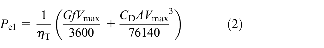
Relevant data of Tables 1 and 2 are plugged into equation (2), and then Pe1 is calculated, which is 50 kW.
The electric vehicle acceleration time is regarded as the indicator, which is used to determine the power of the drive motor, and this paper has only taken into account the air resistance power, the rolling resistance power and the acceleration resistance power, the equation is shown in equation (3). 17
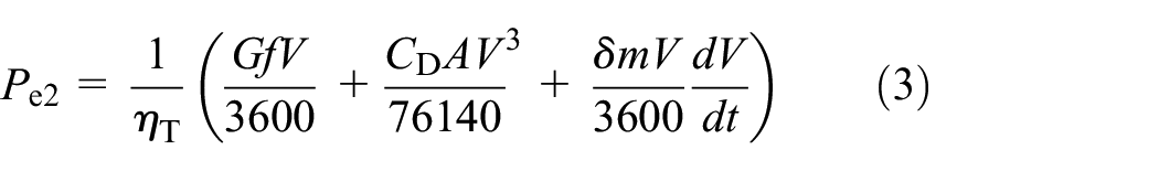
Here, V is the normal vehicle speed, and the acceleration is calculated by acceleration performance index dv/dt, which is 3.47 m/s2 based on Table 2. Relevant data of Tables 1 and 2 are plugged into equation (3), and then Pe2 is calculated, which is 78 kW.
The maximum slope of an electric vehicle is regarded as the indicator, which is used to determine the power of the drive motor, and this paper has only taken into account the air resistance power, the rolling resistance power and the gradient resistance power, the equation is shown in equation (4). 17

Relevant data of Tables 1 and 2 are plugged into equation (4), and the grade ability of electric vehicle under full load is considered, and then Pe3 is calculated, which is 11 kW.
Based on above calculation results, the drive motor power is determined by the acceleration time of electric vehicle peak power, which is 78 kW. The distributed driving electric vehicle is regarded as study object, and each vehicle wheel is operated independently, which is also called the hub motor drive mode, so the peak power of each hub motor Pemax≥20 kW. When the maximum speed of electric vehicle is regarded as the calculated index, and the overload coefficient of motor is
The torque of the hub motor must satisfy following expression equation (5). 19

And the relationship between torque, power and speed of the wheel at any time must satisfy the following expression equation (6). 19

Because the external rotor PM brushless direct current motor is used in this paper, so the value ig and i0 is 1. When the maximum speed of distributed driving electric vehicle often corresponds to the maximum speed of hub motor, then the highest speed of wheel can be shown in equation (7). 19

Relevant data is plugged into equation (7), and then nmax is calculated, which is 1232 r/min.
Based on the above analysis, the relevant performance parameters of the hub motor are determined, which is expressed in Table 3.
Hub motor performance parameters.

Main size calculation
PM brushless direct current motor has a variety of magnetic circuit structures, which may be divided into radial and tangential magnetic circuit according to the direction of air gap flux, which also can be divided into a surface and interior magnetic circuit structure according to the PM installation position.20,21 According to the performance index of hub motor, the multi-stage outer rotor surface-mount magnetic circuit structure is most suitable. The main sizes of PM brushless direct current motor are the stator core diameter Da and the stator core length L. In this paper, the determination of main size of hub motor by integrated stator crack ratio method, electromagnetic load determination method and viscous damping coefficient method.
Stator split ratio
The stator split ratio can be expressed as equation (8).

The difference between the stator outer diameter Da and inside diameter of stator

The selection of the stator split ratio is related to the PM material, when the PM material with low air-gap flux density is selected, the stator yoke high is small, and then larger stator split ratio should be taken. When the value of the pole number is large, or tooth number of the concentrated winding of the fractional slot is large, the stator yoke high will be small, and then larger stator split ratio should be taken.
Electromagnetic load
The average electromagnetic torque Tav of PM brushless direct current motor can be expressed as equation (10). 23

Where,
The related parameters are defined by equation (10).
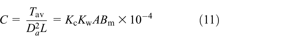
According to equation (11), the stator outer (air gap) diameter Da and the stator core length L are the main factors affect the motor electromagnetic torque. Electromagnetic load ABM reflects the utilization of motor materials, the higher the electromagnetic load, the higher the utilization of electrical materials. However, when the electromagnetic load is too large, the copper loss and core loss of the motor will be increased, resulting heating and temperature rising of the motor, then reducing the motor efficiency. Therefore, the intrinsic mechanism of basic relationship between the main sizes of the motor is: reflect motor loss-heat-heat dissipation problem, select correct main sizes to satisfy the index of efficiency and heat-heat dissipation of motor.
Viscous damping coefficient
In PM brushless direct current motor, the viscous damping coefficient D reflects the hardness of mechanical properties of motor, the response speed of system, the electromagnetic efficiency and the efficiency of motor. 24 When ignore the motor winding inductance, the relationship between viscous damping coefficient D and main sizes of motor can be expressed as equation (12).

Where, KD is the comparison coefficients of viscous damping coefficient, KS is the coil space factor rate, As is a single stator slot area (mm2), Z is the stator slot number,
From equation (12) it can be know that using better magnetic materials and designing reasonable magnetic path to increase the density of the magnetic flux, and improve the main sizes
Based on above theoretical analysis and calculation, and correlative hub motor geometric parameters are optimized and obtained through RMxprt of Maxwell soft, as shown in Table 4.
Hub motor geometric parameters.

Simulation and analysis
A geometric model of hub motor is built, and when the hub motor is in the steady-state operation, the transient magnetic fields of hub motor are simulated and analyzed under no-load and load transient or steady state
Analysis of no-load transient magnetic field
The magnetic field lines distribution of hub motor at the initial moment under no-load transient is expressed in Figure 1. The magnetic field lines distribution of hub motor at 0.28 s motion under no-load transient is expressed in Figure 2. Figures 1 and 2 show that there is no serious leakage phenomenon in the hub motor internal either initial moment or movement moment. Within the rotor, the magnetic field lines form eddy currents through the gap of the PM, and the magnetic field lines are evenly distributed. Within the stator, the magnetic field lines of hub motor are mainly distributed around the stator grooves, and the magnetic field line through the stator groove is very small, which conforms to the magnetic field lines distribution of hub motor.

Magnetic field lines distribution of hub motor at initial moment under no-load transient.

Magnetic field lines distribution of hub motor at 0.28 s motion under no-load transient.
Magnetic flux density cloud chart of hub motor at the initial moment under no-load transient is expressed in Figure 3, and magnetic flux density cloud chart of hub motor at 0.28 s motion under no-load transient is expressed in Figure 4. Figures 3 and 4 indicate that the largest magnetic flux density appears at part of the stator tooth end near the air gap, and the maximum flux density reaches 1.8 T. The magnetic flux density distribution of PM is relatively uniform, the magnetic flux density of air gap is also uniform, and its value is slightly smaller than in PM. The larger stator magnetic flux density is mainly concentrated in the adjacent stator grooves. The rotor magnetic flux density is mainly distributed near air gap. When the rotor is farther away from air gap, the magnetic flux density is smaller.
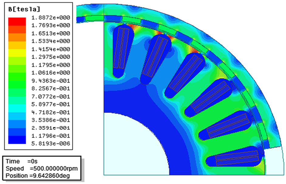
Magnetic flux density cloud chart of hub motor at the initial moment under no-load transient.

Magnetic flux density cloud chart of hub motor at 0.28 s motion under no-load transient.
The cogging wave of hub motor under no-load is expressed in Figure 5. Figure 5 indicates that cogging torque of hub motor has an unsteady amplitude sinusoidal fluctuation with time, which symmetry is better. Cogging torque display periodic variation, and its maximum value is less than 2 N·m, smaller than rated torque of motor that is normal.
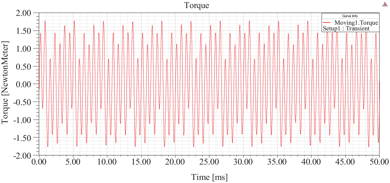
Cogging wave of hub motor under no-load.
Analysis of transient magnetic field under steady state
Magnetic field lines distribution of hub motor at initial moment under steady state is shown in Figure 6. Magnetic field lines of hub motor distribution at 0.1 s motion under steady state is shown in Figure 7. Figures 6 and 7 show that the magnetic field lines distribution of hub motor under steady state is almost same as the magnetic field lines distribution at 0.1 s motion under steady state. There is no magnetic saturation phenomenon at stator tooth end or other parts.

Magnetic field line distribution of hub motor at initial moment under steady state.

Magnetic field line distribution of hub motor at 0.1 s motion under steady state.
Magnetic flux density cloud chart of hub motor at load transient initial moment under steady state is expressed in Figure 8. Magnetic flux density cloud chart of hub motor at 0.1 s motion moment under steady state is expressed in Figure 9. Figures 8 and 9 indicate that the maximum magnetic flux density still appears at the stator grooves end near the air gap, but is unlike the rated uniform motion state, and magnetic flux density has increased especially in the stator under 0.1 s motion moment. The stator grooves end magnetic flux density is 2.7 T near the air gap.

Magnetic flux density cloud chart of hub motor at load transient initial moment under steady state.
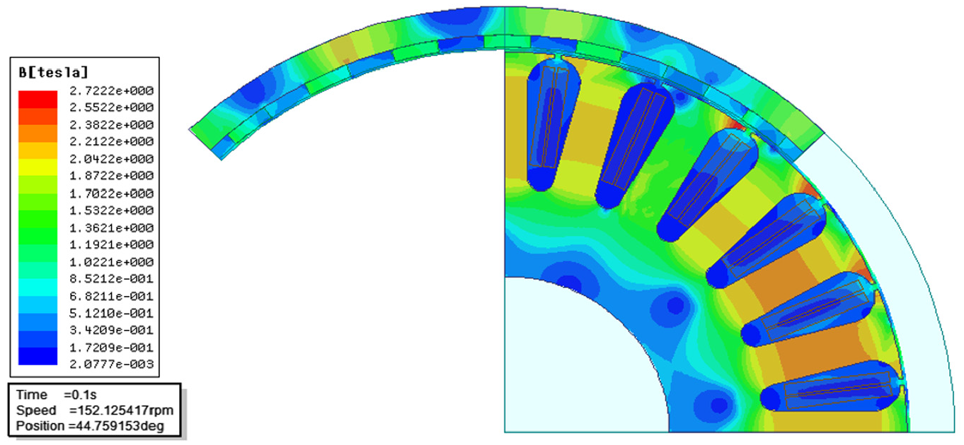
Magnetic flux density cloud chart of hub motor at 0.1 s motion moment under steady state.
The electromagnetic torque curve during operation is shown in Figure 10. Figure 10 indicates that the hub motor electromagnetic torque increases quickly and reaches a peak torque of 660 N·m around 10 ms during the motor initiating stage. After hub motor is started, electromagnetic torque starts to decrease as a whole around 50 ms, there are many large fluctuations in the decrease process, and the electromagnetic torque starts to stabilize at 140 ms and stabilizes between 225 N·m and 285 N·m. The process of changing the electromagnetic torque curve reflects the process from mechanical starting process to stable running state of the motor, and the process of electromagnetic torque rapidly increases to the steady state coincidence with theoretical trend.

Electromagnetic torque curve during operation.
Conclusions
Performance parameter of hub motor is determined based on dynamic performance indicators of distributed driving electric vehicles. This paper analyzed and designed the electromagnetic characteristics of hub motor, and also simulated and analyzed the electromagnetic field of hub motor by Ansoft software. The research of this paper draws the following conclusions.
The performances of hub motor are closely connected with the stator split ratio, electromagnetic load and viscous damping coefficient. There are three key parameters, which are the stator split ratio, electromagnetic load and viscous damping coefficient, and the three key parameters are integrated and analyzed, which is used to determine the main sizes of hub motor, and further analyze and increase the performances and reliability of hub motor power device for distributed driving electric vehicle.
The maximum magnetic flux density at the stator grooves end is close to the air gap, and then it is larger magnetic flux density between permanent magnet and stator grooves, and there is a slightly lower magnetic flux density between the stator grooves.
The hub motor is designed in this paper, which is a large electromagnetic torque and is small fluctuation range at the initial moment of starting, which gradually decreases and finally fluctuates within stable range, which can satisfy the performance requirements and indicators of hub motor, in order to increase efficiency and reliability of hub motor power device for distributed driving electric vehicle.
Footnotes
Acknowledgements
The authors would like to thank the encouragement of the editor and anonymous reviewers for their helpful comments and suggestions to improve the manuscript.
Handling Editor: James Baldwin
Declaration of conflicting interests
The author(s) declared no potential conflicts of interest with respect to the research, authorship, and/or publication of this article.
Funding
The author(s) disclosed receipt of the following financial support for the research, authorship, and/or publication of this article: This research was supported by the Foundation of Educational Department of Jiangxi Province (Grant No. GJJ190305).