
Abstract
With the rapid development of the world economic construction and the shortage of energy, it has become a hot research issue to realize the electrification of the vehicle driving system and improve energy efficiency. Most of the electric construction machinery power systems are characterized by low speed and high load. The coordinated driving of multiple motors can increase the output torque and improve the transmission efficiency of the machine on the basis of a compact layout. A novel configuration of electric construction vehicles based on multi-motor and single-speed and its driving torque distribution control method is presented in this paper. The detailed mathematical model is established and the simulation analysis is carried out based on it. The results show that the proposed multi-motor driving system with the control strategy can improve the overall efficiency in the condition of ensuring the driving force when the parameter matching and motors choosing reasonably.
Keywords
Introduction
In recent years, in order to achieve the goal of reducing greenhouse gas emissions from fossil fuel combustion and improving the overall efficiency of vehicles, 1 the development of vehicle electric transmission technology is changing rapidly, and the electrification proportion of construction machinery in the market is also increasing year by year. 2 In the past decade, the research on new energy vehicle technology, represented by hybrid electric vehicles and electric vehicles, has made pioneering achievements.3–5 How to better apply electric transmission technology in the field of construction machinery is an urgent problem to be solved.
In the existing electric construction machinery, the driving motor system should meet the requirements of better output characteristics, wider speed range, faster response, higher efficiency, firmer structure, less weight, and other requirements. Due to the large working resistance of construction machinery in the driving and operating period, the main requirements of the driving motor are low speed, high torque, and high power to satisfy the working performance of the construction machinery. Effectively controlling the driving motor is the key to realizing vehicles running according to the driver’s intention. The current control methods of A/C motor mainly include direct torque control and vector control with the slip frequency control. Reasonably matching the driving system and optimizing the working interval of the motor to make it work in high efficiency are the key technologies in electric construction machinery. 6
Multi-motor driving system can effectively save energy on the premise of ensuring the dynamic performance of vehicles.7–9 At present, single-speed transmission electric vehicle driven directly by motors has been widely developed and applied.10,11 This transmission scheme has the advantages of convenient torque control and high transmission efficiency. However, the driving system of this scheme cannot control the working point according to the torque and speed of the motor. 12 At this time, the driving motor can only operate in the low-efficiency range under certain working conditions. In addition, due to the limitation of the single gear transmission ratio, the system with variable transmission ratio can be changed according to different working conditions, so as to improve the dynamic performance of the system more reasonably.
In order to obtain a better performance and a higher efficiency than a single-motor-multi-speed driving scheme, a lot of research on multi-motor-multi-speed electric vehicles has been done by researchers. Results showed that the efficiency of multi-motor-multi-speed electric vehicles is higher than that of single-motor-single-speed electric vehicles. 13 A single-motor-two-speed electric vehicle was compared with a single-motor-single-speed electric vehicle in other researches to confirm its better performance and efficiency. Design parameters, such as shift modes, 14 torque distribution,12,15,16 and the transmission ratio, 15 were optimized to improve energy efficiency in these studies. Such researches have a common drivability problem when there is a gear shift mechanism in the transmission system. Additional shift control logic has been proposed to solve this problem.12,13 Torque interruption during gear shifting is basically impossible to solve because that power must be cut off to maintain the synchronization. 17 Research 14 proposed a two-motor coaxial coupling propulsion system as a solution.
In the power system of electric vehicles without gearshift, the number of motors driven gears is the same. It is not necessary for a separate gearshift since each motor is connected to each gear, so there is no torque interruption and high transmission efficiency is achieved. 18 The system requires proper gear ratio estimation and additional control motor torque distribution to improve performance and efficiency. 15 Therefore, the key to maximizing the advantage of the system is to put forward an optimization method considering both transmission ratio and torque distribution.
In the research mentioned above, some paid great attention to the driving system model and motor control method of hybrid or pure electric road vehicles 19 but ignored some off-road vehicles 20 with the low-speed and heavy-load conditions. Most of these studies involve road vehicles driven by two motors, and few involve more than three driving motors. On the other hand, some theoretical and experimental studies on multi-motor driving systems are mainly focused on the dynamic characteristics of electromechanical system of some large construction machinery, such as the synchronous characteristics of the cutter head drive system of tunneling machine under impact load.21,22
At present, there are few research on coordinated control methods for stability and economy of multi-motor driving system based on torque distribution for construction machinery. In this paper, the motor switching and torque distribution of multi-motor driven wheeled construction vehicles are studied in order to improve the vehicle energy efficiency without changing the working performance of construction machinery. Works are organized as follows. The mathematical model of the proposed multi-motor driving system is introduced in section 2. In section 3, the motor shifting control method and the multi-motor coordinated driving control strategy are proposed. Then, simulation results of the vehicle driven by a single 45 kW motor and three 15 kW motors are presented and compared in section 4. Finally, section 5 shows the conclusion.
Mathematical model of the driving system
In this paper, a new type of coupling driving system structure of electric driving construction machinery based on multi-motor and single-speed drive is proposed. Its structure schematic diagram is shown in Figure 1. Its feature is that the three drive motors can switch freely according to the load during construction machinery operation, with flexible power distribution space, and improved energy efficiency under the condition of traction.

Proposed multi-motor coordinated driving system.
To fully study the dynamic performance of the proposed driving system and put forward a proper multi-motor coordinated driving control strategy, a detailed mathematical model including the transmission, vehicle, and motors are established.
Resistances of construction machinery mainly contain driving resistance

The load torque is presented as:

where m is the mass of the construction vehicle, φ is the slope gradient of the road, μ is the dynamic friction coefficient and R is drive wheel radius.
It is proved that an electric motor is more efficient than an engine. Therefore, one 45 kW three-phase asynchronous motor and three 15 kW permanent magnet synchronous motors are used in the single-motor drive scheme and multi-motor drive scheme separately. Motor efficiency contour maps are shown in Figure 2. The rated engine power of the traditional fuel construction machinery referred to in this paper is 45 kW, so the total power of the electric drive scheme is also set at 45 kW. Considering the spatial arrangement of motor and gear transmission in engine nacelle, the most reasonable number of motor is three at present.
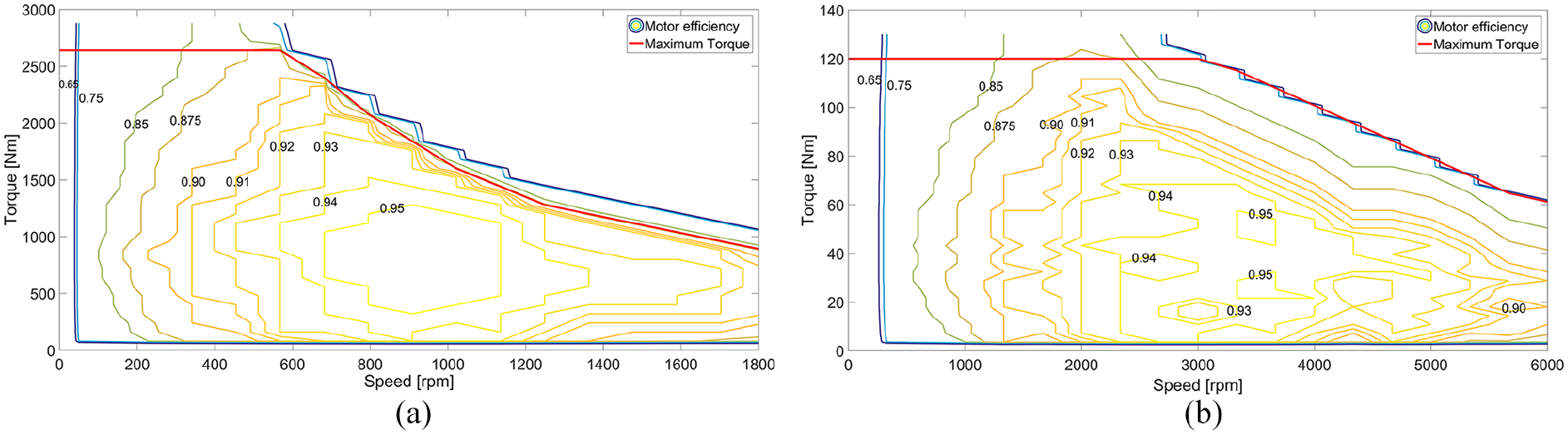
Motor efficiency contour maps: (a) 45 kW three-phase asynchronous motor and (b) 15 kW permanent magnet synchronous motor.
Figure 3 shows the proposed multi-motor driving system, where J represents the rotational inertia in the driving system. K and C represent stiffness and damping between every two parts respectively. Subscripts M1, M2, M3 represent three different motors, S1, S2, S3 represent the synchronous between motors and driving gears. Subscripts G1, G2, G3 represent driving gears, and subscripts 4 is the driven gear. subscript 5 and 6 are half shafts, subscript 7 and 8 are driving wheels. In the multi-motor driving scheme, the three motors are connected to the driving gear G1, G2, G3 through the synchronizer respectively, driving the driven gear 4 and transferring the power to the left and right half-shafts. Full lines represent rigid coupling and dotted lines represent gear meshing. G1, G2, G3 are respectively connected with G4 for gear transmission.

Dynamic model of proposed three motor driving system.
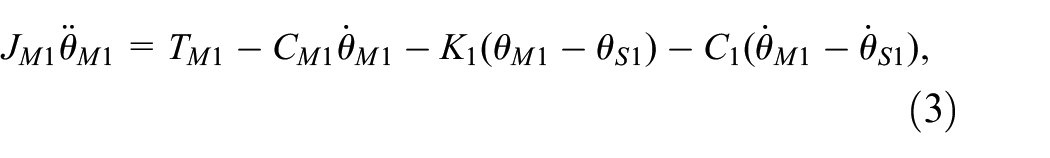
Assuming that there is no eccentricity in the driving system, the mathematical model of the dynamic system can be expressed as the following equation. The three motors are respectively shown in formulas (3)–(5).


where


where
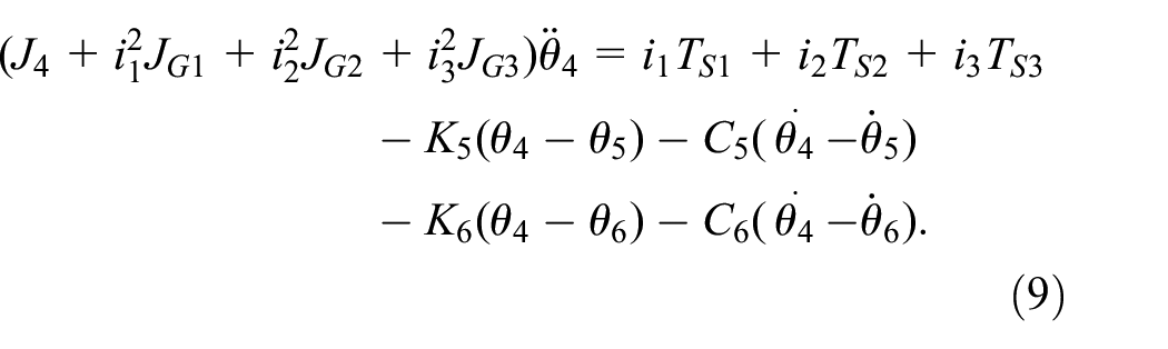
The partial dynamic model of the two half axes and the driving wheel is shown in formulas (10), (11) and formulas (12), (13).


TV is the load torque of the vehicle. When the three motors are fully connected with the synchronizer, a complete transmission chain is formed, and the motor is just connected with the driving gear respectively. At this time, formulas (6)–(9) can be simplified as:

In this paper, a simple cone synchronizer is used to connect the power, which mainly acts on the speed synchronization stage of the power system. The synchronizer model is shown in the formula (15).

where
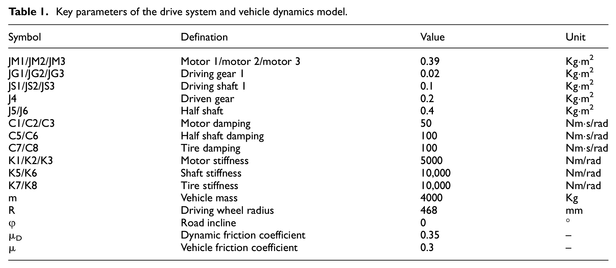
The key parameters of the driving system and vehicle dynamics model are listed in Table 1.
Key parameters of the drive system and vehicle dynamics model.
Proposed multi-motor coordinated driving control strategy
Compared with the traditional single-motor drive system, solving the shift control problem can only guarantee driving comfort and the continuity of power flow during the shift. In order to maximize the overall efficiency and meet the acceleration requirements, it is necessary to design a reasonable power-sharing control strategy to realize the power distribution among multiple motors. Each motor can be operated individually or in combination to provide the required power and desired efficiency. For example, when the speed is high and the acceleration is not required much, a single motor works alone to provide all the power. If the power provided by the first motor is exceeded under low speed and heavy load, the other motors can provide power together. Under the multi-motor coordinated drive control strategy, the proposed system can provide torque compensation for the driving motor when the vehicle load is too high, as shown in Figure 4. A transport delay unit is added to the control system to avoid some unnecessary shift with a very short time to make the shift more reasonable.

Multi-motor coordinated driving control strategy.
The multi-motor coordinated driving control strategy can be divided into two parts: load increasing driving and load decreasing driving, see Figure 5.The torque demand of each motor is determined by the multi-motor coordinated control strategy before the number of driving motors is determined. When the judgment condition is reached, the controller will take over the control of the motor speed, torque, and the connection of the synchronizer. The specific control steps are as follows.

Shifting method of the motor.
Load increasing driving:
Driving state estimate. When the vehicle is driven by i motors, current speed and load data are collected. According to the motor efficiency contour map, the efficiency of the motor under current torque and speed are analyzed. If the load torque is higher than the upper limit of the motor efficiency contour map under the current speed, it is judged to increase the number of driving motors in the system.
Motor speed synchronization. Motor (i+1) starts and switches to the speed control mode. Motor (i) keeps the current speed to prove the power is always connected.
Synchronizer Connecting. When the speed of the motor (i+1) is consistent with that of the current working motor (i), the synchronizer will connect the driving motor with the driving system.
Multi-motor synchronous driving. After the synchronizer is fully connected, the torque of the motor (i+1) is increased gradually torque of the previous working motors is reduced until it reaches the equilibrium state, at which time the vehicle is jointly driven by i+1 motors.
Reduce drive to 3 steps
Driving state estimate. When the vehicle is jointly driven by i motors, if the motor load torque at this speed is lower than the lower limit of the set efficiency range value, the number of driving motors will be reduced.
The synchronizer will be cut off and the motor (i) will be shut down.
The output torque of other motors will be increased synchronously until meeting the load demand. At this point, the vehicle is driven by i-1 motors.
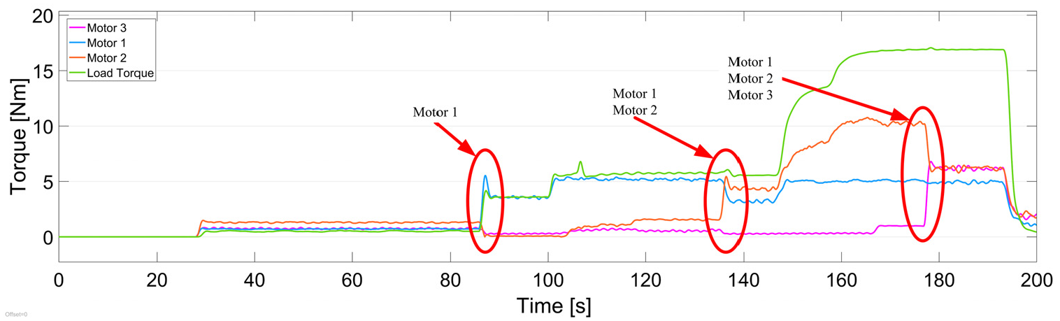
In order to prevent the impact of the rapid change of speed and torque on the motor drive system during motor switching, this paper refers to the bell function and makes modifications to it. The modified bell function curve is applied to the transition stage of motor switching under different working conditions, as shown in formulas (16) and (17).

Where

Where t0 is the start time of torque transformation, tD is the designed time length of torque transformation.
As shown in Figure 6(a), the curve transformation is slow in the initial stage, so that the torque of the transmission shaft can match the motor torque as much as possible. After that, the curve will rise with a large slope, quickly approaching the target value. Figure 6(b) shows the process of the motor descending from the current drive torque to the target drive torque.

Torque transition process: (a) increasing process and (b) reducing process.
To more intuitively reflect how the smooth transition of torque can be specifically applied to the coordinated drive control strategy of multiple motors, and verify the feasibility of the torque distribution method, the simulation results are shown in Figure 7.

Torque distribution control based on bump function transition: (a) simulation of all motor shifting process and (b) motor 1 torque reducing process and motor 2 torque increasing process.
Results and discussion
Figure 8 shows the working conditions of a conventional fuel construction vehicle. Figure 8(a) shows the curve of the final load torque and Figure 8(b) shows the curve of driving wheel speed. The data including five complete working cycles was tested in an actual working condition of 200 s. It is present that a complete working cycle is about 40 s. The maximum final load torque is about 1800 NM and the maximum speed of final transmission is about 1000 r/min. The test data is collected from a fuel loader as shown in Figure 9.

Test data of a conventional fuel construction: (a) final load torque and (b) driving wheel speed.

Data collection of the loader.
Simulations of one motor and multi-motor driving configuration are carried out in this paper. Figure 10 shows the output torque of the motors when the vehicle is driven by one 45 kW permanent magnet synchronous motor and three 15 kW permanent magnet synchronous motors based on the multi-motor coordinated drive control strategy proposed in this paper respectively. The output torque fluctuation of the multi-motor driving scheme is lower than one motor driving scheme.

Output torque of the 45 kW motor and 15 kW motors.
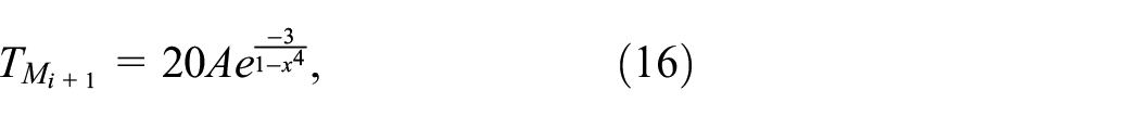
As shown in Figure 11(a), the working points of the 45 kW motor are mainly distributed at low speed and low torque area. Figure 11(b) to (d) show the working efficiency points of 15 kW motors 1, 2, and 3 separately. Among them, motor 1 and 2 have a high frequency of use, and the working points are widely distributed. Motor 3 has a low frequency of use, which is mainly working at low speed and high torque situation. It is present that vehicles driven by multi motors make the working range more reasonable.
Working points of the driving motors: (a) 45 kW motor, (b) 15 kW motor 1, (c) 15 kW motor 2, and (d) 15 kW motor 3.
Figure 12 shows the efficiency of the 45 kW driving motor and three 15 kW driving motors. It can be seen that when the vehicle is driven by the multi-motor configuration, the 15 kW motor 1 is still working all the time. When the vehicle is working at a high speed and low load working condition, the working motors are mainly 15 kW motor 1and 15 kW motor 2. The efficiency of all working motors is above 90%, and two 15 kW motors are more efficient than 45 kW motor obviously. In the low speed and high load working condition, three 15 kW motors are all working at that time. The efficiency of all motors is between 70% and 90%, and three 15 kW motors are more efficient than 45 kW motor most of the time. In the low speed and low load working condition, the vehicle is only driven by 15 kW motor 1 and the motor efficiency is below 70%. Only at that time, the efficiency of 45 kW motor is a little higher than 15 kW motor. It can be seen that the low speed and low load working condition appears only three times in every single working cycle with a short period. Therefore, it has little effect on overall efficiency

Efficiency of the 45 kW motor and three 15 kW driving motors.
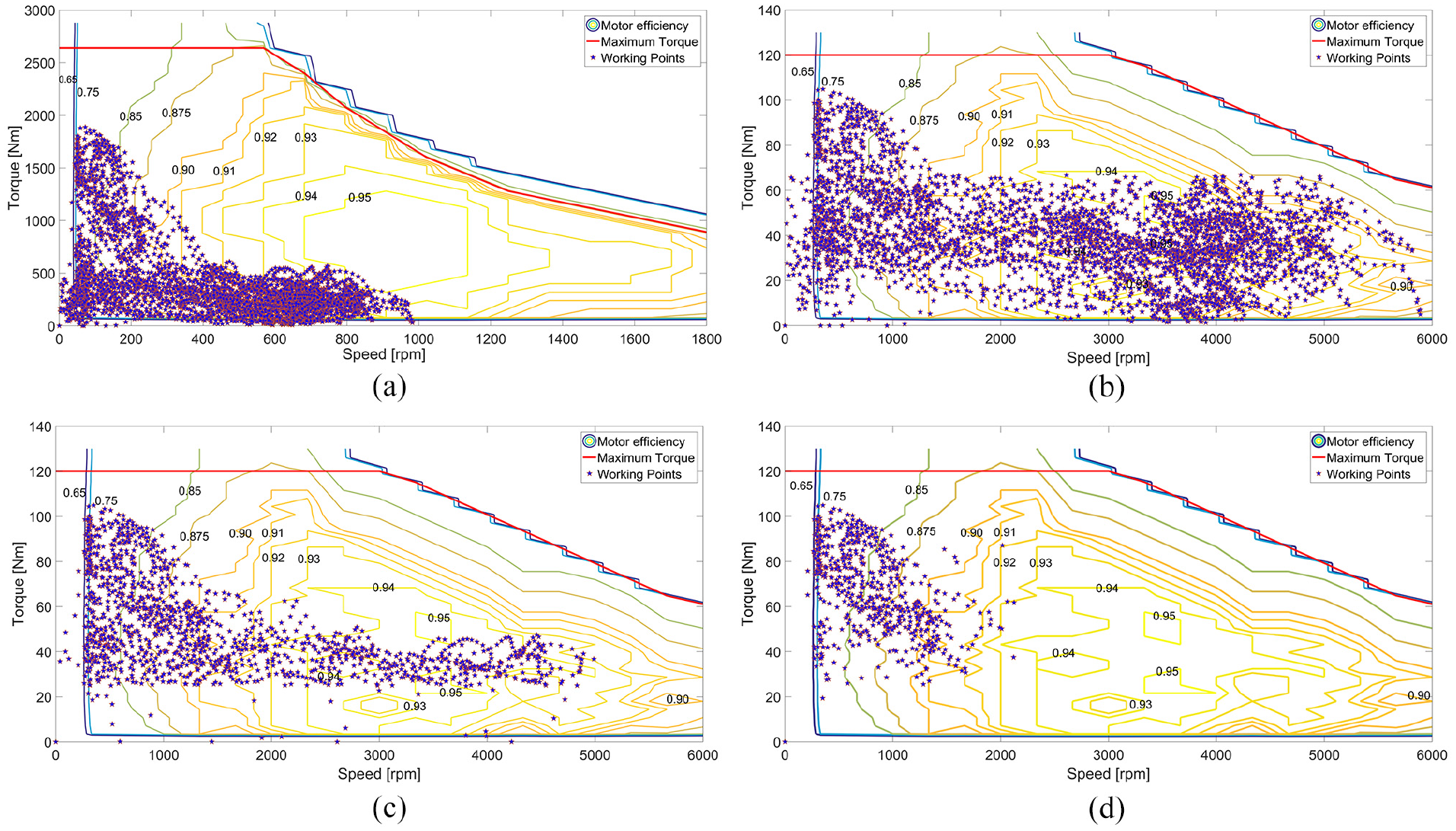
Figure 13 records the total energy consumption of the driving motors under two driving configurations during six working cycles in 200 s. The energy consumption of the 45 kW single motor is 0.852 kW•h. Under the proposed multi-motor driving scheme and control strategy, the total power consumption of three 15 kW motors is 0.812 kW•h.
Energy consumption of two electric driving configurations.
In order to evaluate the proposed multi-motor coordinated driving control strategy, a test bench was established. It is difficult to be completely consistent with the actual power source of construction machinery due to the limitation of experimental conditions. So three identical small power motors are selected as the power source of the multi-motor driving system test bench. The three input shafts and the output shaft are respectively equipped with torque sensors. The output shaft is connected to the loading device to simulate the external load. Figure 14 shows the test bench structure.

The test bench structure.
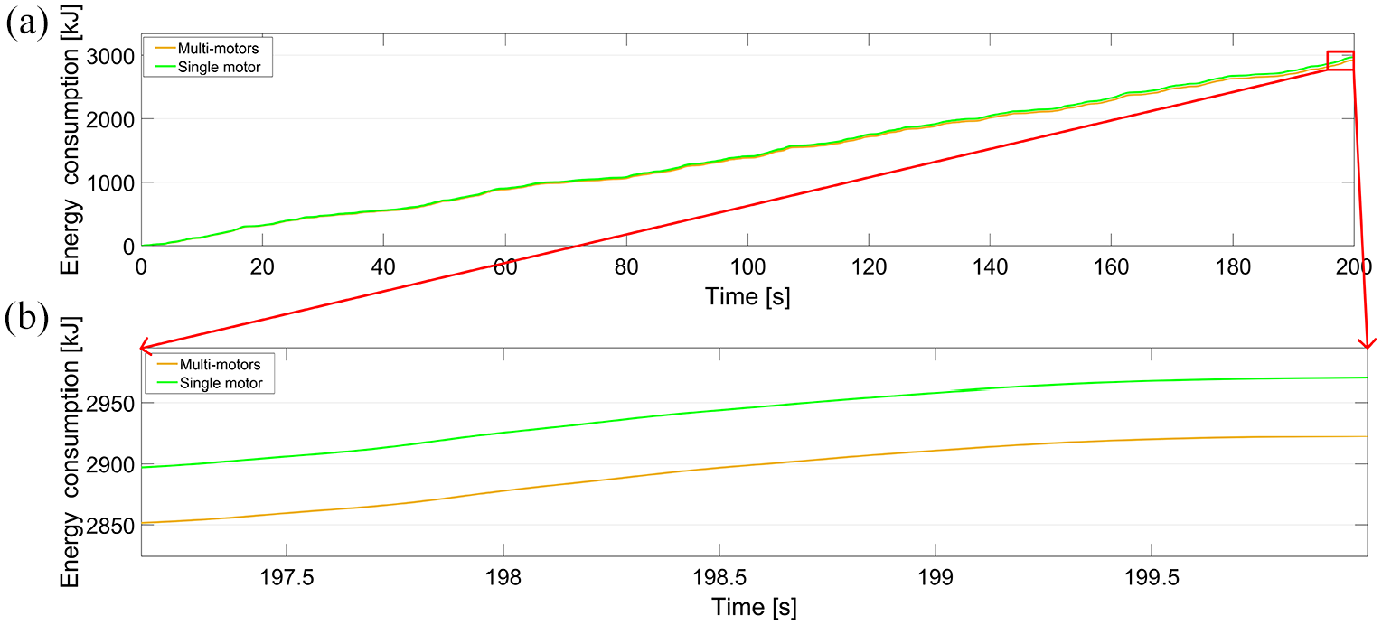
Figure 15 shows the external load torque measured by the test bench and the driving torque of the three motors. From 0 to 85 s, the load torque is 0. At this time, the motor only overcomes the internal resistance of the system. At 85 s, the load torque increases, and the driving torque of motor 1 is equal to the load torque. At 140 s, the driving torque of motor 1 decreases, and at the same time, motor 2 gets involved. At this time, the system is driven by motor 1 and motor 2 jointly. As the load torque continues to increase, at 180 s, motor 3 gets involved, and the system is driven by three motors simultaneously. It can be seen from the test data that motor 1 is always in working state, while motor 2 and motor 3 enter working state in turn with the increase of load torque. Due to the influence of experimental environment, power supply stability, and test bench assembly accuracy, the experimental results are not completely consistent with the simulation results, but the overall trend is similar, which shows that the proposed multi-motor drive control strategy is feasible.
The test data of driving torque and load torque.
Conclusion
In this paper, a transmission configuration of multi-motor driving electric transmission construction machinery is presented. Based on this configuration, a coordinated control strategy of multi-motor is proposed. A theoretical model is built to describe the dynamic behavior of the of the multi-motor driving system. The vehicle dynamics model and control model are established in MATLAB, and the simulation analysis is carried out based on the actual vehicle test data. The results show that the rotational speed, torque of each power source and the energy consumption verify the rationality of the modeling. The control strategy ensures that the working points of each 15 kW motor are always maintained in the high motor efficiency range. The multi-motor driving scheme can reduce total energy consumption by approximately 1.8% compared to the single-motor driving scheme. The feasibility of multi-motor shift control strategy is verified by a prototype test benchSo the control strategy proposed in this paper is feasible and can improve energy efficiency to a certain extent under the condition of a reasonable selection of driving motor and parameter matching of the power system.
The multi-motor driving system studied in this paper selected three identical motors for research without considering the number and power configuration of other motors. It can be seen from the results that the utilization ratio of the three motors is different, among which the 15 kW motor 3 has the shortest working time and the smallest distribution range of working points. In the following research work, it is planned to optimize the number of motors, power configuration, motor type and other factors, so as to further improve the driving efficiency. How to reduce the energy loss in the process of motor shifting will also be the next research content.
Footnotes
Handling editor: James Baldwin
Declaration of conflicting interests
The author(s) declared no potential conflicts of interest with respect to the research, authorship, and/or publication of this article.
Funding
The author(s) disclosed receipt of the following financial support for the research, authorship, and/or publication of this article: This work was supported by the Jilin Science and Technology Development Project of China(NO. 20190201097JC) and the National Natural Science Foundation of China(NO. 51875239).