
Abstract
For the problem of relatively severe lateral vibration found in the vertical electrodynamic shaker experiment, an electromechanical coupling dynamic model of the electrodynamic shaker considering low-frequency lateral vibration is proposed. The reason and mechanism of the lateral vibration is explained and analyzed through this model. To establish this model, an electromagnetic force model of overall conditions is firstly built by fitting force samples with neural network method. The force samples are obtained by orthogonal test of finite element simulation, in which five factors of the moving coil including current, vertical position, flipping eccentricity angle, radial translational eccentric direction and distance are considered. Secondly, a 7-dof dynamic model of the electrodynamic shaker is developed with the consideration of the lateral vibration of the moving system. To obtain the transfer function accurately, the stiffness and damping parameters are identified. Finally, an electromechanical dynamic model is established by coupling the force model and the 7-dof dynamic model, and it is verified by experiments. The coupling model proposed can be further used for the control and optimization of the electrodynamic shaker.
Keywords
Introduction
Electrodynamic shaker is an important tool for durability testing and vibration reproduction of mechanical products. It is widely used in machinery, vehicle and aerospace fields, especially vertical electrodynamic shakers, because of its simple installation and layout.1–3 However, due to the unbalanced radial electromagnetic force and the centroid’s misalignment of additional table or test piece in practice, the electrodynamic shaker can generate significant vibration in the lateral direction. As a result, the vibration accuracy of the test piece is greatly affected. With the enhancement of the vibration accuracy requirements for mechanical products, the lateral vibration of the electrodynamic shaker needs more attention.
In this paper, an electrodynamic shaker used for reproducing the acceleration load of vehicle components under the excitation of the road roughness is studied. The vertical direction is the main vibration direction and the maximum load mass is 2000 kg. Through preliminary characteristic test, the electrodynamic shaker is found abnormal vibration at two frequencies around 20 Hz and 115 Hz. The lateral vibration ratios are calculated to be 12.06% and 11.04% respectively. When an 82kg steel plate is fixed off-center 0.7 m and on the additional table, the maximum lateral vibration ratios with an acceleration amplitude of 1 g at above two frequencies are 51.9% and 99.6% respectively. The lateral vibration ratios are significantly increased, so its influence has to be considered consequently. In order to further study the characteristics of lateral vibration, a research on modeling of the electrodynamic shaker is performed at low frequency vibration conditions.
For the purpose of acquiring the vibration characteristic of the electrodynamic shaker, the inherent characteristics analysis based on dynamic model is an effective method. At low frequency, the moving system of the electrodynamic shaker is relatively rigid. Most scholars regard it as a rigid body and conduct vertical dynamic modeling research. Saraswat and Tiwari 4 established a single-degree-of-freedom vertical dynamic model of a small permanent magnet vibrator, treating the moving coil together with the table as one rigid body. The nonlinearity of stiffness, inductance, damping, and electromagnetic force coefficients were also introduced into the model and the phenomenon of harmonic distortion was explained and researched. Martino and Harri5,6 considered the support flexibility of the body and developed a two-degree-of-freedom vertical dynamic model including two lumped masses of the moving coil and body. Waimer et al. 7 also introduced the rotational freedoms of the table around two horizontal axes and proposed a three-degree-of-freedom dynamic model. Hoffait et al.8,9 built a model containing the vertical translation degree of freedom(short for DOF) of the moving system and the rotation DOFs along the horizontal axes, but did not consider the lateral translation. In summary, most scholars only focus on the main vibration direction (vertical) of the electrodynamic shaker without the lateral direction, which cannot describe the lateral vibration characteristic of the electrodynamic shaker. For the case of non-linear system, Liu et al. 10 use Volterra kernel function to describe a nonlinear system, which provides a new idea for modelling.
As an important factor affecting the lateral vibration, the electromagnetic force of the electrodynamic shaker must be calculated properly in the working condition. Most scholars11–14 simulate the current of the moving coil through RLC equivalent circuit without considering the air gap magnetic field distribution. The vertical electromagnetic force is estimated by Bli, where the electromagnetic force Bl is assumed to be constant. This method is only available to calculate the vertical electromagnetic force. However, the moving coil can generate radial translational eccentricity and flipping eccentricity during the vibration, and these eccentricities will intensify the unbalanced electromagnetic forces and torques in turn. In theory, the calculation of the electromagnetic force can be implemented by finite element simulation. The actual distributed electromagnetic force of the moving coil can be obtained through electromagnetic finite element simulation, 15 and the equivalent concentrated electromagnetic force can be derived further. But the calculation always takes long time and therefore it is impossible to obtain the electromagnetic force in real time to perform coupling simulation with the mechanical structure. Some scholars have also adopted the equivalent magnetic circuit method,16,17 the magnetomotive force multiplication permeance method,18,19 and the exact subdomain method20,21 to calculate the electromagnetic force referring to motors. The analytical calculation methods are also time-consuming and it is difficult to quickly get the equivalent electromagnetic force of the moving coil under different motion conditions. In other fields, for the rapid calculation and estimation of physical quantities and parameters, scholars mostly apply multivariate nonlinear fitting, neural network and support vector machine method22–24 based on orthogonal experimental design, which can be referred in this research.
In the aspect of modeling parameters identification, stiffness, equivalent inductance, resistance and electromagnetic force coefficient of the lumped parameter model are mostly taken into account. For the small electrodynamic shaker, Martino 11 directly measured the resistance, inductance, and back-EMF by fixing the moving coil. The high-frequency test method was then used to identify the electromagnetic force coefficient. Tiwari et al. 13 constructed a vertical dynamic model and identified the modal parameters by fitting the transfer function to the experimental result. In the current researches, the parameters are often simplified and identified by polynomial fitting. The identified parameters cannot correspond to physical ones, and are not able to provide guidance for the analysis and control of the vibration system.
For the purpose of solving the problems above, this article takes a vertical electrodynamic shaker under low-frequency vibration condition as an example, and put forward an electromechanical coupling dynamic model reflecting both the lateral and vertical vibration characteristics. The research is carried out from the following aspects. Firstly, an experiment of the electrodynamic shaker in low frequency range is executed to acquire the modal shape and lateral vibration characteristics. Secondly, a calculation model of equivalent electromagnetic force is proposed with consideration of eccentricity of the moving coil. Thirdly, a dynamic model is built, that reflects the vertical and lateral vibration characteristics in low frequency of the electrodynamic shaker, and the parameters of the stiffness and damping are identified. Lastly, the model is verified by comparing the transfer function and lateral vibration responses with experimental ones. Therefore, an electromechanical coupling model of the electrodynamic shaker considering lateral vibration can be well developed. The block diagram of the proposed research is shown in Figure 1.
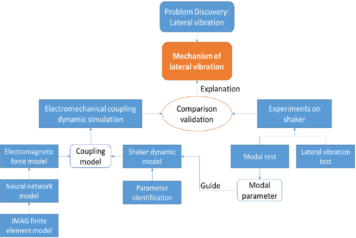
Block diagram of the proposed research.
Vibration experiment of the electrodynamic shaker
Vibration test and fault diagnose based on vibration signal are commonly used by researchers.25,26 As the method proposed in Glowacz et al. 25 and Caesarendra et al. 26 cannot obtaining system’s natural frequency, modal shape and transfer function, an experiment is carried out to getting the vertical and lateral acceleration transfer characteristics of the electrodynamic shaker while the test piece is eccentrically arranged. The test settings and measurement point arrangements are shown in Figures 2 and 3. The test piece, a steel plate of 82 kg, is fixed off-center 0.7 m on the additional table. A sinusoidal sweeping frequency signal (2–150 Hz) lasting 100s is generated by the signal generator and amplified by the power amplifier to drive the electrodynamic shaker. The driving current of the moving coil is measured by a pair of clamp ammeters, and several three-way accelerometers are installed on the additional table to test the acceleration response.

Schematic diagram of experiment layout.

Field layout of lateral vibration test.
By analyzing the self-power spectral density of drive current and cross power spectral density of driving current and the center’s acceleration signals, the transfer function in X-direction and Z-direction can be obtained respectively, as shown in Figure 4. From the Z-direction curve, four obvious peak frequencies can be found, which are 5.5 Hz, 9.5 Hz, 20.5 Hz, and 116 Hz respectively. And the highest two peak frequencies of the X-direction curve are 20.5 Hz and 113.5 Hz, corresponding to the last two frequencies of the Z-direction curve. In addition, a peak appears at 31.9Hz of non-center point’s transfer functions simultaneously. Through the method of lateral acceleration vector synthesis, the rotational vibration shape around Z-axis is found at this frequency.

Transfer function from driving current to acceleration. (a) Z-direction transfer function. (b) X-direction transfer function.
The research in this article is carried out by taking the case of eccentric load in X direction as an example. The vibration characteristics of the eccentric mass placed in Y direction can be obtained in the same way, so the process will not be repeated in the following passage.
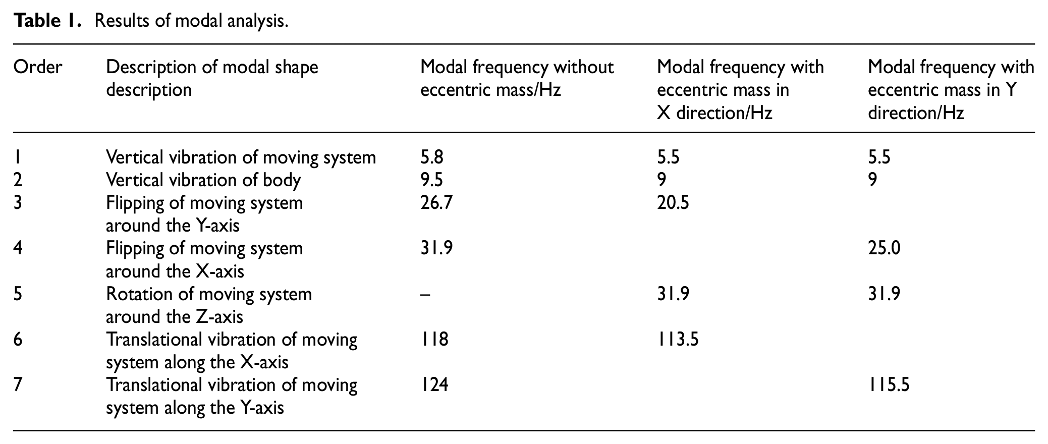
According to structural analysis of the electrodynamic shaker in the next section, the electrodynamic shaker can be regarded as a two rigid body system in the low frequency range. The system consists of one vertical DOF of the body and six DOFs of the moving system, so the modal shapes of the entire moving system can be inferred from the motion state of additional table surface. The modal shapes of electrodynamic shaker with bare table have been acquired through hammer tests in the early stage, so the modal shapes corresponding to the peak frequency of the transfer functions with eccentric mass can be deduced, as shown in Table 1. Because of the deficiency of the hammer test, the mode of moving system rotation around Z-axis was not observed in the test. It can be found that the natural frequencies of the system with eccentric mass are slightly lower than those without eccentric mass. Except for one Z-direction translation mode of the body, the remaining six modes are all rigid body modes of the additional table including the three-way translation and three-way flipping modes.
Results of modal analysis.
Electromechanical coupling dynamics modeling of electrodynamic shaker considering lateral and vertical vibration
Based on the foregoing test results and analysis, an electromechanical coupling dynamic model that reflects the lateral and vertical vibration of the electrodynamic shaker can be established. For the electromagnetic force of the moving coil, an equivalent electromagnetic force model is proposed. The electromagnetic force model comprehensively considers the vertical position, eccentricity, and current of the moving coil. For the mechanical structure part, some assumptions are introduced for model simplification firstly and then the dynamic model is established. By coupling the position of moving coil, the electromagnetic force is introduced into the dynamic model as an excitation term. With the above settings, the electromechanical coupling simulation is developed.
Structure and mechanism analysis of electrodynamic shaker
The shaker studied in this paper has a dual magnetic circuit structure and it consists of two parts: shaker body and moving system, as shown in Figure 5. The shaker body is the carrier of excitation system, which includes two excitation coils and magnetic steel. When large direct current is running in the upper and lower excitation coils, two stable magnetic field is formed and superimpose in the inner magnetic pole. Then a high magnetic density distribution area is formed, which is called working air gap. The moving coil is located in the working air gap. As alternating current is applied in the moving coil, a vertical electromagnetic force is generated to drive the entire moving system vibrating up and down.
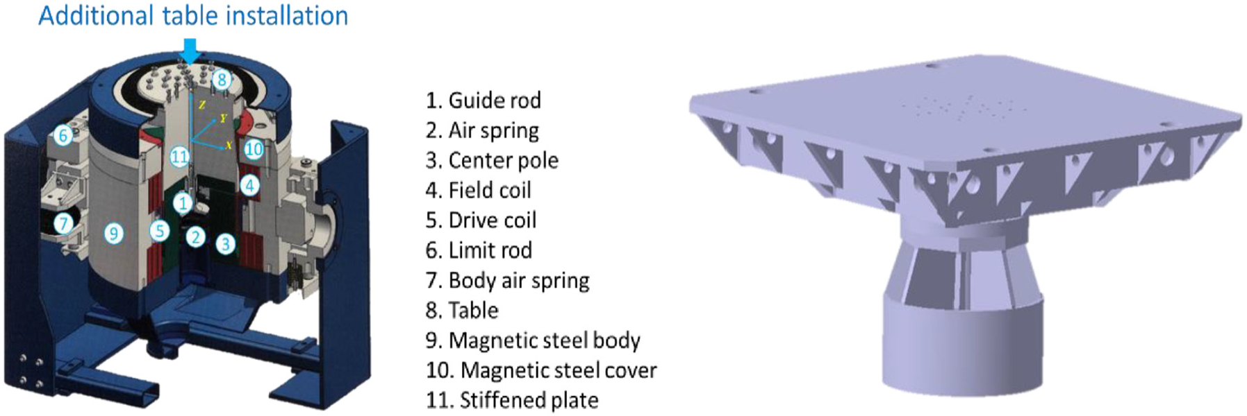
Structure Schematic diagram of the electrodynamic shaker. (a) Sectional view of electrodynamic shaker. (b) Schematic diagram of moving system structure.
The moving system includes moving coil, ribs, table and an additional table. The moving coil is integrally cast with the ribs and table, and the additional table is rigidly connected to the table with 24 bolts. From the previous finite element modal simulation of the moving system, it can be found that the frequency of first-order flexible mode is above 220 Hz, which is beyond the frequency range studied in this article. The body with a large mass is supported on two rigid stands by springs, and four rigid limit rods are used to restrict its lateral movement, so the body has only vertical translational DOF. The electrodynamic shaker studied in this article is used to reproduce the vibration environment of vehicle components aroused by road roughness. It is researched that the power spectral density distribution of road roughness decreases exponentially with the spatial frequency, of which the highest spatial frequency commonly used is 2.83 cycle/m. 27 So the frequency of the shaker model is limited below 130 Hz considering the speed and pavement conditions extending. In this low frequency range, the mechanical structure of the shaker can be regarded as a two rigid body system with one vertical translational DOF of the body and six DOFs of the moving system.
Description of flexible connection: the body is supported on two rigid stands, and the stands are fixed to the ground. Two air springs and two helical springs (hereinafter, the body springs) at each side stand provide the only flexibility to the body. There are two elastic connections between the moving system and the body. The first is the air spring under the center of the rib, which provides the vertical flexibility of the moving system. It is called suspension spring usually. It also integrates a vertical guide rod that can improve the lateral translation stiffness of the moving system. The second place is four steel leaf springs arranged around the table symmetrically, which is used to suppress the lateral vibration and torsional vibration around the Z-axis of the moving system. In addition, four air springs are installed under the corners of the additional table on rigid stands, which are called table-springs for short bellow.
Equivalent model of electromagnetic force considering moving coil eccentricity
From the analysis of electromagnetic mechanism of the electrodynamic shaker, it is known that the magnetic density distribution is not uniform in the working air gap, and its direction is not perpendicular to the magnetic pole everywhere. The moving coil’s eccentricity, aroused by the translational and flipping vibration of the moving system, will cause additional radial electromagnetic forces. When the moving coil is working at the modal frequency of the mechanical system, a small radial electromagnetic force may induce severe lateral vibration, which will further worsen the eccentricity of moving coil in turn and magnify the equivalent lateral electromagnetic force. Therefore, there is a position coupling relationship between the eccentricity of moving coil and transverse electromagnetic force, and the influence of the eccentricity must be considered in the calculating of equivalent electromagnetic force. In addition, according to Ampere’s rule, the moving coil current is another major factor, which determines the magnitude of the electromagnetic force. At the same time, the magnetic field generated by the moving coil current will also affect the excitation magnetic field. With the change of vertical position and current of the moving coil, the magnetic fields of it should be superimposed with the excitation magnetic field, which will affect the magnetic density distribution in the working air gap, and then affect the output of the electromagnetic force.
According to the structure of the actual electrodynamic shaker, five factors including moving coil current I, vertical position z, flipping angle α, radial translational eccentric direction θ and distance d are selected as variables, and an electromagnetic finite element model is established in JMAG. Among them, the material of magnetic structures is defined as No. 10 steel, and the material of the moving coil and the excitation coil is set as copper. The inner magnetic pole is provided with eight grooves in the circumferential direction to facilitate the assembly of the moving coil. The electromagnetic finite element model is shown in the Figure 6.
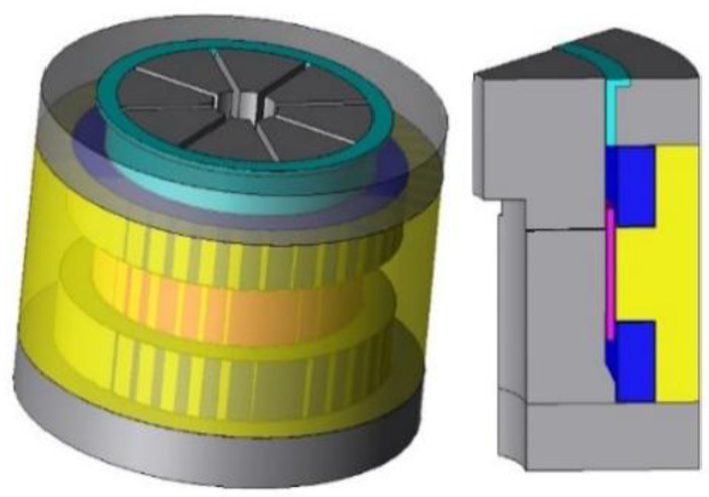
Electromagnetic finite element model.
As the electromagnetic force calculation in the finite element model takes a long time, the results cannot be loaded in the electromechanical coupling model. Therefore, 81 sets of orthogonal test in finite element model are performed on the five factors above, and the simulation results are fitted with a neural network to obtain an equivalent electromagnetic force model. Among them, the ranges of values of 5 factors are as follows: −200A ≤I≤ 200A, –38 mm ≤z≤ 38 mm, 0°≤α≤ 0.65°, –90°≤θ≤ 90°, 0 mm ≤d≤ 2 mm. The coordinate system xyz is set at the original centroid of the moving coil, of which the x axis is regarded as the flipping axis, as shown in Figure 7(a). When the moving coil rotates α degrees anti-clockwise, the moving coil after the rotation is depicted with solid line in Figure 7(b). At the same time, if the moving coil has a translational movement d along the θ angle direction, its projection diagram is shown in Figure 8. It can be seen that the range of d is related to α and θ. The constraint relationship is written as.

where f is the limit of the moving coil radial translation.

Diagram of moving coil eccentricity. (a) Schematic diagram of non-eccentric structure (b) Flipping eccentricity diagram of moving coil.

Projection diagram of moving coil.
Based on the above settings, nine levels are selected to design orthogonal tests for each factor and 81 orthogonal tests are designed by SPSS software. The values of each parameter’s levels are shown in Table 2.
Factor levels in orthogonal test.

According to 81 orthogonal simulation tests, the equivalent electromagnetic forces fx, fy, fz, and torques tx, ty, tz on the moving coil are given. These sample data is fitted by BP neural network method, which is shown in Figure 9. The input layer includes five neurons, which are I, z, α, θ, and d. In order to improve the fitting accuracy of the electromagnetic force and torque, the values of fx, fy, fz, tx, ty, tz are calculated respectively, that is, the output layer of the network includes only one neuron. The hidden layer contains 11 neurons according to the Kolmogorov’s theorem. The training algorithm uses LM optimization algorithm. Eight groups are selected as the test group randomly from the 81 simulation results and the remaining 73 are the initial training group. For the purpose of improving the generalization ability of the network, the initial training sample is expanded to 300 by two-dimensional spline interpolation. 22

Neural network structure.
From the calculation results, it can be seen that when moving coil has a flipping eccentricity about the x-axis, the electromagnetic force fy and the electromagnetic moment tx are relatively large, and the electromagnetic force changes significantly with I, z, and α. The Figure 10(a–c) show the change trend of fy, fz, and tx with z and α when I = −200A. The Figure 10(d–f) show the change trend of fy, fz, and tx with z and I when α = −0.32°. The Figure 10(d–f) show the change trend of fy, fz, and tx with α and I when z = +25 mm.

The trend of electromagnetic forces with I, α, and z. (a) The trend of fy with α and z (b) The trend of fz with α and z (c) The trend of tx with α and z (d) The trend of fy with I and z (e) The trend of fz with I and z (f) The trend of tx with I and z (g) The trend of fy with I and α (h) The trend of fz with I and α (i) The trend of tx with I and α.
Low-frequency dynamic model considering lateral vibration
The following assumptions are introduced according to the foregoing analysis:
Assuming that the shaker is a time-invariant system, and the values of all the parameters are constant during the operation.
Two rigid body: the moving system and the body.
Elastic connection: The flexible connections are all described with three-way equivalent translational stiffness and damping respectively, as shown in Table 3. The equivalent vertical stiffness of the body springs is expressed as kbz. The vertical stiffness of the suspension spring is expressed as ksz. The horizontal constraint of that position is created by both the air spring and the guide rod as expressed by ksx/ksy in equivalent stiffness. The radial, tangential, and vertical stiffness of the steel leaf spring are represented by ka, kb, and kc. Considering the difference between the steel leaf springs in X direction and Y direction, u and v are added in the subscripts separately. The three-way equivalent stiffness of the air spring between the additional table and the ground is represented by ktx/kty/ktz respectively. In the same way, the corresponding damping parameters can be gotten by latter c with corresponding angle labels.
Seven degrees of freedom.
Equivalent electromagnetic force: The distributed electromagnetic force of the moving coil in the excitation magnetic field is expressed by the equivalent three-way electromagnetic forces and torques
The contact stiffness at the center guide rod of the actual structure may cause friction. Here, the guide bar is considered to be smooth and the friction is ignored since the model is mainly used to analyze the lateral vibration.
Definition of parameters.

The Cartesian coordinate system is established at the centroid of the moving system with bare table. According to Newton Law, the dynamic equation of the electrodynamic shaker can be derived, as shown in Appendix.
It can be found that there are many coupling terms and high-order terms of displacement in the dynamic equations, which is hard to simplify and calculate. In this article, a multi-body dynamic model of the electrodynamic shaker is developed in MSC.ADAMS software, which is equivalent to the dynamic equations. Taking actual geometry and mass distribution into account, bushings with three-way translational stiffness and damping are arranged at corresponding locations, and the parameters of equivalent stiffness and damping above are applied. A six-component force including three-way force and three-way torque is set at the center of the moving coil. At the same time, the displacement and Euler angle

Schematic diagram of ADAMS model.
ADAMS model parameters.

Electromechanical coupling model
The electromechanical coupling model of the electrodynamic shaker is established with the combination of the electromagnetic force model and the structural dynamic model, as shown in Figure 12. In the figure, the Force Model is the equivalent electromagnetic force model mentioned above. The input variables of the model include the current I, the vertical position z, the eccentric state variables α, θ, and d. The transfer relationship between the above input position variables and the outputs of the dynamic model in the coordinate XYZ, which are the displacement
Similarly, the output electromagnetic force of the Force Model can be converted to the inputs of the dynamic model as:

Electromechanical coupling model.
The co-simulation of above coupling model is implemented in MATLAB SIMULINK. Firstly, shaker dynamic model is developed in the ADAMS software. Then the input and output variables in the co-simulation are here defined, including six input force variables and five output position variables. Finally, a simulation interface is exported through the Control module in ADAMS, and then imported into SIMULINK for the coupling calculation. In the meanwhile, the electromagnetic force model is also applied together. Through this method, the acceleration response of the additional table is obtained for the further analysis of transfer characteristics.
Identification of stiffness and damping parameters
There are many equivalent stiffness and damping parameters in the dynamic model of the electrodynamic shaker. Each parameter corresponds to a designed elastic constraint of the electrodynamic shaker. Therefore, the equivalent stiffness parameters is estimated by theoretical formulas firstly. However, the estimated stiffness values may have difference from the actual values to some degree and the damping parameters are difficult to estimate theoretically. Then the parameter identification base on optimization method is adopted for the accuracy.
Estimation of stiffness parameters
For the electrodynamic shaker studied in this article, there are mainly two types of springs. One is the air spring and the other is the steel leaf spring.
A same kind of bellows type air spring is used at the table spring and center spring, and the calculation formula of the vertical equivalent stiffness 30 is:

where a is shape factor,

And its transverse stiffness is written as 30

The parameters of Formula (4-6) are shown in Table 5.
Parameter values of air springs.

The four steel leaf springs are cantilever beam structures. The axial tension and compression stiffness and the bending stiffness caused by translating can be approximately calculated according to mechanics of material.

where E is the Young’s modulus, S is the cross-sectional area of the steel leaf spring, l is the effective length of the steel leaf spring.
In addition, the center rod’s contact stiffness can be derived from Hertz contact theory. With the combination of guide rod and suspension spring’s lateral stiffness, the equivalent values of the lateral stiffness ksx, ksy is derived. Similarly, the equivalent stiffness kbz can be roughly estimated.
Through the above calculations, the stiffness values is shown in Table 6, which can guide the optimization in the next section.
Estimated values of stiffness parameters.

Identification of stiffness and damping parameters
As the errors exist between the estimated values and actual values, the system modal frequencies are different from experimental results. It is found that the shaker’s dynamic equation cannot be completely decoupled. One modal frequency is associated with multiple stiffness parameters. Therefore, it is difficult to adjust the parameters artificially to fit the modal frequencies with the experimental values. Hence, optimization method of the stiffness parameters is adopted. The sensitivity of each stiffness is analyzed firstly and seven main stiffness parameters are selected: {kbz, ksx, ksy, ktx/kty, ktz/ksz, kua, kva}. For each stiffness parameter, five levels {–γ, –1, 0, 1, γ} are defined and encoded, as shown in Table 7. The value of γ is determined as follows.

With p number of optimization factors, and
Coding schedule of stiffness parameters.

A total of 143 experiments are performed, and the regression functions between each modal frequency and key parameters can be obtained with the quadratic regression method.

where xj is the optimized factor, b0, bj, bjk, bjj are the coefficients correspondingly.
With the regression functions, the accurate values of stiffness parameters are identified by genetic algorithm, as listed in Table 8. Similarly, the damping parameters can be acquired in the same way. The peaks of the transfer functions in Section 2 are extracted and taken as the optimization objectives. The identified stiffness and damping parameter values are listed in Table 8.
Identified stiffness and damping values.

Lateral vibration comparison of simulation and experiment
From the electrodynamic shaker model with the modified values of the parameters above, the simulated modal frequencies are very close to the experimental results, as shown in Table 9.
Modal frequency comparison between simulation and experiment.

The comparison of the transfer curves is depicted in Figure 13. It can be found that the simulation results agree well with the experiment ones. The two peaks of simulation is related to the flipping mode and translational mode of the moving system, which coincides with the experimental result. Therefore, it can be inferred that by considering the lateral translation and flipping DOFs of the moving system during the modelling, the lateral vibration characteristic of the electrodynamic shaker can be accurately described. The lateral vibration response is evaluated by this model below.
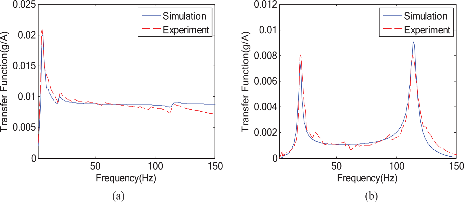
Transfer function comparison of simulation and experiment. (a) Z-direction transfer function. (b) X-direction transfer function.
A constant frequency vibration simulation of the electrodynamic shaker with an off-center load is performed in this article. The amplification of table center’s vertical vibration acceleration is set 1 g. 20 Hz and 115 Hz, the two resonance frequencies are chosen as testing frequencies. Due to the influence of flipping vibration mode, the lateral vibration amplitude at 20 Hz in the simulation reaches over 0.5 g, and the lateral vibration ratio is 48.7%, which is closed to the experimental result 51.9%. And the lateral vibration ratio at 115 Hz in the simulation is 101.7%, which is a little higher than the test result 99.6%. The acceleration data in time domain is shown in Figures 14 and 15.
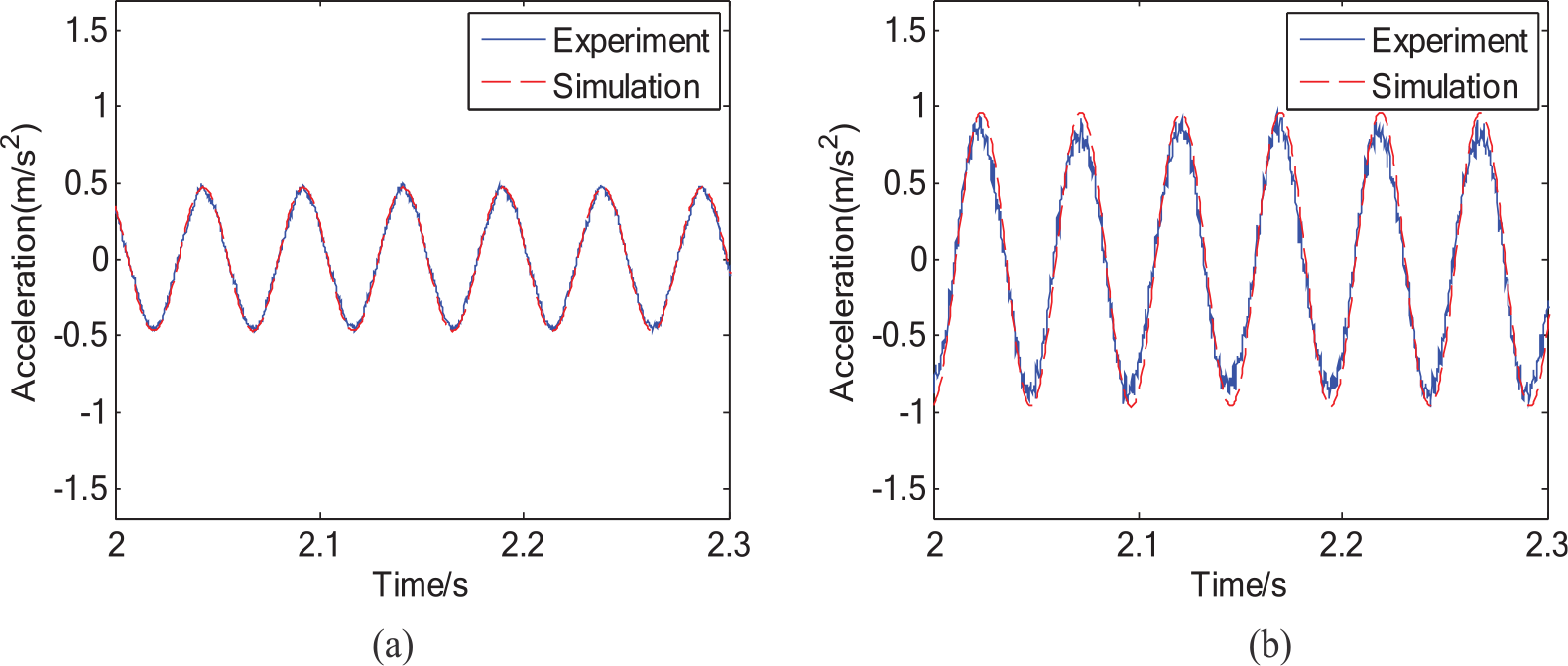
Acceleration comparison at 20 Hz in time domain. (a) Lateral acceleration. (b) Vertical acceleration.

Acceleration comparison at 115 Hz in time domain. (a) Lateral acceleration. (b) Vertical acceleration.
From the simulated electromagnetic force, it can be found that the amplitude of the vertical electromagnetic force is 6405 N and the amplitude of the lateral electromagnetic force is 3.2 N, which is only 0.05% of the vertical force. In order to further explore the main source of lateral vibration, this article performs a simulation that applies only vertical electromagnetic force, sets the two-way lateral electromagnetic force and three-way electromagnetic torque to 0, and observes the transfer function and lateral vibration ratio. The result has little change with only vertical force. It tells that the lateral vibration is mainly caused by the eccentricity of the vertical electromagnetic force, and the influence of the lateral electromagnetic force is relatively small.
Conclusion
Through the test on the electrodynamic shaker, the transverse vibration problem is revealed. Then an electromechanical coupling dynamic model of the electrodynamic shaker is developed and verified through experiment. The conclusions can be drawn as follows: (1) Severe lateral vibration is discovered at some frequencies, which is corresponding to the moving system’s flipping mode and horizon translation mode. Therefore, it is necessary considering the lateral DOFs in the modeling of shaker. (2) Taking the eccentricity of the moving system into account, an equivalent electromagnetic force model is constructed. The equivalent electromagnetic force can be calculated in real time when the moving coil moves, which lays the foundation of two-way coupling between the electromagnetic force and moving conditions. (3) The co-simulation is implemented by combining the electromagnetic force model and the shaker dynamic model. Referring to the modal test and transfer characteristic test, the coupling model is verified. The mechanism of lateral vibration is revealed through the simulation results.
The model proposed can be further used for the control research and optimization design of the electrodynamic shaker. And its research idea can be referred for modeling and analysis of abnormal vibration of electromechanical coupling systems. First of all, the modal analysis and transfer characteristic test under working condition are carried out for the preliminary understanding of abnormal vibration mechanism, which is also a prerequisite for modeling. For the coupling model, obtaining the coupling relationship of the mechanical part and the electromagnetic part and rationally simplifying of it are very important. For example, this article takes three equivalent displacement parameters and six electromagnetic forces of the moving coil as the coupling elements. For a complex finite element model, getting simulation results under all operating conditions are often time-consuming. The fitting model trained by neural network can meet the actual engineering needs of accuracy and calculation speed, providing ideas for real-time coupled simulation. The research methods proposed in this article can be applied to modeling and analysis of anomalous vibration mechanism of many electromechanical coupling systems.
Footnotes
Appendix
Dynamic equations of the electrodynamic shaker can be derived as:
where
Handling Editor: James Baldwin
Declaration of conflicting interests
The author(s) declared no potential conflicts of interest with respect to the research, authorship, and/or publication of this article.
Funding
The author(s) disclosed receipt of the following financial support for the research, authorship, and/or publication of this article: This work is financially supported by the National Key R&D Programme of China (grant number: 2017YFB0103103) and the National Natural Science Foundation of China (grant number: 51875410).