
Abstract
In order to study the influence of blade outlet cutting width on hydrodynamic excitation noise of the centrifugal pump with low specific speed, five schemes are used to perform V-shaped cutting on the outlet of the impeller blade are studied in this study. Based on Lighthill acoustic analogy, combining computational fluid dynamics and computational acoustics, RNG k-ε turbulence model is used to calculate internal unsteady flow field of the centrifugal pump, and the acoustic solution is based on the flow field calculation. The results show that the pressure pulsation can reflect the sound pressure level to a certain extent; proper cutting of the blade outlet can improve the flow state of the rear cavity of the centrifugal pump and make the flow uniform; the V-shaped cutting of the blade outlet also can reduce the dynamic and static interference between the impeller outlet and the volute tongue, effectively reducing the sound pressure level of the internal sound field, when the blade outlet cutting width is a/b2 = 33.33%, the inlet sound pressure level and the outlet sound pressure level are decreased by 4.8% and 7.2%, respectively. In terms of internal sound field, the sound pressure level at the outlet of the pump is obviously higher than that at the inlet.
Introduction
In recent years, centrifugal pumps have been widely used in various industries. Centrifugal pumps are often accompanied by strong noise when they are running. There are many sources of internal noise in centrifugal pumps, mainly including mechanical vibration noise and hydrodynamic noise. 1 Mechanical vibration noise is mainly caused by machining errors. With the improvement of machining accuracy, it has been continuously resolved. The hydraulically induced vibration and noise are mainly caused by the internal flow structure of centrifugal pump, and studying the mechanism characteristics of the internal flow and hydrodynamic noise has become a current research hotspot.
At present, scholars at home and abroad have made a lot of research and analysis on the hydrodynamic noise of centrifugal pump through theoretical analysis, numerical calculation and experiment. 2 Liu et al. 3 reduced the fan noise by changing the width of the volute. Centrifugal fans and centrifugal pumps have many similarities, so in later studies, many scholars took the volute as the main research object.4–7 In order to study the main location of centrifugal pump noise under rotating stall, Zhou et al. 8 tested it, and the results showed that the most serious place of pressure pulsation under rotating stall was located at the volute tongue of centrifugal pump. After that, Sundström et al. 9 carried out relevant research on rotating stall and noise, the results showed that the rotating stall and surge were the key factors leading to the flow instability of noise in the centrifugal compressor at low mass flow rates. However, rotating stall and surge were easy to occur at low mass flow rate, and the occurrence of rotating stall and surge could easily lead to noise generation. Therefore, Galindo et al. 10 proposed to eliminate the noise caused by rotating stall and surge by changing the shape of blade inlet geometry. Si et al. 11 studied the interaction between centrifugal pump impeller and the volute tongue. The results showed that when the clearance ratio between impeller and tongue was 20%, the noise would be significantly reduced. Xiong et al. 12 modified the volute tongue of the centrifugal fan and found that a new arc-shaped tongue can effectively reduced the vortex intensity at the tongue, thereby reducing the noise of the centrifugal fan.
The impeller was the core component of the centrifugal pump. The blades on the impeller had a very important impact on the noise of the centrifugal pump when it was rotating. Guo et al. 13 discussed that impeller blade wrap angle, blade outlet angle and blade inlet diameter have a great influence on the hydraulic and acoustic performance of centrifugal pump. Luan et al. 14 studied the outlet width of the impeller by using the boundary element method and found that changing the outlet width of the impeller has a certain impact on performance and noise. Cheng et al. 15 analyzed the relationship between the guide vane of the nuclear main pump and the volute, it could be concluded that the location of the guide vane has a great influence on the pressure pulsation of the nuclear main pump. In order to reduce the noise of centrifugal pump, Dai et al. 16 proposed a method of tilting blade outlet. The results showed that the tilting blade could improve the overall efficiency of centrifugal pump and reduce the noise. Ma et al. 17 studied the influence of the impeller outlet diameter on the noise induced by centrifugal pump, and found that with the increase of impeller outer diameter, the amplitude of the pulsation at the blade passing frequency and its second-order harmonic frequency increased correspondingly. Yang et al. 18 proved experimentally that the main source of centrifugal pump noise was blade passing frequency. Wang et al. 19 used an indirect numerical calculation method to analyze the influence of blade number on the noise of centrifugal pump. The results showed that the sound pressure level first decreased and then increased with the increase of blade number.
Although scholars at home and abroad have made some research on the induced noise of centrifugal pump blades, the traditional method is to cut the centrifugal pump impeller including the front and rear cavity and change the impeller outlet width. The traditional method is relatively simple and has a large impact on performance. The purpose of this study is to find a more reasonable solution, which has a small impact on performance while reducing noise. Taking a single-stage single-suction pump with low specific speed as the research object, V-shaped cutting is carried out on the outlet edge of the impeller blade. The internal flow of the centrifugal pump and its mechanism of noise suppression are studied by numerical calculation and experimental methods, which provide a certain theoretical basis for the design of low-noise centrifugal pump.
Governing equation
The fluid flow in the centrifugal pump is extremely complicated. In the problem of flow acoustics, the flow field and sound field are unified. The transient flow equation of the centrifugal pump is described as the governing equation. Its equation is as follows.


Where,


Where,

In the formula,
In the actual operation of the fluid, further simplification is often required. The fluid medium in the pump is normal temperature water, which is generally considered to be incompressible, and Mach number Ma of the fluid in the pump is small. Therefore, the monopole source and the quadrupole source can be ignored. The main noise source in the pump is the dipole source. After the unsteady calculation, the pressure on the volute wall is extracted and interpolated into the acoustic software for acoustic calculation. Figure 1 is the calculation flowchart.

Calculation flowchart.
Geometric model and numerical calculation method
The calculation model is a single-stage single-suction centrifugal pump with low specific speed as the research object, and its flow rate Qd = 12.5 m3/h, head Hd = 20 m, rotational speed n = 2900 rpm, specific speed ns = 66, blade passing frequency BPF = 241.7 Hz (BPF = nz/60), axis passing frequency APF = 48.3 Hz (APF = n/60), other main geometric parameters of centrifugal pump are shown in Table 1.
Other main geometric parameters of centrifugal pump.

Figure 2 shows the three-dimensional fluid calculation domain of centrifugal pump, including inlet section, front cavity, rear cavity, impeller, volute clearance, volute and outlet section. During the calculation process, because the impeller inlet and the volute outlet may appear backflow, in order to improve the accuracy of the numerical calculation, the pump inlet and outlet are usually extended appropriately, and the extension distance is usually 4 times of the inlet and outlet pipe diameter. S1 and S2 are the sound pressure monitoring points at the inlet and outlet pipes, respectively.

Centrifugal pump three-dimensional fluid calculation domain.
Design of centrifugal pump blade outlet cutting scheme
In this study, V-shaped cutting is carried out on the outlet edge of the impeller blade, and its top angle is 60°, as shown in Figure 3. The cutting scheme of the impeller blade outlet is shown in Table 2. The maximum cutting amount △a is selected 100% in this study (△a is the ratio of blade outlet cutting width a to blade outlet width b2, that is, △a = a/b2). Figure 4 shows the three-dimensional structure diagram of the impeller under different schemes.

Centrifugal pump V-shaped cutting.
Impeller cutting scheme.


Three-dimensional structure diagram of the impeller: (a) original model, (b) scheme 1, (c) scheme 2, (d) scheme 3, (e) scheme 4, and (f) scheme 5.
Grid generation and validation
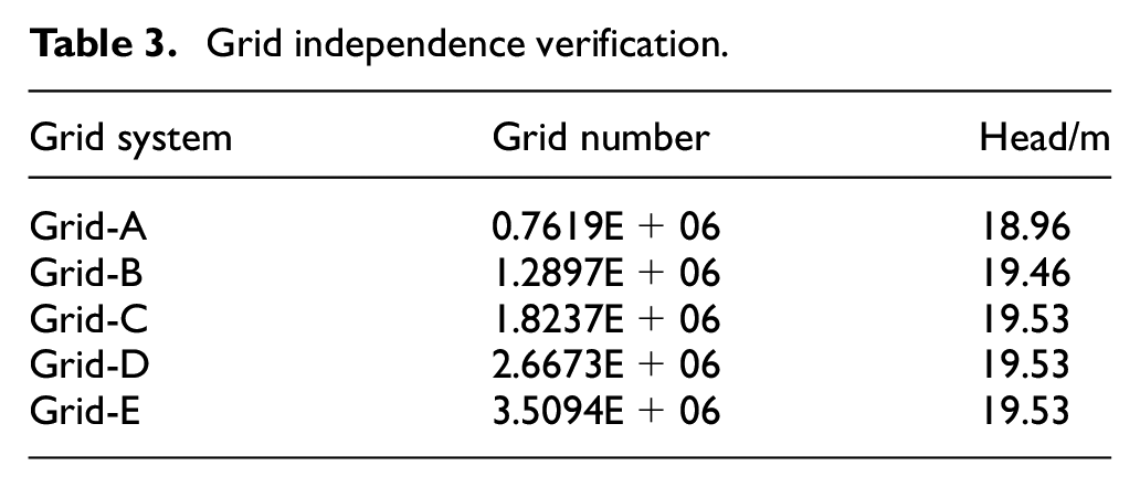
Because the structure of the centrifugal pump increases the complexity of the flow, an unstructured grid generation with strong adaptability is adopted. The quality and quantity of the grid have a very important impact on CFD calculation. The volute tongue and the blade inlet edge, which are in close contact with the fluid, need to be properly refined, as shown in Figure 5. Before analyzing the grid independence, ensure that the y+ value of the grid meets the requirements of the corresponding turbulence model, so as to ensure the practical significance of the analysis results of the independence, different turbulence models have different requirements for the y+ value of the grid, Figure 6 is the y+ distribution diagram of pump surface, it can be seen from the figure that the y+ value of impeller and volute surface are mainly concentrated in the range of 50∼150 and 20∼70, which fully meet the requirements of the RNG k-ε model. So it is verified for grid independence. Table 3 reflects the results of grid independence verification, and the total number of grid is finally determined to be 2.6673E+06.

Grid generation.

y+ Distribution of surface.
Grid independence verification.
Numerical calculation method
In this study, ANSYS CFX software is used to calculate the whole flow field. RNG k-ε is selected as turbulence model, and the standard wall function is used for the near-wall treatment. The medium is normal water and the density is assumed to be constant and incompressible. Inlet condition is set as pressure inlet, outlet condition is set as mass flow rate outlet, impeller is set as rotation domain, and others are set as static domain. The wall surface is set as the non-slip boundary condition, the SIMPLE algorithm is used for steady calculation, and the interface is set as the frozen rotor interface. After the steady calculation is completed, the unsteady calculation is carried out. The time step is set as 1.724E-04s, that is, the impeller rotates 3° in each time step. The time step can better observe the change of the flow field with time. The interface between rotor and stator is set as the transient rotor stator. After the flow stabilizes, the pressure pulsation on the volute surface is output, 20 and the data under 4 cycles are saved as the basis of acoustic calculation.
By the unsteady output of the pulsation on the volute, the sound source of the volute dipole is obtained by importing it into the acoustic software LMS Virtual. Lab. Before importing acoustics software, the acoustic grid is firstly divided. In this study, by using acoustic boundary element method, the volute wall is defined as volute dipole sound source boundary, and the sound absorption boundary conditions are adopted at the inlet and outlet. After setting the boundary conditions, acoustic software is used to solve the internal sound field of the centrifugal pump.
Experimental verification
In order to verify its correctness, a closed test bench is built for testing. Figure 7 shows the test bench. The closed test bench is mainly composed of liquid storage tank, acquisition instrument, flow meter, centrifugal pump, inlet and outlet pressure sensor, torque power meter and hydrophone. The flow rate of the centrifugal pump can be measured by the electromagnetic flow meter installed in the pump outlet pipeline, the accuracy of the flow meter is ±0.3%, and the power can be measured by the torque power meter installed in the inlet pipeline with an accuracy of ±0.25% FS. The centrifugal pump head can be calculated by the pressure sensor installed at the pump inlet and outlet with an accuracy of ±0.25%. An intelligent electrical parameter hydrophone is installed at the pump outlet to measure the outlet hydrodynamic noise. The measuring position of the hydrophone is consistent with that of the monitoring point calculated by the sound field, the intelligent electrical parameter model is RHC-10, with a frequency range of 0.02∼100 kHz and a sound pressure sensitivity of −206 dB.

Test system.
Figure 8 shows the comparison between numerical calculation and test of the external characteristics of centrifugal pump with low specific speed. The operating conditions are 0.6Qd, 0.8Qd, 1.0Qd, 1.2Qd, 1.4Qd. As can be seen from the figure, the curve variation trends of the two are the same, and the calculated values of head and efficiency are in good agreement with the test values. Under the condition of small flow rate, there is a great difference between head and efficiency, with the maximum relative error of 4.7%. With the increase of flow rate, the error of the two becomes smaller and smaller. Therefore, the calculation results can have a certain reliability for the subsequent acoustic calculation.

Comparison of hydraulic performance calculation and test of the original model pump.
The sound pressure level of the volute outlet field calculated by the original model and scheme 2 are compared with the experimental data at blade passing frequency, and the results are shown in Figure 9. As can be seen from Figure 9, the numerical calculation and experimental values of the original model and scheme 2 have a good curve trend, and the sound pressure obtained from the test is higher than the calculated sound pressure, this is because the environmental noise has a great impact on it, but the error is within 10%. Therefore, it is feasible to calculate the noise of centrifugal pump based on boundary element method. The sound pressure level at the outlet of the original model first decreases and then increases with the increase of the flow rate, reaching the minimum at the design flow rate of 1.0 Qd, while the sound pressure level at the outlet under the scheme 2 reaches the minimum under the condition of 0.8 Qd.

The calculation and test comparison of outlet sound pressure level of original model and scheme 2 at blade passing frequency under different working conditions.
Analysis of calculation results
Flow field calculation
Figure 10 reflects the performance curves of centrifugal pump under different schemes. It can be seen from Figure 10(a) that the head of each scheme decreases to some extent compared with the original model. Scheme 1, scheme 2, scheme 3, and scheme 4 does not decrease significantly, all within 5%, but scheme 5 shows obvious decline, and the maximum reduction has reached 9%. It can be seen from Figure 10(b) that by cutting the outlet edge of the impeller blade, except for scheme 5, the head and efficiency of other schemes are not significantly different from the original model. This is because the cutting area of impeller outlet in other schemes is small, so the flow loss is small, which will not have a great impact on the total efficiency of centrifugal pump. However, the cutting area of scheme 5 is larger, which will have a serious impact on the working surface of the blade, so that the head and efficiency decrease significantly.

Performance curves of centrifugal pump: (a) head curves and (b) efficiency curves.
Figure 11 shows the comparison diagram of turbulence eddy dissipation distribution of centrifugal pumps under different schemes. As can be seen from the figure, the turbulence dissipation of the original model and scheme 1 at the outlet of the impeller has no obvious change, while the turbulence dissipation in the impeller of scheme 2, scheme 3, scheme 4, and scheme 5 is gradually increasing, which are stronger than that of the original model and scheme 1. This makes the energy loss of the blade after cutting larger than that of the original model impeller, which makes the hydraulic performance of the impeller centrifugal pump after cutting lower, and the hydraulic performance of the centrifugal pump gradually decreases with the increase of blade outlet cutting width.

Comparative diagram of turbulence eddy dissipation distribution of centrifugal pump: (a) original model, (b) scheme 1, (c) scheme 2, (d) scheme 3, (e) scheme 4, and (f) scheme 5.
In unsteady calculation, it is necessary to monitor at the tongue, and the pressure pulsation can reflect the sound pressure level to a certain extent. When analyzing the pressure fluctuation data, the time-domain and frequency-domain analysis are generally used for research. The time-domain analysis method directly analyzes the time-domain signal, and the frequency-domain analysis method transforms the original time-domain signal into a more intuitive frequency-domain signal into Fourier transform. In order to eliminate the influence of the monitoring point itself on it, it is usually necessary to conduct dimensionless transformation and define the pressure coefficient Cp as

where,
Figure 12 shows the time-domain analysis results of the original model pump at the tongue of different flow rates. As shown in the dashed line in Figure 12, the pressure fluctuation at the volute tongue changes periodically, indicating that the unsteady calculation has reached a steady state 21 and can be used as a follow-up calculation. It can also be seen that the pressure pulsation fluctuation first decreases and then increases with the increase of the flow rate, and the pressure pulsation fluctuation reaches the minimum under the design flow rate, that is, the pressure fluctuation under the design flow rate is smaller than that under non-design operating conditions. Under different working conditions, the pressure pulsation fluctuation has obvious changes in different periods. As shown in reference, 22 a larger pressure fluctuation will be generated when the blade sweeps through the volute tongue, that is, when the blade passes through the tongue, it will be affected by the “wake-jet” of the impeller, resulting in local pressure rising and larger pressure fluctuation.

Time-domain change characteristics of the original model pump.
Figure 13 shows the analysis results of frequency-domain at the tongue of the pump under different schemes. As shown in Figure 13, the fluctuation of monitoring point is the smallest under scheme 2, followed by scheme 3 and scheme 4. It can be seen from the frequency-domain diagram that the pulsation amplitude first decreases and then increases with the increasing of cutting width. The peak values are mainly below 2000 Hz; under each scheme, the pressure pulsation at blade passing frequency, axial passing frequency and double blade passing frequency is much larger than other frequency components. This is because when the centrifugal pump is running, the dynamic and static interference between impeller and volute tongue has an important effect on it.

Frequency-domain characteristic diagram of centrifugal pump under different schemes.
In order to further study the influence of blade outlet cutting width on its pressure pulsation, the internal flow field is compared between the original model and each scheme. Figure 14 shows axial flow field distribution of the original model and each scheme under the design condition, the strength and position of the vortex in the comparison diagram show that the strength and area of the vortex in the rear cavity of the pump under five schemes are lower than those of the original model. With the increase of the cutting width, the strength of the vortex first decrease and then increase, and reaches the optimum under scheme 2. The streamline in Figure 14 can be also seen, the flow in the rear cavity of the original model is relatively disordered, and with the increase of the cutting width, the flow field changes from disorder to evenly, and then to disorder, and the streamline under scheme 2 changes most evenly, which shows that reasonable blade cutting can effectively improve the flow state and streamline distribution of the fluid into the pump cavity, making the flow field in the rear cavity of pump more streamlined, so as to optimize the flow in the pump cavity.

Axial flow field distribution of centrifugal pump with different blade outlet cutting width: (a) original model, (b) scheme 1, (c) scheme 2, (d) scheme 3, (e) scheme 4, and (f) scheme 5.
Sound field calculation
Figure 15 is the sound pressure level cloud diagram of different schemes under the design condition at blade passing frequency. It can be seen from the figure that the places with higher sound pressure levels under different schemes all appear near the tongue, indicating that the tongue is the main part of generating noise; Sound pressure levels of all schemes are reduced to varying degrees compared to the sound pressure levels of the original model. With the increase of cutting width, the sound pressure level first decreases and then increases, the reduction effect of scheme 2 and scheme 3 are the most obvious, and especially scheme 2 is the best. This is because appropriate V-shaped cutting of the impeller blade outlet can well reduce the dynamic and static interference between the impeller outlet and volute tongue, making it more consistent with the flow characteristics. When the cutting width is larger, the larger volute clearance will increase the occurrence of vortex, and the flow disorder will increase the noise.

Cloud diagrams of sound pressure levels of different schemes under design condition of blade passing frequency: (a) original model, (b) scheme 1, (c) scheme 2, (d) scheme 3, (e) scheme 4, and (f) scheme 5.
Acoustic software is used to calculate the sound pressure level distribution of the inlet and outlet monitoring points. The grid data is transferred to the sound field data through Fourier transform, and the frequency-domain distribution of the sound pressure at the inlet and outlet monitoring points are obtained. Figure 16 shows the frequency spectrum of the sound pressure levels at inlet and outlet monitoring points of the centrifugal pump under different schemes. As can be seen from the figure, blade passing frequency noise is dominate, and the sound pressure level gradually decreases with the increase of frequency; Under different schemes, the sound pressure at the pump outlet is greater than the pump inlet. Except for scheme 1 and scheme 5, the sound pressure levels of the other three schemes at blade passing frequency are all lower than those of the original model. In scheme 2, at the blade passing frequency, the outlet sound pressure level decreases by 7 dB, with a decrease of 4.8%, and the inlet sound pressure level decreases by 10 dB, with a decrease of 7.2%. In scheme 3 and scheme 4, both the inlet and outlet sound pressure level all decrease by 5 dB at the blade passing frequency, with a decrease of 3.5% and 3.6%. This shows that the cutting width of the outlet edge of the impeller blade has a great influence on the reduction of noise.

Frequency spectrum of inlet and outlet sound pressure levels of the centrifugal pump under design condition and different schemes: (a) original model, (b) scheme 1, (d) scheme 2, (c) scheme 3, (f) scheme 4, and (e) scheme 5.
Conclusion
In this study, a low specific speed centrifugal pump with a specific speed of 66 is numerically calculated, and the influence of blade outlet cutting width on the noise of the centrifugal pump is analyzed from the aspects of pressure pulsation, internal flow field characteristics and sound field characteristics. The main conclusions are as follows:
The pressure pulsation can reflect the sound pressure level to a certain extent, and the pressure pulsation fluctuation is the smallest under the design condition; Different blade outlet cutting width has a great influence on the pressure distribution of the of the volute tongue of the centrifugal pump, there is an optimal blade outlet cutting width to minimize pressure fluctuation.
The blade outlet cutting width has a great influence on the vortex in the rear cavity of the centrifugal pump, when the blade outlet cutting width of the centrifugal pump is a/b2= 16.67%∼50%, the vortex changes evenly.
Cutting the blade outlet edge can weaken the dynamic and static interference between the impeller outlet and the volute tongue, effectively reducing the sound pressure level of the internal sound field; the internal sound field shows that the outlet sound source is larger than the inlet sound source.
There is an optimal value for the blade outlet cutting width of the centrifugal pump to reduce the sound field in the centrifugal pump, When the blade outlet cutting width is a/b2 = 33.33%, the reduction of sound pressure level is the most obvious, and the head and efficiency loss are within 1%.
Footnotes
Handling Editor: James Baldwin
Declaration of conflicting interests
The author(s) declared no potential conflicts of interest with respect to the research, authorship, and/or publication of this article.
Funding
The author(s) disclosed receipt of the following financial support for the research, authorship, and/or publication of this article: This work is supported by the Chinese National Natural Science Foundation (no. 51469013).