
Abstract
The main purpose of this study is to investigate the influence of tool geometry (cutting edge angle, rake angle, and inclination angle) and to optimize tool wear and surface roughness in hard turning of AISI 1055 (52HRC) hardened steel by using TiN coated mixed ceramic inserts. The results show that the inclination angle is the major factor affecting the tool wear and the surface roughness in hard turning. With the increase in negative rake and inclination angles, the tool wear decreases, and the surface roughness increases. However, the surface roughness will decrease when the inclination angle increases to overpass a certain limit. This is a new and significant point in the research of the hard turning process. From this result, the large negative inclination angle (λ = −10°) should be applied to reduce the surface roughness and the tool wear simultaneously. With the optimal cutting tool angles in the research, the hard machining process is improved remarkably with decreases of surface roughness and tool wear 8.3% and 41.3%, respectively in comparison with the standard tool angles. And the proposed tool-post design approach brings an effective method to change the tool insert angles using standard tool-holders to improve hard or other difficult-to-cut materials turning quality.
Introduction
Hard turning is a developing technology to machine parts with high hardness (HRC value 45 and above) such as gears, shafts, bearings as well as other components for advanced industries. The hard turning presents several advantages compared with conventional grinding operations to finishing hard materials, such as more flexibility (easy to adapt to complex part contours; quick change-overs between component types; several operations performed in one set-up); higher productivity (high material removal rate); low cost (using the same lathe for soft and hard turning, low machine tool investment); more eco-friendly production (environmentally friendly metal chips; elimination of coolants in most cases). However, the big problem is that the turning of hard materials is the quality of surfaces of machined components (surface roughness) and rapid tool wear. As we known that the hard turning is very different from conventional machining and much of our knowledge and theoretical works on the conventional machining cannot be applied. 1 To optimize the hard turning process, the selection of cutting tool (tool material and geometry parameters) and cutting condition (speed, feed rate, and depth of cut) must be appropriate. For this purpose, many studies have been conducted using different computational methods in modeling and optimizing of the hard turning process such as:
Singh and Venkateswara Rao, 2 studied the effect of tool geometry (effective rake angle and nose radius) and cutting conditions (cutting speed and feed rate) on surface roughness during hard turning AISI 52100 steel (58 HRC) with mixed ceramic inserts. The authors used RSM and GA methods to build the regression function on surface roughness and optimize the machining process. The results indicated that surface roughness increases as the effective negative rake angle, feed rate increase and with the nose radius and cutting speed greater, surface roughness decreases. Neseli et al. 3 also investigated the optimization of tool geometry (rake angle, approach angle, tool nose radius) on surface roughness in turning AISI 1040 steel with Al2O3/TiC tool. The results of the research showed that the tool nose radius has the most influence on surface roughness, followed by the approach angle and back rake angle. Surface roughness (Ra) increases with an increase in the approach angle and back rake angle in the negative direction. However, when increasing the tool nose radius, the surface roughness increases. This result contradicts with common expectation. Sharma et al. 4 observed that the surface roughness was positively influenced with feed rate and it shows a negative trend with approach angle, cutting speed and depth of cut in hard turning using coated carbide insert. The study of Zerti et al. 5 used an application of Taguchi method to optimize cutting parameters (approach angle, tool nose radius, cutting speed, feed rate, and cutting depth) in order to minimize surface roughness, cutting force, and cutting power in dry turning on AISI D3 steel. The result showed that increasing the approach angle, tool nose radius will reduce surface roughness and approach angle is an insignificant contribution on the main cutting force.
In another aspect, Saglam et al. 6 compared the calculation results with the experiment when studying the effect of feed rate, rake angle, and approaching angle to cutting force components and cutting temperature in turning AISI 1040 steel harden at 40HRC with uncoated cemented carbide inserts. It was found that the difference in cutting forces is little, about 0.37%, while the temperature is 42%. Larger approach angle produces greater feed force, but less thrust force and increasing the rake angle in the positive direction, the cutting forces are decreased while the cutting temperature increases. Khellaf et al. 7 compared surface roughness in turning AISI H11 steel treated at 50 HRC between TiN coated mixed ceramic CC6050 and uncoated mixed ceramic CC650. A mathematical model relating surface roughness and machining parameters such as cutting radius, cutting speed, feed rate, and depth of cut, was developed using response surface methodology (RSM). The result showed that for the cutting conditions tested, the uncoated ceramic is better than coated ceramic in terms of surface roughness and wear resistance. An experimental study on turning hardened DF-3 tool steel (58HRC) with PVD-TiN coated mixed ceramic by Davoudinejad and Noordin, 8 found that better tool life and surface roughness was recorded with chamfered edge geometry. The hard turning of AISI52100 steel tests was conducted by Zhao et al. 9 to assess the effect of cutting edge radius on surface quality and tool wear. The result showed that increase in cutting edge radius will reduce tool wear. Vallabh et al. 10 investigated the effects of tool nose radius and cutting conditions on surface roughness in hard turning with CBN tools. Results showed that the surface roughness will decrease when the tool nose radius and cutting speed increase, and feed rate reduces. Xu et al. 11 changed tool rake surface geometry to improve the hard turning of AISI52100 hardened steel. The results show that the cutting force, cutting temperature and residual stress reduce than the flat tool. Li et al. proposed an analytical wear model considering the combined effects of abrasion and adhesion wear mechanisms, which was calculated by taking into account tool geometry, cutting parameters, and physical properties of workpiece and tool materials when turning titanium alloy Ti6Al4V. 12
By experimental research, Khamel et al. 13 modeled the relationship between output responses of the hard turning of AISI 52100 steel (60HRC) with the cutting conditions (cutting speed, feed rate and depth of cut) based on response surface methodology (RSM) coupled L27 Taguchi experimental design method. The results of the analysis of variance (ANOVA) showed that increasing cutting speed, feed rate and depth of cut reduces tool life and the cutting speed has the most influence on the tool life, while the feed rate is the main factor affecting surface roughness, the cutting forces are most affected by cutting depth, and the thrust force is the largest force among the three cutting force components. When the cutting speed increases, it leads to high cutting temperature in the shear zone and hence softening of the workpiece material, reducing of chip thickness and tool chip contact length and as a result, the surface roughness and the cutting force reduce and the interaction of the input factors is insignificant. Multi objective optimization of the performance characteristics (tool life, surface roughness, and cutting forces) based on DF and the statistical methods used in the study bring a reliable approach to model, optimize, and improve the turning process. Das et al. 14 also used RSM to investigate the effect of machining parameters such as cutting speed, feed rate, and depth of cut on surface roughness and tool wear when hard turning of AISI 4140 steel (52HRC) with coated ceramic inserts. The research showed that the interaction effect between feed and cutting depth on tool wear was found to be more significant than feed, with the contribution of 27% and 14.12%, respectively. And cutting speed up to 170 m/min, the BUE formed, then roughness increases with increase in cutting speed. Another attempt was made by Zerti et al. 15 to study the effect of machining parameters (cutting speed, cutting depth, and feed rate) on the performance characteristics (surface roughness, cutting force and power, and the material removal rate) in hard turning martensitic stainless steel (AISI 420) treated at 59HRC with the coated mixed ceramic insert (CC6050) according to the Taguchi experimental design (L25). The response surface methodology (RSM) and the artificial neural networks (ANN) approaches were applied to model output characteristics, and results showed that RSM and ANN models predicted very well experimental results. The effect of input variables (spindle speed, feeding speed, and cutting depth) on surface roughness during hard turning of AISI 1045 steel using YT5 tool investigated by Xiao et al. 16 This study confirms that the feed rate has a great influence on surface roughness compared to the other two variables. Laouissi et al. 17 also compared surface roughness, tangential cutting force, cutting power, and material removal rate (MRR) in turning of EN-GJL-250 cast iron using coated and uncoated silicon nitride ceramics. And the coated ceramic tool obtained a better surface quality and a minimum cutting force. And feed rate has the most influence on surface roughness, followed by cutting speed and cutting depth, while the cutting depth is the most influential factor on cutting force, followed by the feed rate and the cutting speed. In an experiment on the hard turning of AISI D3 steel with CC6050 and CC650 ceramic inserts. Bensouilah et al. 18 used the analysis of variance (ANOVA), the signal-to-noise ratio, and response surface methodology (RSM) to study the effects of cutting speed, feed rate, and depth of cut on the surface roughness and cutting forces. Parida and Maity, 19 used central composite design (CCD), response surface methodology (RSM), analysis of variance (ANOVA), and desirability function approach (DF) to study and optimize the effect of machining parameters (cutting speed, feed rate, depth of cut, and workpiece temperature) on flank wear and surface roughness in the hot turning of Monel-400. And the analysis showed that the mathematical modeling’s determination coefficients, R2, are 86.17% and 94.72%, respectively for surface roughness and flank wear, it is high enough to obtain reliable estimates. Bagaber and Yusoff, 20 also applied CCD, RSM, ANOVA, and DF for research of Austenitic stainless steel AISI 316 was turned with an uncoated carbide tool. The results indicated that feed rate and cutting speed are significant factors that influence surface roughness and tool wear, respectively. The surface roughness increases when cutting speed, and feed rate increase, while the tool wear increases with increasing the cutting speed, and depth of cut. And the quadratic mathematical models have the high determination coefficients R2 for power consumption, surface roughness, and tool wear. And Elmunafi et al. 21 also showed that the trend of influence of cutting condition including cutting speed and feed rate on surface roughness, cutting forces and tool life is similar between dry hard turning and under minimum quantity lubrication using castor oil.
Through the above studies on the hard turning, most authors focus on cutting conditions, there has been only little research on tool geometry including tool angle, tool nose radius and cutting edge preparation, in which the tool angle plays a very important role in the cutting process. 22 But the combined effect of tool angle factors on the simultaneous outcomes of hard turning process has not been studied properly and as we have known that the standard tool inserts used in hard turning, the tool angles were determined by the tool holder for main straight cutting edge, but only the tool nose radius corner is engaged in hard turning because of the small depth of cut. Since we need the full study of these tool angles to optimize for the hard turning process and this is the first time a paper focused on studying the combined effect of all tool angle parameters on performance characteristics included surface roughness and tool wear in hard turning. These are the most important outputs of the machining process.
Experimental procedure
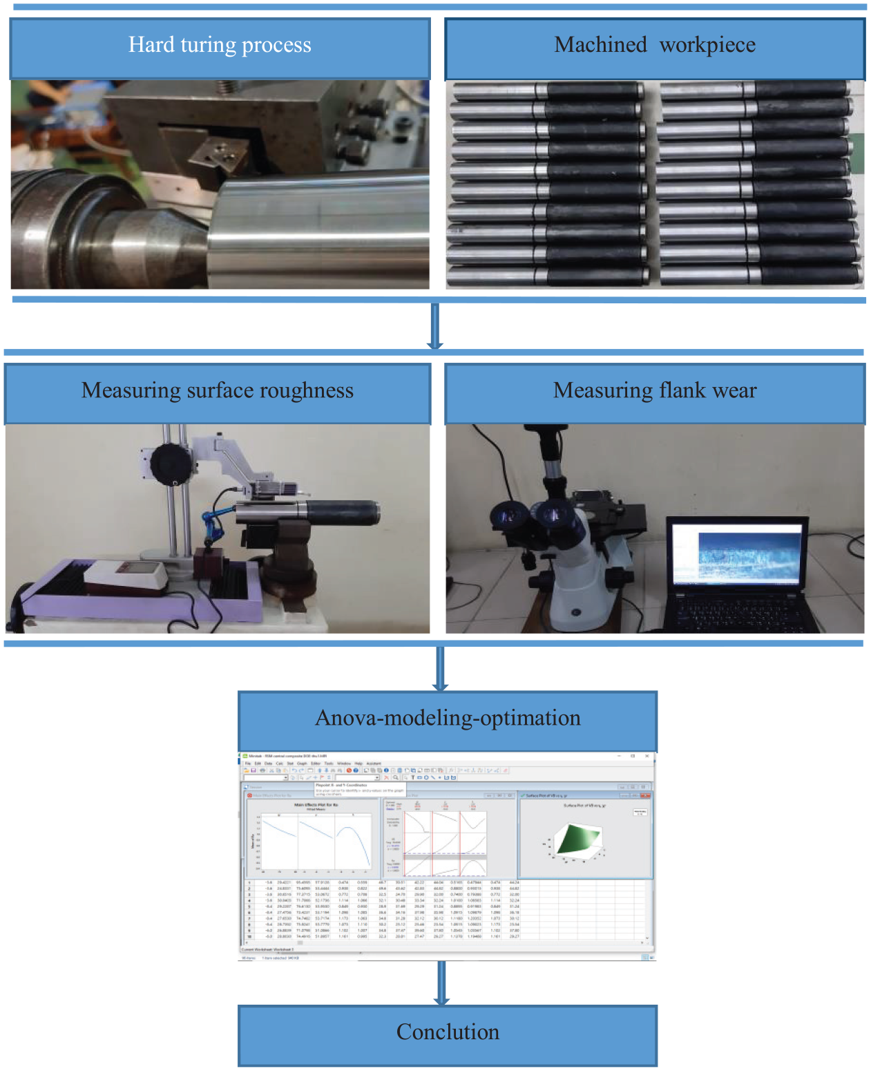
Equipment and materials
The hard turning was performed by using CNC lathe BOEHRINGER DUS-400ti and mixed ceramic inserts ((PVD-TiN) coated (70% Al2O3 and 30% TiC)) to turn the workpieces of AISI 1055 hardened steel (HRC value 52 ± 1) with (dimensions: a diameter of 53 mm, length of 130 mm as Figure 1). The cutting inserts, with the ISO designation TNGA160408S01525, were clamped on a tool holder, ISO designation PTGNR 1616H 16. The combination of the insert and the tool holder resulted in rake angle γ = –6°, cutting edge angle κr = 91°, and inclination angle λ = –6°. Inserts and tool holder from Sandvik.
Experimental setup.
Cutting condition is selected based on the tool manufacturer’s catalogue with cutting speed v = 120 m/min, depth of cut dw = 0.2 mm, feed rate f = 0.08 mm/rev.
The tool post system for changing tool angles has been designed with Solidwork software, fabricated on a 5-axis milling center DMG MORI DMU65 mono BLOCK and tested on a coordinate measuring machine (CMM) Hexagon GLOBAL Classic.
Procedure for designing the tool post system as Figure 2, step 1: positioning the insert tip in the reference plane and changing rake and inclination angles, step 2: assembling the tool holder with the insert, step 3: assembling the holder with the tool holder, step 4: finishing.

The toolpost system design process for γ = −6°, λ = −2°.
Methodology
Response Surface Design (RSM) is a collection of mathematical and statistical techniques that are useful for the modeling and analysis of problems in which a response of interest is influenced by several variables 25 and RSM coupled with Central Composite Design (CCD), desirability function (DF) optimization becomes an effective method to design experiments, develop mathematical model and optimize this response with a moderate number of experiments.
The experimental results are used to establish the quadratic mathematical model as:
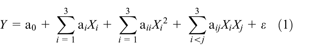
Where Y is the desired response: surface roughness, and flank wear; a0, ai, aii, and aij are constant, the coefficients of linear, quadratic and interaction terms, respectively. Xi reveals the coded variables corresponding to cutting edge angle (κr), rake angle (γ) and inclination angle (λ), and
Central Composite Design (CCD), as shown in Table 1, is the most widely used response surface design to establish the quadratic mathematical model for the response variables with center points, augmented with a group of axial points or star points. Using the axial points is an efficient way to determine the coefficients of a second-degree polynomial. 24
Experimental design based on CCD.

Results and discussion
Analysis of Variance (ANOVA) is a statistical method used to analyze and evaluate the effect of categorical factors on responses. The analysis was carried out for a level of significance of 5%, that is, for a 95% reliability level. When p-values are less than 0.05 (or 95% confidence), the obtained models are considered to be statistically significant.
The other important coefficient is the determination coefficients R2, which is defined as the ratio of the explained variation to the total variation and it is a measure of the degree of fit. When R2 approaches to unity, the better the response model fits the actual data and Table 2 shows experimental results based on CCD.
Experimental results based on central composite design.

The hard turning is a finishing or semi-finishing turning process, the depth of cut is usually small (dw = 0.1–0.2 mm), 26 since the cutting process occurred at the tool nose radius corner only and the tool nose radius acts as the main cutting edge. A change in cutting edge angle does change the cutting position on the tool nose radius as Figure 3(a) and the change of the rake and inclination angles mainly cause the change of the local inclination angle and the local rake angle respectively at given each point (each cutting edge element) of the tool nose radius cutting edge in hard turning process as Figure 3(b).

(a) Configuration in hard turning process (E.C.E is the equivalent cutting edge), 23 (b) tool geometry for a given point (each cutting edge element) of the tool nose radius cutting edge.
Surface roughness analysis
The surface roughness (Ra) was performed with a roughness meter Surftest SJ-210 Mitutoyo. The examined length is 4 mm with a cut-off of 0.8 mm and the measured values of Ra are within the range 0.279 to 1.020 µm. Surface roughness was measured three times following three generatrices positioned at 120°. The result is the average of these values for each cutting condition.
From Table 3, the inclination angle has the most influence on the surface roughness with 32.54%, followed by the rake angle and the cutting edge angle with 11.88% and 9.97%, respectively. The reason is that a change in the inclination angle does the most change in local rake and flank angles, while the surface roughness is affected by these two angles. And the quadratic λ*λ and interactive κr*λ, κr*γ terms have significant effects on the surface roughness with 31.95%, 6.6%, and 3.39%, respectively.
Analysis of variance for surface roughness Ra.

The main and interaction effect plots for the surface roughness are shown in Figure 4(a) & (b). Clearly, as the negative inclination and rake angles increase, the surface roughness increases. If the inclination angle continues to increase over a certain limit (λ = –8.1°), the surface roughness will decrease. This case can be explained that when the negative inclination and rake angles increase, leading to increasing the local negative rake angle and the local flank angle accordingly (Figure 3(b)), but the increase due to the inclination angle is the largest. As the local negative rake angle increases, an increase in the tool–chip contact length and the chip compression ratio (CCR), which causes vibration, so the surface roughness increases. The result is similar to Singh and Venkateswara Rao, 2 however, he only changed (effective) local negative rake angle by using the inserts with the different chamfered cutting edge. Conversely, increasing the local flank angle reduces the tool-workpiece contact area and the friction due to springback of the workpiece material 23 so it generates less vibration by the rubbing action of cutting tool on the workpiece surface and this improves the surface roughness. To a certain limit, the positive effect of the local flank angle is greater than the negative effect of the local negative rake angle on the surface roughness, so the surface roughness decreases. In other words, with the optimal tool angles, the tool engages the workpiece material more easily.
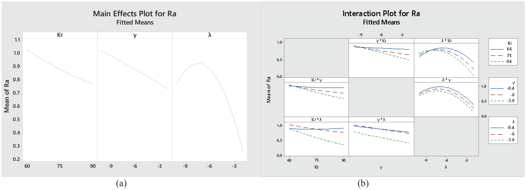
Main effects and interaction plots for surface roughness Ra
And surface roughness decreases with an increase in cutting edge angle has been presented by Sharma et al. 4 and Zerti et al., 5 however Neseli et al. 3 reported that the surface roughness and the cutting edge angle have the same trend. This difference may be due to the cutting process occurring at the tool nose radius corner or main cutting edge.
The quadratic model of response equation in terms of actual factors for surface roughness as follow:
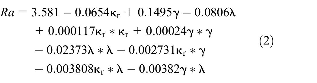
The determination coefficient R2 for the regression equation is 97.89%, it is high enough to obtain reliable estimates.
Tool wear analysis
Tool wear testing based on ISO 3685 standards, among the different forms of tool wear in this study including crater, notch and flank wears, the flank wear placed on the clearance face is the most important measure of the lifespan as it affects the surface quality of workpiece. When the flank wear of 0.3 mm achieved is often used to define the end of effective tool life in hard turning and abrasion is main wear mechanism on the relief face as showed in Figure 5, it agrees with the observations of Sudhansu et al. 14 As the small depth of cut (0.2 mm) is less than the nose radius (0.8 mm), the tool wear occurred in the tool nose radius corner only. The flank wear is measured using a biological microscope Oxion Inverso equipped with the Amscope software.

Flank wear for 17th test: γ = –6°, λ = –6°, and χr = 75°.
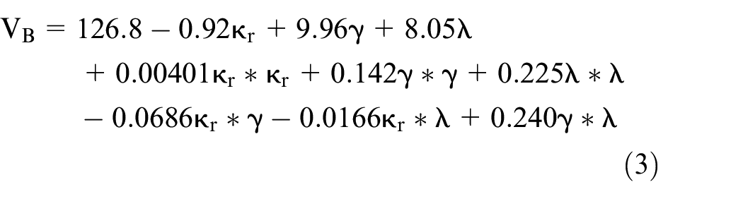
Table 4 shows the inclination angle is also the major contributor to the flank wear, accounting for 60.06%, and the rake and cutting edge angles are 23.37% and 4.20%, respectively. All other terms are insignificant.
Analysis of variance for tool wear VB.

As shown in Figure 6, the flank wear decreases when the rake and inclination angles increase in the negative direction. This case can be explained that the increase in the rake and inclination angles leads to the increase in local flank angle as it reduces the contact area and friction between flank face and machined surface due to springback of the workpiece material. The results are found to be consistent with those of Senthilkumar et al. 27 The regression equation for tool wear with R2 = 94.6, it presents that good agreement between the predicted and experimental values.

Main effect plots for flank wear VB.
From the analysis of surface roughness and tool wear, it shows that the trend of influence of tool angle parameters during hard turning on the surface roughness and the flank wear is opposite.
Comparison between experimental and predicted results
The comparison between the experimental values (measured) of Ra and VB, and those estimated by the mathematical models obtained by the RSM method is presented in Figure 7. It shows that predicted and measured values are very close to each other.

Comparison between experimental and predicted results: (a) surface roughness, (b) flank wear.
Multi-objective optimization
A desirability function approach is the widely used multi-response optimization technique, the desirability function (D) as follows:

If your goal is to maximize the response, the desirability must be assigned as follows:

If your goal is to minimize the response, the desirability must be assigned as follows:

If your goal is a target of the response, the desirability must be assigned as follows:
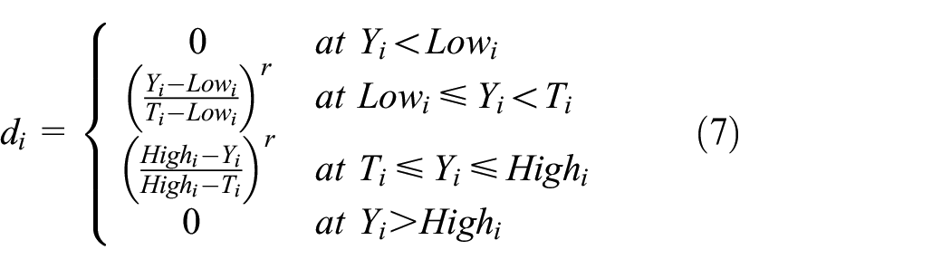
One of the main goals of this research is to find tool angle parameters in order to obtain the lowest flank wear, the desired surface roughness in the hard turning, so the equation (7) used.
Figure 8 shows the multi-objective optimization results for flank wear and surface roughness. The optimum tool angle parameters obtained in Table 5 are found to be cutting edge angle κr = 75°, rake angle γ = –6°, and inclination angle λ = –10°. And the optimized flank wear and surface roughness values from the experimental test are Ra = 0.767 µm and VB = 22.2 µm compared to the flank wear and surface roughness values obtained from the standard tool geometric parameters (κr = 91°, γ = –6°, and λ = –6°) are Ra = 0.836 µm and VB = 37.8 µm. The surface roughness and tool wear decrease 8.3% and 41.3%, respectively.

Optimization plot for simultaneous surface roughness and tool wear.
Optimization results for the flank wear and surface roughness.

Conclusion
The experimental study is focused on investigating the effect of tool geometry parameters (cutting edge angle, rake angle, and inclination angle) on the performance characteristics (surface roughness and tool wear), establishing the quadratic mathematical model and optimizing the process in finish hard turning of AISI 1055 steel hardened at 52HRC with TiN coated mixed ceramic inserts. Based on the experimental result and subsequent analysis, the main conclusions are drawn as follows:
The hard turning is a semi-finishing or finishing turning process, since only the tool nose radius corner is engaged. The change of the rake angle and the inclination angle mainly causes the change of the local inclination angle and the local rake angle, respectively at given each point (each cutting edge element) of the tool nose radius cutting edge. And the cutting edge angle has the least influence in finishing hard turning.
The inclination angle has the most influence on surface roughness with 32.54%, followed by the rake angle and the cutting edge angle with 11.88% and 9.97%, respectively. The interaction effects between the cutting edge angle with the rake and inclination angle on the surface roughness are noticed. The surface roughness increases when the negative rake, and inclination angles increase, and the cutting edge angle decreases. If the inclination angle continues to increase over a certain limit (λ = –8.1°), the surface roughness will decrease. This is a new and significant point in the study of hard turning process.
And the inclination angle is also the major factor effecting on flank wear with 60.06%, followed by the rake angle with 23.37% and the cutting edge angle with 4.2%. The results showed that the tool wear decreases with an increase in the negative rake and inclination angles.
The role of the tool insert angles is different between hard and traditional turning. With the inclination angle is the most important tool angle in the hard turning, while the rake angle has the most influence in the conventional turning.
The trend of influence of tool angle parameters on surface roughness and flank wear is opposite during hard turning.
Optimum cutting insert geometries in hard turning of AISI 1055 steel (52HRC) with coated ceramic inserts are cutting edge angle κr = 75°, rake angle γ = –6°, and inclination angle λ = –10°. With the optimum angle parameters, the hard machining process is improved with surface roughness and tool wear decreasing 8.3% and 41.3% compared to the standard tool geometry.
The proposed tool-post design approach brings an effective method to change the tool angles of inserts using standard tool-holders to improve hard or other difficult-to-cut materials turning quality.
And Response Surface Design (RSM) with Central Composite Design (CCD) and desirability function (DF) optimization integration is an effective methodology for analyzing, evaluating, and optimizing the machining process.
Footnotes
Acknowledgements
The authors would like to thank Faculty of Mechanical Engineering, Ho Chi Minh city University of Technology and Education, and Faculty of Mechanical Engineering, Ho Chi Minh city University of Technology, Vietnam for technical supports.
Handling Editor: James Baldwin
Declaration of conflicting interests
The author(s) declared no potential conflicts of interest with respect to the research, authorship, and/or publication of this article.
Funding
The author(s) received no financial support for the research, authorship, and/or publication of this article.