
Abstract
Throwing device is an important factor that directly affects the performance of chaff cutter. In this work, the dynamic analysis linked with the problem of low efficiency and residue blockage of disc knife chaff cutter is executed. Based on this perspective, the mathematical model, simulation, and testing of the material movement have been carried out. Simulations are performed in MATLAB/Simulink environment. An anemometer records the airflow velocity, which provides data for simulation analysis. The simulation results showed that during the movement along the blade, the material first performs deceleration and then accelerates; in other stages, only deceleration. And finally calculated the throwing distance. To support the presented simulations, an experimental study is conducted. The experimental results are compared with simulation results, the maximum relative error between the simulated value and the experimental value is 9.42%, which verified the correctness of the model. This research provides a theoretical basis for the structural design, parameter optimization, and matching of the chaff cutter.
Introduction
Throwing device plays a vital and significant role in forage harvester, straw crusher, kneader, and chaff cutter. It relies on the centrifugal force generated by the high-speed rotation of the throwing blade and the high-speed airflow to throw the material.
Significant work has been carried out for enhancing the performance related to the throwing device. Totten and Millier 1 used high-speed photography to study the movement and power consumption of the cutting section of green fodder straw along the throwing blade (radial) and discharge straight pipe. The material trajectories obtained are in agreement with those calculated by Kampf’s mathematical model. Based on their research, Ruiqian 2 theoretically analyzed the motion of particles on a plane blade rotating at a constant speed around the horizontal axis, obtained the differential equation of motion and its solution, discussed the influence of various parameters on the motion, but field experiment has not been done. By way of installing a synchronous straw recovery device in 2BMFJ series no-tillage straw mulching precision seeder on the original stubble land, Chen et al. 3 analyzed the dynamics of straw thrown out laterally, established a dynamic model with the correction coefficient and a parametric equation of space motion trajectory, and established a regression model with correction coefficient by using high-speed photographic experiments. Compared with field experiments, the results showed that the average straw recovery rate was 91.21%, and the ambiguity was 6.08%. Aiming at the problems of high-power consumption and easy blockage in straw-smashing back-throwing type multi-function no-tillage planter, Wu et al. 4 redesigned and analyzed the throwing pipeline, established response surface mathematical model, used Design-Expert software to optimize the influencing factors comprehensively, and established the optimization model. Compared with the experimental results, the relative error is less than 5%. This research only aims at rice straw, and further research is needed for other crop straw. Aiming at the problems of unadjustable chopped straw spreading uniformity and width after the straw smashing machine, Zhang 5 designed a straw chopper cum spreader with adjustable spreading device, and based on the designed machine, the dynamic analysis of straw smashing and throwing process was carried out, and the relationship between straw scattering characteristics and design parameters of straw smashing and throwing machine was established, which was verified by the throwing test. This study was incomplete in considering the influence factors during the experiment.
In pace with the development of computer technology, computer-aided software has also been widely used.6,7 Chen et al. 8 used CFD simulation technology to establish the airflow velocity field distribution model of the blower device of the medicago hispida harvester, and carried out validation tests under the same simulation conditions. The results showed that the experimental values and the simulation values have the same trend, the error between these is not more than 10%, which can accurately reflect the distribution law of airflow velocity field of the blower device of the medicago hispida harvester. For describing the movement characteristics of air and shredded material in the feed harvester discharge port, Świątek and Lisowski 9 and Lisowski et al. 10 used Fluent software to simulate the airflow in the nozzle. Material movement speeds were recorded by ultra-fast digital camera. The model established in this study is limited to traction feed harvesters with low throughput. To reveal the relationship between material movement law and power consumption and throwing efficiency of blade throwing device, Zhai et al. 11 established the dynamic model and ADAMS model of material movement along the throwing blade. Combining with a high-speed camera test, the optimum throwing angle range of material was obtained, which was about 60º~130º. Then, from gas-solid two-phase flow, Zhai et al.12,13 established the numerical model based on the Mixture model and Eulerian model by using Fluent software. The numerical results and high-speed camera tests showed that the numerical model can predict the conveying performance and the optimum feeding quantity of the vane-type throwing device. Also, the vibration and noise of the throwing device have been studied, and some achievements have been made.14,15 In the above studies, the particles are all spherical, which is different from the actual shape. To explore the law of airflow and material interaction in the discharging device of 9FH-40 kneading machine at different working speeds, Zhang et al. 16 utilized the CFD-DEM method to simulate the airflow and material interaction process. The results showed that the higher the rotational speed, the greater the air velocity and material coupling force, and the stronger the fluctuation. The coupling force in the material inlet area is less affected by the rotational speed, while the fluctuation of the coupling force in the material outlet area is more affected by the rotational speed. The model has not been tested in this study, which can highlight any deficiencies in the proposed approach.
Some scholars have used experimental means to study the throwing device and achieved certain results. Aiming at the problem that it is not easy recover all sweet potato vines mechanically while they grow in furrows and furrows, Guizhi et al. 17 designed a kind of sweet potato vines recovery machine. The ridge like knife roller mechanism and fan throwing device were designed and calculated. The regression model between test factors and test indexes was established by response surface analysis method, and the influence of test factors on test indexes was analyzed. In order to improve the quality of whole straw coverage with no-tillage planter and reduce the power consumption of the throwing device, Yan et al. 18 carried out an experimental study on the working parameters of the throwing device by using the Box-Behnken central combination test method. The experimental results showed that the spindle speed has the most significant effect on the power consumption, and obtained the optimal combination of the spindle speed, material moisture content, and blade inclination. Many factors are affecting the throwing performance, but the above researches only aim at some of these factors, ignores the influence of other factors.
According to the research findings, it is not difficult to find that the research on throwing devices mostly focuses on simulation and experimental, and lacks a more complete theory. The existing theory does not involve the performance matching between the pre-sequence device such as the feeding device and the cutting device, which will result in low efficiency, blocking, and other problems. Furthermore, the study on throwing device of disc knife chaff cutter is relatively rare. Therefore, in this study, the 9Z-6A disc knife chaff cutter is used as the research object to analyze the material movement in the throwing device of the chaff cutter. Considering the influence of airflow on material, the parameter matching between the throwing device and the cutting device, and the feeding device, the dynamic model of the material in the throwing device is established utilizing MATLAB/Simulink software. The material movement under different spindle speeds is simulated and analyzed and revealed the material motion law, the validation of the simulation results is done via experimentation. The model established in the present article channelizes theoretical guidance for further optimizing machine structure parameters, motion parameters, and matching of the whole machine.
Throwing principle
The chaff cutter is mainly composed of three parts: feeding device, cutting device, and throwing device. The throwing device of the 9Z-6A disc knife chaff cutter studied in this job is shown in Figure 1. The knife dish is provided in Figure 2, which is inside the throwing barrel.
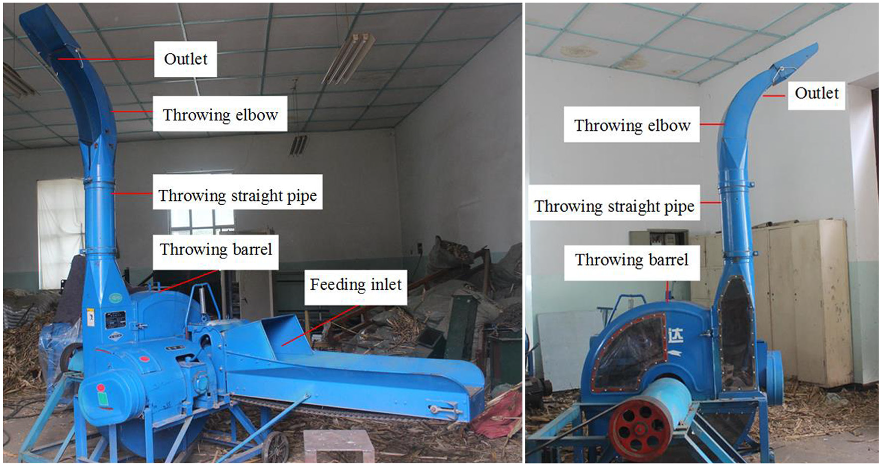
Structure sketch of the throwing device.

Knife dish.
When the machine is working, under the joint action of the feed device pushing and the moving knife cutting, the cut maize straw first obtains an initial velocity and then moves down rapidly. Sometime later, it collides with the throwing blade. After colliding, it obtains a velocity along the radial direction and moves along the radial direction of the throwing blade. At the same time, the rotating blade throws the material away from the blade. Then the material enters the throwing straight pipe. Owing to the effect of airflow, the material enters the throwing elbow and moves along the wall of the elbow. Finally, it is thrown out of the outlet. There are five stages of material movement in Table 1.
Material movement stage.

Dynamic analysis of material along with throwing blade
To study material movement problem, taking corn straw as the research object, this paper makes the following assumptions: (1) The collision between material and blade is assumed to be inelastic; (2) The displacement of material during colliding is assumed to be zero. Because the collision time between material and blade is short, the position change of material on the blade from the beginning of colliding to the end will be very small, so the displacement of material during this process can be neglected, and only the change of velocity before and after colliding can be considered; (3) To embody the interaction among airflow, material and throwing blade, equivalent friction coefficient fv 11 is introduced.
Taking throwing blade backward as an example, the force analysis of material moving along throwing blade is shown in Figure 3. The feeding inlet and wheel hub of knife dish are on the same horizontal plane. O is the origin of the fixed coordinate system xOy and is in the center of the wheel hub. For the balance and stability of the blade in the process of rotation and cutting, a reinforcing rib connection with a length of R0 (m) between the wheel hub and the blade. O’ is located at the junction of the blade and reinforcing rib. O’ rotates with the throwing blade, it is set as the origin of the dynamic coordinate system x‘O’y’. In the course of material movement, in addition to gravity (G), centrifugal force (FL) produced by a blade rotation, Coriolis force (FC) produced by the interaction of material movement along the blade (relative motion) and material rotation with blade (involvement motion), the direction of FC conforms to the right-hand judgment rule, as well as the friction force (Ff) and support force (N) of the blade to material. Other related variables and their meanings are listed in Table 2. The disc knife chaff cutter’s moving knife and the throwing blade share a knife dish, the effect of the cutter on material must not be slighted while studying the movement of the material in the throwing device.
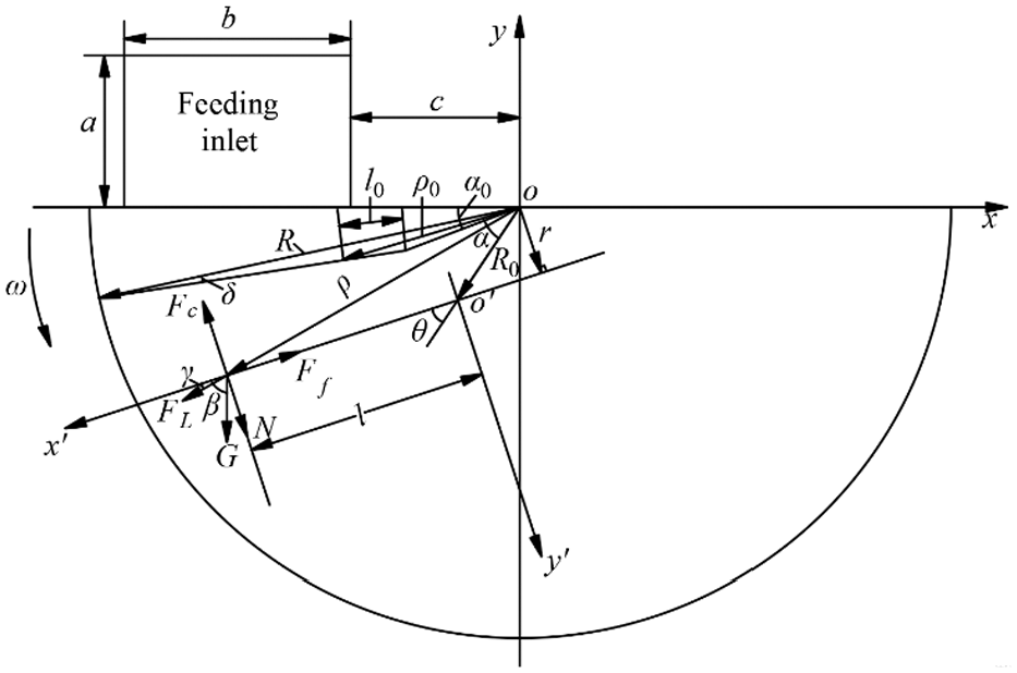
Force analysis of material moving along blade.
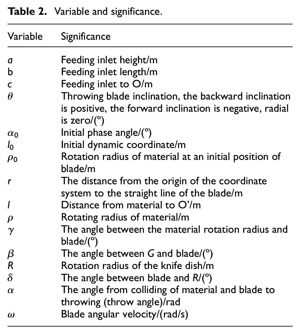
Variable and significance.
Motion of material before colliding with throwing blade
As a result of the structure of the knife dish, the cut straw will not collide with the throwing blade immediately but strike with the blade after a period of movement. While the material strikes with the blade, the velocity of the material will not be zero, and the direction of the velocity has a certain angle with the tangential direction of the blade rotation, and the material will obtain a radial initial velocity along with the blade motion. After the material collides with the blade, it will first move outward along the blade.
The initial velocity of the chopped maize straw is a combination of the velocity provided by the feeding device (i.e. the feeding velocity) and the implicated velocity of the cutter rotary cutting, which can be described as:

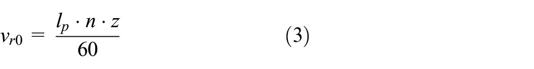
Where v0 is the initial velocity of the material, m s−1; vr0 is feeding velocity, m s−1; ve0 is initial implicated velocity, m s−1; r0 is initial rotation radius of the material, m, the value range is c≤r0≤b + c; n is spindle speed, rpm; lp is the length of material, m; z is the number of moving knife.
After the material moves for a period, it collides with the blade. The process of maize straw from chopping to knocking against the blade is written by the kinetic energy theorem as:

It can be obtained that the material velocity at the moment of collision is:

Where m is material mass, kg; g is gravity acceleration, m s−2.
The collision process between material and throwing blade
When the material collides with the blade, the angular velocity of the material is ω′, and the energy consumption is E11: 19


Where J is the moment of inertia of the blade, kg·m2.
After colliding with the blade, the angular velocity of the material accelerates from ω′ to ω. At the same time, the radial initial velocity along the blade direction after colliding is obtained, and the material starts to move along the blade radial direction. The energy consumption E12 in this process is expressed as follow:

From momentum moment theorem: 20

Therefore, the total energy consumption of this process can be calculated as:
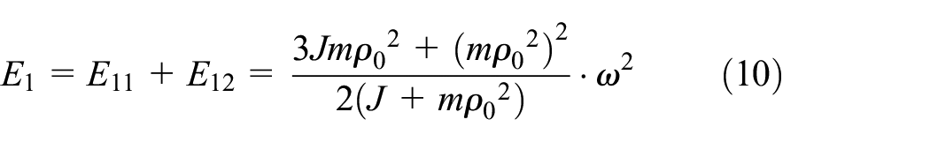
Because of
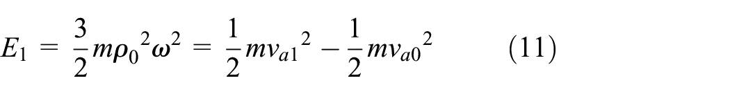
Where va1 is absolute velocity after hitting, m s−1.
The va1 is decomposed into the implicated velocity generated by the blade rotation and the relative velocity along with the blade radial motion (i.e. the initial radial velocity along the blade direction), as shown in Figure 4. It can be obtained that


Decomposition of material velocity after colliding (t = 0).
In the formula, ve1 is implicated velocity after colliding, m s−1; vr1 is radial initial velocity after colliding, m s−1.
Dynamic analysis of material on throwing blade
When t = 0, material moves along the throwing blade at the radial initial velocity vr1. The force analysis of material during the movement is shown in Figure 3.
The material moves along the blade, the force is balanced in the direction of y’ axis. It can be represented as:

Where
The support force of the blade to the material is equal to vertical positive pressure, the direction is opposite. The direction of vertical positive pressure is negative along y’ axis. Therefore, the vertical positive pressure of material to the blade is as follow:

The friction resistance caused by the movement of material relative to the blade is:

From Figure 3, the following geometric relationships can be obtained:
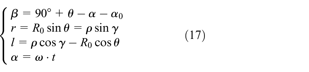
For these conditions and the introduction of relationships, the dynamic equation of particle movement can be derived as follows:

Where
Combined boundary condition
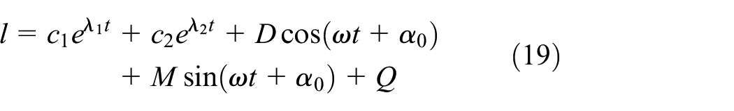
Where
When t = t1, material travels to the end of the blade and is thrown out, and then enters the straight pipe. At this moment, the relative velocity of material is vr2 (m s−1), and implicated velocity at the end of the blade is ve2:

It can be found that the absolute velocity of material at the time of throwing is calculated by:

Where va2 is absolute velocity of material at the end of the blade, m s−1.
Motion analysis of material after leaving throwing blade
Motion of material in throwing straight pipe
For the sake of obtaining the best trajectory of material, improve the throwing efficiency, and reduce the energy consumption, the collision and friction between the material and the throwing barrel should be minimized or avoided. Therefore, this paper assumes that the angle between the absolute velocity (va2) and the horizontal direction while the material leaves the throwing blade is 90º, that is, vertical upward.
The motion of material in the throwing straight pipe is related to the airflow velocity. Under the stable working condition of the machine, the airflow velocity gradient in the straight pipe is very small, it is considered that the single-particle material does not rotate, and the effect of material rotation on its force can be ignored. 21 Assuming the airflow velocity in the throwing straight pipe is vq (m s−1), the material movement may include the following two processes:
If va2 is greater than vq, the force acting on the material is resistance.
The velocity of the material decreases gradually due to the effect of airflow resistance, which leads to va2 is less than vq, the effect of airflow on the material is represented by aerodynamic force.
As can be seen in Figure 5, suppose there are two processes. After the material enters the straight pipe, first, the material velocity is greater than the airflow velocity. And then, while the material moves to a height of H1, the two velocities are equal. In this process, the forces acting on the material are the air resistance F1 and the gravity G of the material itself.

The movement of material in the throwing straight pipe and elbow.
Air resistance F1 is:

Since the material studied is cylindrical, its shape and size have a certain influence on its flow characteristics in the airflow, the equal volume equivalent diameter dv 22 is introduced in calculating the projection area of the material.
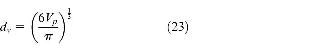
In the formula, v is the relative velocity of airflow and material, m s−1; ρ1 is the air density, ρ1 = 1.225, kg/m3; S is the projection area of material perpendicular to the plane of airflow, m2; Vp is the volume of material particles, m3; C is the resistance coefficient of material in the airflow.
Therefore, the differential equation of material motion has the form
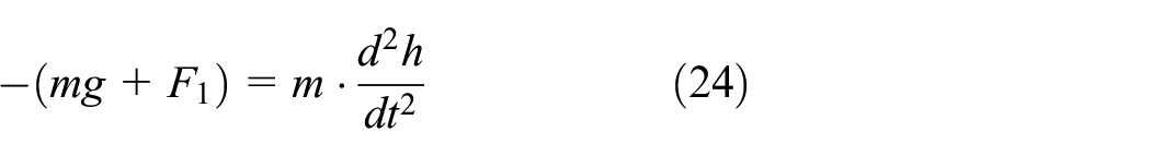
t = t1 is the initial time of this process. On account of the influence of the airflow velocity, the initial boundary conditions are
When t = t2, the material travels to the height of H1, the velocity is va3 (m s−1) and va3 = vq. Thereafter, the airflow velocity will be greater than the material velocity, and the airflow will exert aerodynamic force on the material. The magnitude of aerodynamic force is equal to that of F1, the direction is opposite. The differential equation of particle movement for this moment is as follows:
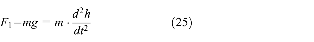
The initial boundary conditions are:
In the stage of the material moving along the throwing straight pipe, if material velocity is greater than airflow velocity when material throws out the blade, the material movement in the throwing straight pipe includes the two processes described in this section. If not, it has only the second process expressed in this section.
Motion of material in throwing elbow
When t = t3, material strikes the elbow wall. Considering the impact process time is short, the time and displacement of this process can be ignored, and only the velocity changes before and after are under consideration. When material strikes the elbow surface, the velocity is va4 (m s−1). After impact, material velocity changes to va5 (m s−1), and the material moves along the arc of the elbow wall. Under these circumstances, the forces acting on the material are gravity (G), friction (Ff’), centrifugal force (FL’), as described in Figure 5. Corn straw is a viscoelastic biological material, the kinetic energy will be lost when rubs against the pipe wall, so it is deemed to an inelastic collision. The expression of each force is:


Where R1 is the radius of curvature of the elbow, m; s is the arc length of material movement, m; f is coefficient of particle friction on the elbow surface.
In virtue of the short hitting time, the kinetic energy lost by the material can be regarded as the kinetic energy component of material along the direction of centrifugal force during striking. Particle velocity after hitting is therefore

Where s0 is initial arc length, m.
The differential equation of material movement along the elbow can be presented according to the relationship below:
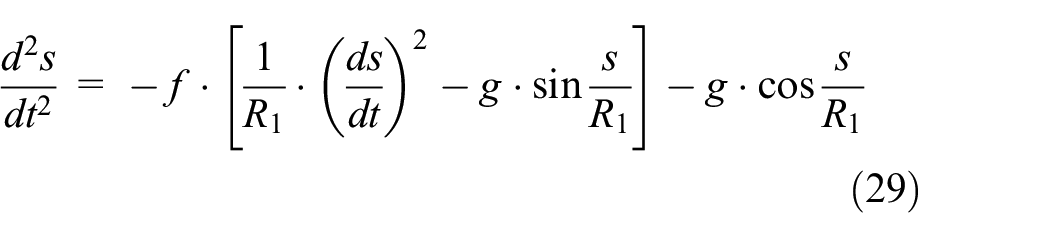
t = t3 is the initial time of this section, the initial boundary condition is s = s0,
Dynamic analysis of material after leaving outlet
When t = t4, the material is thrown out from the outlet of the chaff cutter. At present, assuming that the velocity of material is va6, the angle between the velocity and horizontal direction is φ. The force analysis and the trajectory of material after leaving the outlet are shown in Figure 6. At this juncture, the force acting on the material is gravity G and air resistance Fk.

Force analysis and movement diagram of material after leaving the outlet.
The dynamic equation of material thrown out is described by equations (30) and (31), respectively.
Horizontal direction (i.e. x-axis direction):

Vertical direction (i.e. y- axis direction):

The initial time of material discharging from the outlet is t = t4, the boundary conditions are
Verification and analysis
With the purpose of getting a more intuitive understanding of material movement law in each stage, this section establishes a MATLAB/Simulink simulation model based on the mathematical model in section 2-3, and combined with airflow velocity test, uses the simulation model to analyze material motion law, and verifies the correctness of the model by comparing the throwing distance test results with the numerical calculation results. It is of great significance to reveal the mechanism of material throwing, optimize the structure and motion parameters.
Model construction
According to the mathematical model in section 2-3 of this paper, the MATLAB/Simulink simulation model in different stages is established. There are many modules in the simulation model. To make the interface look clear, the model is encapsulated, as presented in Figure 7. The initial parameters of the model is spindle speed, blade inclination, elbow length, and other parameters and material characteristics (material length, density, etc.). These initial values are set according to the actual structure parameters and motion parameters of the chaff cutter and material characteristics. The output of the model is material velocity and displacement curve in the corresponding stage. Using the MATLAB/Simulink simulation model, the material velocity characteristic curve and displacement curve of each stage are drawn, so as to better understand the material movement law.

Simulation block of the first stage.
Airflow velocity test
For the sake of making the calculation results more accurate, the airflow velocities corresponding to different spindle speeds in the model need to be measured by experiments.
The experiment was carried out on the 9Z-6A disc knife chaff cutter test rig, as seen in Figure 8. The spindle speed is controlled by the VARISPEED-616G5 frequency converter, as shown in Figure 9. The measurements were performed with Testo425 anemometer, with an accuracy of 0.03 m s−1, as shown in Figure 10. The measuring points are arranged at the cross-sections A and B showed in Figure 8. Two holes should be punched at the sections A and B to enable the anemometer probe to be inserted into the pipeline. The location of the holes and the outlet port are on the same side. The anemometer probe is inserted into the hole to measure. The position of the probe in the cross-section is shown in Figure 11. The distance from the probe to the hole at position 1(3) is 124.5 mm, at position 2(4) is 62.3 mm. During machine operation, the wind speed at each position is measured by an anemometer. The measurements were performed in triplicate, and the average airflow velocity in the outlet pipe is obtained by taking the average value. The airflow velocities corresponding to different rotational speeds are recorded in Table 3.

Test rig.

Frequency converter.

Testo425 anemometer.

Location of measuring points.
Test results of airflow velocity.

Simulation results and analysis
The knife dish speed was set at 440 rpm, 510 rpm, 580 rpm, 650 rpm, and 700 rpm in this numerical simulation. The simulation analyzed the movement of material in each stage and calculated the corresponding throwing distance. In wake of the changement of spindle speed, the velocity of airflow and material is also changing, but the law of material movement is basically the same. Therefore, the material movement in each stage is analyzed with the spindle speed of 650 rpm as an example. The rest of the parameters linked with the employed in the simulation are set out in Table 4. The ode45 is adopted as the solver and the step is variable according to its precision.
Simulation parameters.

Figure 12 shows the velocity and displacement characteristic curves of the material moving along the blade. It can be seen from Figure 12(a) that the velocity of the material moving along the blade first decreases and then increases. The main reason for this phenomenon is the influence of the centrifugal force. After colliding with the blade, the material moves outward along the blade at the radial initial velocity of 25.05 m s−1. At this point, the resultant force of gravity and centrifugal force in the direction of the blade is less than the friction force, the material slows down along the blade. As material moves outward along the blade, the centrifugal force gradually increases. When the combined force of gravity and centrifugal force in the direction of the blade is greater than the friction force, material starts to accelerate until it is thrown away from the blade. The velocity in the direction of the blade is 26.04 m s−1 (t = 12.53 ms) as the material moves to the endpoint of the blade and throws out (Figure 12(b)).

Velocity and displacement curve of the material moving along the blade: (a) Velocity and (b) Displacement.
Figures 13 and 14 presents the velocity and displacement curve of material passing through the throwing straight pipe. Figure 13 shows the velocity and displacement curves of va > vq. It is clear from Figure 13(a) that material runs into the throwing straight pipe at the initial speed of 30.39 m s−1, it is a combined speed of the relative velocity along the blade and the implicated velocity generated by the blade rotation. Since material velocity is greater than air velocity, material movement is in the second stage described in section “Throwing Principle”. Owing to the influence of gravity and airflow resistance, the material will decelerate at this stage. When t = 247.77 ms, material velocity drops to 19.89 m s−1, equal to the wind speed measured in Table 3. At this point, from Figure 13(b), material movement height is 1.301 m and the third stage of material movement begins. Figure 14 shows the velocity and displacement curves of va < vq. According to the calculation of the parameters in Table 4, while material moves to 1.882 m, it will hit with the elbow. As can be seen from Figure 14(a), When t = 225.902 ms, the particle strike the elbow wall. The temporal variation of the velocity of the material in this process is shown in Figure 14(b). It can be seen that the material speed decreased from 19.89 m s−1 to 14.74 m s−1. This is because in this stage, although the airflow provides power to material, the air force it receives is less than its gravity because of its small stressed area, the material continues to decelerate.

Velocity and displacement curves of va>vq. (a) Velocity and (b) Displacement.

Velocity and displacement curves of va<vq. (a) Displacement and (b) Velocity.
Figure 15 describes the velocity and displacement curve of material passing through the throwing elbow. Material strikes the elbow wall, part of the energy is lost and thus the speed is reduced from 14.74 m s−1 to 11.77 m s−1. Under the influence of centrifugal force, the material moves along the arc. In the same way, the centrifugal force is also responsible for the pressure of particles on the upper arm of the elbow, causing friction between the particles and the elbow wall, resulting in increased resistance. Accordingly, in the course of motion, the impact of friction and corresponding component of gravitational force lead to a deceleration in material, which is consistent with the phenomenon described in Figure 15(b). It can be revealed from the figure that the material velocity is 9.849 m s−1 as is thrown out from the spout. This speed determines the throwing distance of material.

Velocity and displacement curves of materials passing through the throwing elbow: (a) Displacement and (b) Velocity.
Figure 16 shows the displacement curves of materials in a vertical direction. When the material is thrown out, there is a certain angle between the speed and the horizontal direction, which makes the material throw obliquely upward. Under the action of air resistance and gravity, the component velocity in the y-direction continuously decreases until to be zero, and then accelerates in the negative direction of the y-axis. Meanwhile, the component velocity in x-direction eventually decreases due to the air resistance. Therefore, the material first moves upward for a certain distance, then moves downward until lands on the ground. Through numerical calculation, the final throwing distance is 5.794 m.

Displacement curves of materials in vertical directions.
Test verification
According to the established simulation model, the actual measured throwing distance is compared with the simulated throwing distance under different spindle speeds to verify the accuracy and reliability of the model. The comparison of the simulation and the test results are made under similar conditions.
The experiment was carried out on the test rig shown in Figure 8. In this procedure, the test materials were performed with yellow corn straw, and the moisture content was about 20%. A waterproof cloth (8 m long and 6 m wide) was placed under the outlet so that all the materials fall on the waterproof cloth. Each experiment was performed several times, and the throwing distance of each test was recorded, their average was finally taken. The experimental and simulation results are shown in Figure 17. By comparing and analyzing the experimental and simulation data, it can be obtained that the maximum relative error between the simulated value and the experimental value is 9.42%. Because the study material is agricultural fiber material, considering the non-uniformity of its rheological properties and the anisotropy of the material, the relative error is generally considered to be accurate within 10%. 10 The measured values are greater than the simulation values, this phenomenon occurs as a result of the effects caused by the measure of instrumental errors and the interference of outdoor wind.

Test and simulation results.
The feasibility and accuracy of this method have been verified in the throwing test. Therefore, the parameters of the chaff cutter can be optimized and predicted quickly according to the simulation results, which provides an important reference index for the test and reduces the test cost.
Conclusions
In this paper, the single material is the research object, and the dynamic theory is taken as the research foundation. Taking the matching problem between throwing device and front-end device into account, analyzed the force and movement of material in each stage. The conclusions are as follows:
The dynamic model of material from chopping to landing was established. In this model, the effects of feeding velocity, cutter, and airflow on material, as well as the relationship between the structure parameters and motion parameters of the throwing device of the cutter and the movement state of the material are considered.
The MATLAB/Simulink simulation model of material motion is established. Through simulation analysis, it is found that the material only accelerates in the process of moving along the blade, and decelerates in other stages, which means the blade plays a major role in the process of throwing materials.
The simulation results are basically consistent with the test results. The maximum relative error between the simulation values and the test values is 9.42%. It proves that the established mathematical model and the MATLAB/Simulink model are correct and reliable.
In this study, the single material particles in 9Z-6A disc knife chaff cutter were studied, and simulated by MATLAB/Simulink. Although the feasibility and accuracy of this method have been verified in the throwing test, there is still a certain gap between the actual corn straw state and the real corn straw movement characteristics. It can be further studied how to use the simulation method to further approach the kinematic and dynamic characteristics of corn straw in the later stage.
In addition, from the point of view of multi-material particles, combined with discrete element method, the mass movement law of materials must be studied to find out the reasons of high power consumption, low efficiency and residue blockage of the chaff cutter, optimize the performance parameters, and solve the problem of high power consumption, low efficiency and residue blockage.
Footnotes
Handling Editor: James Baldwin
Declaration of conflicting interests
The author(s) declared no potential conflicts of interest with respect to the research, authorship, and/or publication of this article.
Funding
The author(s) disclosed receipt of the following financial support for the research, authorship, and/or publication of this article: This work was supported by the National Natural Science Foundation People’s Republic of China (grant number 51865047) and the Natural Science Foundation of Inner Mongolia Autonomous Region (grant number 2018MS05002).