
Abstract
In order to develop an electrical continuously variable transmission (E-CVT) to replace mechanical power coupling equipment applied in series-parallel hybrid electric vehicle (HEV), this paper proposes a magnetic-field modulated brushless dual-mechanical port motor with Halbach array permanent magnets, which has a more compact structure. The operating characteristics are analyzed by the lever analogy. It is concluded that the motor can realize the speed and torque decoupling between the engine and the wheel, which meet multi-mode operation requirements for HEV. To realize the multi-objective design of torque output, torque ripple and usage amount of permanent magnets, an optimization scheme combined parameter sensitivity with response surface methodology is adopted. The trade-offs among the optimization objectives are considered, then the key structural parameters and its optimal values are efficiently determined. Based on a two-dimensional model, the electromagnetic performances are simulated and analyzed. The results show that, after the parameters optimization, the no-load back electromotive force (EMF) has better sinusoidal characteristic, and the torque ripples and cogging torque peaks of the motor have been significantly reduced. Furthermore, a prototype motor is tested. The experimental results are consistent with the simulation results, which demonstrates the validity of the proposed structure and parameter optimization method.
Keywords
Introduction
HEVs have the advantages of good driving performance, long driving distance, low pollution, low noise, and braking energy recovery, which are regarded as one of the ideal energy-saving and environmentally friendly vehicles at present, especially for series-parallel HEV. 1 The power coupling system can reasonably distribute the power flow between multiple power sources of HEVs and realize multiple working modes to meet the needs of variable driving conditions, which plays an important role in the development of entire vehicle. As is well known, some typical power coupling configurations of series-parallel HEV such as Prius THS, 2 Chevy Volt, 3 and Corun CHS, 4 use a planetary gear mechanism for power splitting. These power-coupling systems can independently control the speed and torque of internal combustion engine (ICE) with high efficiency, but which also bring some problems of vibration, noise and difficulty in maintenance. 5 Hence, E-CVT was proposed more than ten years ago. 6
The E-CVT is also called as four-quadrant transducer (4QT) 7 or dual-mechanical port (DMP) motor,8–10 which essentially belongs to the category of dual-rotor motor (DRM), and can realize the same function of the planetary gear mechanism, generator and motor in THS. Some scholars investigated parameters optimization design,11,12 thermal analysis,13,14 and magnetic coupling problem15,16 of the E-CVT. The results show that E-CVT has advantages of high power density, compact structure and easy control; and the hybrid powertrain based on E-CVT can reduce fuel consumption and CO2 emissions more than 30%. However, it also has some problems, such as magnetic coupling, extra power losses and poor reliability caused by the brushes and slip rings of inner rotor winding, and difficult to solve the overheating of inner rotor windings, which are largely attributed to the particular structure of DRM with brushes and slip rings. Therefore, to avoid these problems, it is necessary to develop brushless DRM.
Atallah et al. 17 applied the magnetic-field modulated (MFM) principle to magnetic gears composed of two permanent magnet (PM) rotors with different pole pairs, which can transfer different speeds. Moreover, the motor integrated with magnetic gears has a feature of low speed and high torque, and it can be applied in electric vehicles. 18 Thus, some brushless MFM-DMP permanent magnet motors used for HEVs were investigated.19,20 However, the torque regulating function of these motors is realized by an additional permanent magnet motor. The entire electrical power coupling system is longer in the longitudinal direction and has a large volume, which is not conducive to the lightweight of the vehicle.
The main purpose of this paper is to develop an E-CVT with a smaller volume applied in series-parallel HEV. According to the MFM principle, the rotating permanent magnetic field of inner PM rotor in magnetic gears is substituted with the rotating magnetic field generated by the armature windings of inner stator. The modulation ring rotor and the outer PM rotor are considered as two independent rotors. Furthermore, the Halbach array is adopted in the arrangement of inner and outer PMs of outer rotor. Then, a novel MFM brushless DMP motor with Halbach array PMs (HMFM-BDMPM) is proposed in this paper. In fact, the HMFM-BDMPM is a four-port motor, which includes two mechanical ports and two electrical ports. Due to the integrated structure and complicated energy conversion, it is difficult to understand the power transmission relationship and determine optimal structure parameters. Therefore, this paper presents a graphical method to analyze the speed and torque relationships of the HMFM-BDMPM, and a multi-objective optimization method based on the combination of sensitivity analysis and response surface methodology to optimize structure parameters.
This paper is organized as follows: Section 2 introduces the structure and working principle of the HMFM-BDMPM, and the operating characteristics are analyzed by the lever analogy in Section 3. The structure parameters are optimized by the multi-objective optimization method in Section 4. Based on a two-dimensional finite element model, the electromagnetic performances before and after the optimization are compared in Section 5. Section 6 verifies the validity of proposed structural scheme and simulation results by experiments. The conclusion and future research are presented in the final section.
Structure and principle of the HMFM-BDMPM
The HMFM-BDMPM is integrated by an inner magnetic-field modulated PM motor (IMFM-PMM) and an outer PM synchronous motor (OPMSM) sharing the outer rotor, as shown in Figure 1. To reduce the speed adjustment range of the inner stator magnetic field, a planetary gear mechanism was laid out between the ICE and the HMFM-BDMPM. The IMFM-PMM is similar to modulated magnetic gear, and consists of the inner stator, the modulation ring rotor and the inner PM of outer rotor. There are a certain amount of magnetic conduction blocks and non-magnetic conduction blocks arranged alternately in the modulation ring rotor, as shown in Figure 2. The OPMSM is composed of the outer stator and the outer PM of outer rotor. The ICE is connected to the sun gear, the planet carrier is connected to the modulation ring rotor, the gear ring is fixed, and the outer rotor is connected to the final drive of vehicle.

Hybrid drivetrain based on the HMFM-BDMPM.
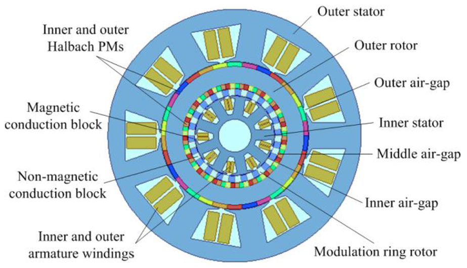
Cross-section diagram of the HMFM-BDMPM.
Under the action of the modulation ring rotor, the magnetic fields in the inner and middle air-gap change remarkably. The modulated magnetic fields will generate, which can further realize the energy conversion in the IMFM-PMM. To avoid the influence of magnetic coupling, the inner and outer PMs of outer rotor were arranged in Halbach array. The reason is that the Halbach array has a characteristic of magnetic self-shielding, which can effectively shield the magnetic field on one side and strengthen the magnetic field on the other side. It has a more sinusoidal air-gap magnetic field than the conventional structure, and shows high torque density, low torque ripple and little core loss. Since the speed of modulation ring rotor and outer rotor can be controlled independently by adjusting the speed of inner stator magnetic field, the IMFM-PMM can decouple the ICE speed and the wheel speed. However, the torques transmitted by these two rotors in the IMFM-PMM are proportionate, so the OPMSM is used to decouple the ICE torque and the wheel torque. Hence, the HMFM-BDMPM can realize that the speed and torque of the ICE are completely independent of the wheels, which can be applied in series-parallel HEV like THS.
Because the OPMSM can be regarded as a traditional PM motor, the IMFM-PMM has a complex structure with two mechanical ports and one electrical port, so the speed and torque relationships of various parts are more complicated. In the next section, the lever analogy is mainly adopted to analyze the operating characteristics of the IMFM-PMM.
Characteristics analyses of the HMFM-BDMPM
The lever analogy is a method to simplify the motion of planetary gear set by equating to a lever model. It is mostly used in the design of automatic transmissions. In recent years, several scholars have also applied it to the transmission scheme design of E-CVT for series-parallel HEV.21,22
In order to explain the operating characteristics of the IMFM-PMM, the following assumptions are made:
The pole pairs number of inner stator magnetic field and inner PM field of outer rotor are psi and pro-PMi, respectively, and the number of magnetic conduction blocks is Nrm.
The speeds of inner stator magnetic field, modulation ring rotor, and inner PM field of outer rotor are nsi, nrm and nro, respectively.
The electromagnetic torques acting on inner stator magnetic field, modulation ring rotor, and inner PM field of outer rotor are Tsi, Trm and Tro-PMi, respectively.
Speed relationship of the IMFM-PMM
According to the MFM principle, the relationship of psi, Nrm and pro-PMi is expressed as:

The relationship of nsi, nrm and nro is expressed as:

Combining equations (1) and (2), the following equation can be obtained:

Assuming

The lever analogy is adopted to illustrate the relationship of nsi, nrm and nro, as shown in Figure 3. Point A, B and C represent inner stator, modulation ring rotor and inner PMs of outer rotor, respectively, which are in a line. Assume that the distance between point A and B is λ, and the distance between point B and C is 1. The line segment perpendicular to line ABC represents the value and direction of speed. In addition, the length of line segment represents speed value, and the speed direction is specified as follows: it is positive above line ABC, on the contrary, it is negative.
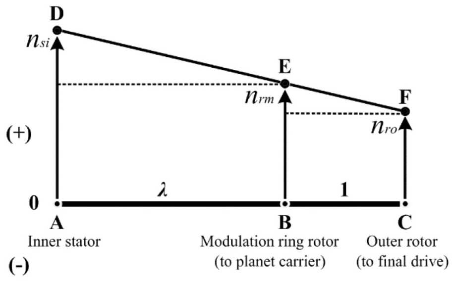
Diagram of collinear speed.
Thus, nsi, nrm and nro can be expressed by line segment

Combining equations (4) and (5), it can be obtained:

It shows that point D, E, and F are also in a line. That is, the speeds of inner stator magnetic field, modulation ring rotor and inner PMs of outer rotor are always collinear, which accord with the relationship of lever. While any two speeds of those are given, the value and direction of the third speed is easy to determine. Therefore, for the IMFM-PMM, when the speed of outer rotor caused by the wheel load changes, the speed of modulation ring rotor can be kept constant by adjusting the speed of inner stator magnetic field. Thus, it can maintain ICE working in high fuel efficiency zone.
Torque relationship analysis of the IMFM-PMM
Based on the MFM principle, this section will analyze torque relationships and energy transformation among three ports. Firstly, the positive directions of speed, torque and power are given as follows:
The positive direction of both the speeds and the torques of inner stator magnetic field, modulation ring rotor and inner PMs of outer rotor are specified to be counterclockwise.
The power output from the port is positive. Conversely, the power input the port is negative.
The electrical power (Psi) at inner stator port is expressed as:

Note that the positive electrical power means that the IMFM-PMM works as a generator, and the negative electrical power means that the IMFM-PMM works as a motor.
The mechanical power (Prm and Pro-PMi) at the port of modulation ring rotor and inner PMs of outer rotor are respectively expressed as:


When all losses are ignored, the IMFM-PMM keeps to the law of energy conservation. Therefore, the sum of both the powers and the torques of three ports should be zero, respectively.


Combining equations (10) and (11), it can be obtained:

According to equations (4) and (12), it can be obtained:
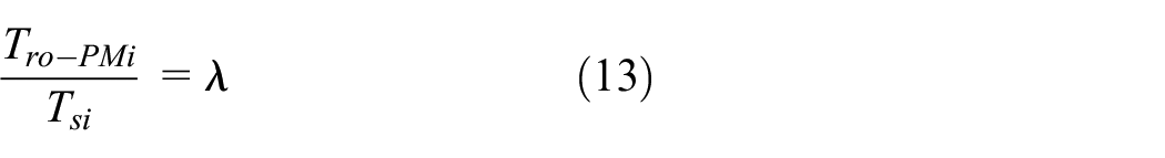
Substituting equation (13) into equation (11), it can be obtained:


In equations (14) and (15), the negative sign indicates the reverse direction of two torques. The relationships of Tsi, Trm and Tro-PMi can also be illustrated by the lever analogy, as shown in Figure 4. Point A, B, C and the distances between them have the same definitions as previously mentioned. The difference is that the line segment perpendicular to line ABC represents the value and direction of torque, and the length of line segment represents torque value. The torque direction is specified as follows: it is positive above line ABC, otherwise it is negative.

Diagram of lever-balancing torque.
If the torques acting on point A, B, and C are equivalent to the forces, it is easily found that the sum of the torques acting on A, B, and C equals zero. Meanwhile, when any one of point A, B, and C is selected as a pivot point, the algebraic sum of the product of the torque and the corresponding force arm for the other two points also equals zero.
For instance, if point A is selected as pivot point, the following torque equilibrium equation can be obtained:

Similarly, if point B and C are selected as pivot points, respectively, the torque equilibrium equations can be obtained as follows:


Note that, the algebraic values of Tsi, Trm and Tro-PMi are considered in equations (16)–(18). Compared equations (12)–(15) with equations (16)–(18), it can be seen that two sets of equations are consistent. Thus, when any torque acting on inner stator, modulation ring rotor and inner PMs of outer rotor is given, it is easy to determine the torque value and direction of the others. Besides, it shows that the torque directions of inner stator and inner PMs of outer rotor are always the same, which are opposite to that of modulation ring rotor.
From the above analysis, we can draw a conclusion that the IMFM-PMM can realize speed decoupling, but it cannot decouple torque among three ports.
Torque decoupling analysis of the OPMSM
When the armature windings of both the inner stator and the outer stator are connected to three-phase current, the outer rotor bears modulation torque (Tro-PMi) generated by the IMFM-PMM under the action of modulation ring rotor. Meanwhile, it also bears electromagnetic torque (Tso) generated by the OPMSM under the influence of outer stator magnetic field. Then the two torques are superimposed and transmitted to final drive. Assume the output torque of the HMFM-BDMPM is Top, the relationships of Tro-PMi, Tso and Top can be expressed as:

Note that, in this case, the speeds of outer stator magnetic field, inner PMs of outer rotor and the HMFM-BDMPM output are the same as nro. Because the windings currents of inner stator and outer stator can be controlled independently, the electromagnetic torque generated by the OPMSM can be regulated freely to meet the load torque changes of the wheel. Thus, the output torque of ICE can be kept constant, which maintains ICE working with a high fuel-efficient.
Structural parameters optimization of the HMFM-BDMPM
Initial parameters design
From the structural form, the HMFM-BDMPM can be regarded as a cascade connection of the IMFM-PMM and the OPMSM in radial space. The power equation is expressed as:

Where Ds is armature diameter, lef is active length of armature core, PN is rated output power, KE is ratio of induced electromotive force to terminal voltage at rated load, αp is pole-arc coefficient, KB is waveform coefficient of air-gap magnetic field, Kdp is winding coefficient, Bδ is air-gap magnetic flux density, A is line load, ne is rotated speed, η is motor efficiency, and cosφ is power factor.
It is noted that, for the IMFM-PMM, ne is rated speed of inner stator armature magnetic field, which is calculated according to equation (2). However, for the OPMSM, ne is rated speed of outer PMs of outer rotor.
Learning from previous design experiences, the stator pole-slot ratio of both the IMFM-PMM and the OPMSM is adopted as 10/9. Considering the effect on output torque of the motor, we select matching relationship between the number of magnetic conduction blocks and the pole pairs number of inner PM field of outer motor as 22/17. The magnet per pole number of inner and outer Halbach PMs of outer rotor is set at 2 and 3, respectively.
Whereupon, once the output power and rated speed of the IMFM-PMM and the OPMSM are determined, the initial values of main design variables can be calculated according to equation (20), as listed in Table 1.
Initial variables value and design specifications.

Parameters optimization
Due to the complex structure and many parameters of the HMFM-BDMPM, the optimization procedure is a heavy workload by the method of traditional single objective optimization or independent parameter optimization. Besides, the global optimal solution can not be obtained, and it is difficult to meet multiple optimization objectives simultaneously. Thus, this paper adopts an optimization design scheme with the combination of multi-objective sensitivity and response surface methodology. Firstly, parameters that have a greater impact on the optimization objectives can be screened out by sensitivity analysis. Then, by the combination of response surface methodology and multi-objective optimization algorithm, the optimal values of sensitive parameters are furtherly determined.
According to equation (20), when PN, ne and lef are given, Ds is a certain value. Therefore, the structural parameters of modulation ring rotor, and inner and outer PMs of outer rotor are selected as design variables. The parameterized geometry model is built as shown in Figure 5.

Parameterized geometry model.
Optimization objectives
Considering the application characteristics and cost requirement of the HMFM-BDMPM, this paper selects output torque, torque ripple, and usage amount of PMs (expressed by area) as optimization objectives. Among the three objectives, the output torque is more important to meet power demand of the vehicle firstly, and its weight coefficient is set at 0.6. The torque ripple and usage amount of PMs can be considered to have a lower equal importance, and their weight coefficients are set at 0.2, respectively.
The functions of three optimization objectives are expressed as:
Output torque: max (avg (Torque))
Torque ripple: min (pk2pk (Torque)/avgabs (Torque))
Assume that krip denote the ratio of pk2pk (Torque) to avgabs (Torque), the expression can be written as:

Where, Tmax and Tmin refers to the highest value and the lowest value of the output electromagnetic torque for the IMFM-PMM and the OPMSM in a cycle, respectively; and Tavg is the average value for them.
Usage amount of PMs: min (sum (MagnetArea))
The comprehensive objective function is constructed as:

Where f1(x), f2(x), and f3(x) are sub-optimization objective function, m1, m2, and m3 are weight coefficients of the corresponding sub-optimization objective.
Parameter sensitivity analysis
Sensitivity refers to the influence of input variables of the system on output variables. The variables with a relatively low sensitivity can be ignored, thus the input parameters that have a greater impact on the optimization objective can be screened out, which reduces the number of input variables and achieve efficient optimization design of the system. 23
According to the original values (Table 1) and the parameterized model (Figure 5), dm, Wm, dpmi, dpmo, and Wpmo are selected as optimization variables in the sensitivity analysis.
The parameter sensitivity analysis results of the IMFM-PMM and the OPMSM are shown in Figure 6(a) and (b), respectively. As can be seen, the parameters that have the greatest impact on the three-optimization objectives of the OPMSM are dpmo and Wpmo. For the IMFM-PMM, the parameters that have a main impact on output torque and torque ripple are Wm and dpmi. Besides, dpmo and Wpmo also have a certain effect on torque ripple, and dpmi has the greatest impact on usage amount of PMs. After comprehensive consideration, the key parameters of the IMFM-PMM are determined as Wm and dpmi, and those of the OPMSM are dpmo and Wpmo.

Sensitivity analysis results of structural parameters: (a) IMFM-PMM and (b) OPMSM.
Response surface analysis
Response surface indicates the relationship between output variables and a set of input variables. When there are fewer input variables in the objective function, the response surface methodology can be used to quickly find optimal solution of the system. 24
Based on the key parameters of the IMFM-PMM and the OPMSM determined previously, the response surface methodology was used to obtain the relationships between optimization objectives and each parameter.
Figure 7(a) shows the response of the optimization objectives of the IMFM-PMM to Wm and dpmi. The absolute value of average output torque increases first and then decreases with the increase of Wm, which reaches to the maximum at Wm = 8.5°. Meanwhile, it increases as dpmi, but the growth rate becomes slower after dpmi = 6 mm. The torque ripple decreases first and then increases with the increase of Wm and dpmi, which reaches to the minimum at Wm = 8.5° and dpmi = 7.5 mm, respectively. The usage amount of PMs increases linearly as dpmi. Therefore, the value of dpmi should be 6 mm to 7.5 mm, and the value of Wm should be about 8.5°.

Response surface analysis of the optimization objectives to key parameters: (a) IMFM-PMM and (b) OPMSM.
Figure 7(b) shows the response of the optimization objectives of the OPMSM to dpmo and Wpmo. The average output torque increases as dpmo, but the growth rate becomes slower after dpmo = 5.5 mm. Meanwhile, it increases linearly as Wpmo approximately. The torque ripple increases first and then decreases with the increase of Wpmo, which reaches to the maximum at Wpmo = 10.5°. The usage amount of PMs increases with the increase of dpmo and Wpmo. Therefore, Wpmo should be a higher value in the constraint range, and the value of dpmo should be about 5.5 mm.
Furthermore, after the trade-offs among the three objectives were fully considered, the feasible design points of the IMFM-PMM and the OPMSM were obtained by the multi-objective genetic optimization algorithm, as shown in Figure 8(a) and (b), respectively. At the same time, three candidate design schemes with high satisfaction were screened out. The optimal values of key parameters were finally determined as listed in Table 2.

Feasible design points after the optimization: (a) IMFM-PMM and (b) OPMSM.
Optimal value of key structural parameters after the optimization.

Evaluation of electromagnetic performances
Based on the optimized parameters, a two-dimensional finite element model was built. Some electromagnetic performances of the HMFM-BDMPM were simulated before and after parameter optimization.
No-load back EMF
Figure 9(a) and (b) show the comparisons of A-phase no-load back EMF waveforms of the IMFM-PMM and the OPMSM before and after parameter optimization, respectively. Compared with initial parameters, the optimized parameters can bring a better sinusoidal wave of back EMF for the OPMSM. The back EMF waves of the IMFM-PMM have good sinusoidal characteristic before and after the optimization.
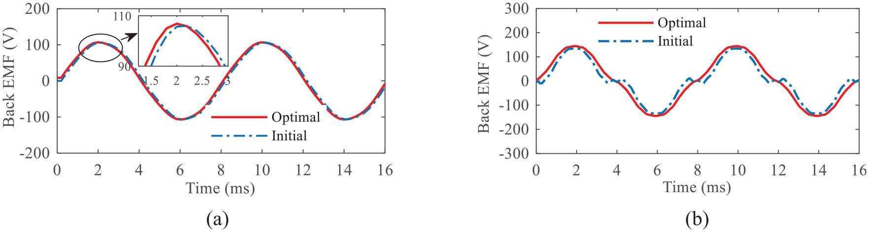
A-phase no-load back EMF before and after the optimization: (a) IMFM-PMM and (b) OPMSM.
Output torque and torque ripple
Figure 10(a) and (b) show output torque and torque ripple comparisons of the IMFM-PMM and the OPMSM before and after parameter optimization, respectively. As can be seen, the average output torques have a little changes, which accord with theoretical calculated values. However, the torque ripple reduces significantly after the optimization. The torque ripple coefficient of the OPMSM reduces from 0.152 to 0.103, and that of the IMFM-PMM reduces from 0.151 to 0.069. In addition, as seen in Figure 10(a), when the inner stator winding is separately excited (f = 125 Hz) and nrm is set at 0, nro is obtained as −441.2 r/min by equation (2). The simulation result shows that the torques subjected by the inner stator, modulation ring rotor and outer rotor are −12.92 N·m, 56.6 N·m, and −43.78 N·m, respectively, which meet the torque relationship of equation (11). So the correctness of the foregoing theoretical analysis was verified.

Output torque and torque ripple before and after the optimization: (a) IMFM-PMM and (b) OPMSM.
Cogging torque
Figure 11(a) and (b) show cogging torque comparisons of the IMFM-PMM and the OPMSM before and after parameter optimization, respectively. Compared with those of initial parameters, the cogging torque peaks of both motors have been significantly reduced after the optimization. For the OPMSM, the cogging torque peak decreases from 2.11 N·m to 0.51 N·m, and it decreases from 2.05 N·m to 0.61 N·m for the IMFM-PMM.
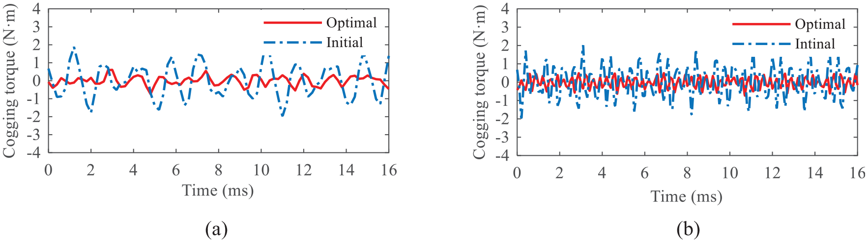
Cogging torque before and after the optimization: (a) IMFM-PMM and (b) OPMSM.
In summary, it is concluded that the electromagnetic performances of the HMFM-BDMPM have been well improved after the parameter optimization. With ensuring that the output torque meets power requirements, both the torque ripple and the cogging torque have been significantly reduced, which can effectively reduce the vibration and noise of the motor.
Experimental validations
In order to verify the rationality of the HMFM-BDMPM structural scheme and the validity of the parameter optimization method, a prototype motor was manufactured. Figure 12 shows the schematic of test system. The IMFM-PMM and the OPMSM are driven by a frequency converter. The positions of modulation ring rotor and outer rotor are obtained from an optical encoder. The loads of the IMFM-PMM and the OPMSM are built by using the electrical dynamometer to offer various load demands. The test bench for the HMFM-BDMPM is shown in Figure 13. The operating characteristics of the IMFM-PMM and the OPMSM were tested.

Schematic diagram of test system.

Test bench for the HMFM-BDMPM.
Figure 14(a) and (b) show the test and simulation results of A-phase no-load back EMF of the IMFM-PMM and the OPMSM, respectively. It can be seen that the variation trends of measured back EMF waveforms are basically in agreement with the parameter optimized simulation results aforementioned in Figure 9(a) and (b), which have a slight decrease in the peak, but they also exhibit the characteristics of sinusoid.

Comparison of A-phase back EMF by the test and simulation: (a) IMFM-PMM and (b) OPMSM.
The average torques and torque ripples of the IMFM-PMM and the OPMSM at various currents are depicted in Figure 15(a) and (b), respectively, which indicate that the test results are largely accorded with the simulation results. Besides, it can be seen that the relationships between the output torque and current are approximately linear. However, there are some small differences between the measured and simulation waveforms, which mainly result from the defects of manufacturing and assembling, limitation of testing conditions and measurement errors. Overall, the test results can reveal the validity of the proposed structural scheme and optimization method for the HMFM-BDMPM.
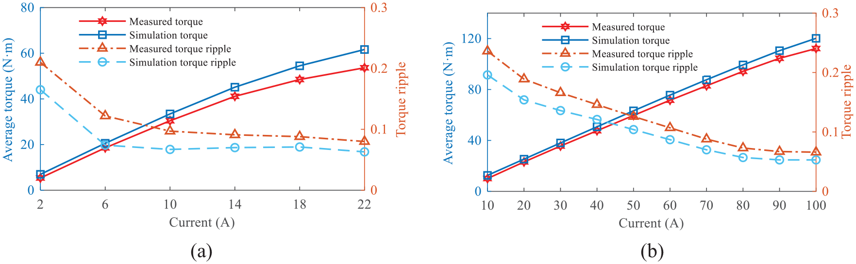
Comparison of torque and torque ripple by the test and simulation: (a) IMFM-PMM and (b) OPMSM.
Conclusions
In this paper, a new magnetic-field modulated brushless DMP motor with Halbach array permanent magnets and synthesizing multi-objective optimization method are proposed and investigated. By the lever analogy and the law of energy conservation, the operating characteristic analyses indicate that the HMFM-BDMPM can decouple the speed and torque between the ICE and the wheel to meet multi-mode operation requirements for series-parallel HEV, which can be taken as a potential alternative of planetary gear power coupling equipment. With the combination of multi-objective sensitivity analysis and response surface methodology, the tradeoff design among the optimization objectives of output torque, torque ripple, and usage amount of PMs is achieved efficiently. The simulation results of electromagnetic performances of the motor before and after the parameters optimization show that, after the optimization, the no-load back EMF has better sinusoidal characteristic; the torque ripples of the IMFM-PMM and the OPMSM have reduced by 54.3% and 32.2%, respectively; and the cogging torque peaks of the IMFM-PMM and the OPMSM have reduced by 70.2% and 75.8%, respectively. Meanwhile, the speed-regulating function of the IMFM-PMM is verified. The experimental results agree generally with the simulation results, which indicate that the proposed structure scheme and parameter optimization method are feasible.
In the future, the further research on thermal analysis and driving performance under different operating conditions should be carried on to lay the foundation for practical application of the motor in vehicle.
Footnotes
Handling Editor: James Baldwin
Declaration of conflicting interests
The author(s) declared no potential conflicts of interest with respect to the research, authorship, and/or publication of this article.
Funding
The author(s) disclosed receipt of the following financial support for the research, authorship, and/or publication of this article: This work was founded by the National Natural Science Foundation of China (Grant No. 51875258).