
Abstract
In IT business, the capacity of the battery in smartphone was drastically improved to digest various functions such as communication, Internet, e-banking, and entertainment. Although the capacity of the battery is improved, it still needs to be upgraded due to customer’s demands. In this article, we optimize the design of the linear generator with the Halbach array to improve the efficiency of harvesting vibration energy during human walking for the battery capacitance. We propose the optimal design of the tubular permanent magnet with the linear generator that uses a Halbach array. The approximate model is established using generic algorithm. Furthermore, we performed electromagnetic finite element analysis to predict the induced voltage.
Introduction
Due to the development of the information industry and related technologies, smartphone has many functions such as messages, Internet access, e-banking, and games. Although the entire battery capacity has been improved compared with that of old phone, the available usage time has decreased because of digesting various functions.
In order to address this problem, Park et al. developed an embedded linear generator for a self-rechargeable function. The linear generator is operated by resonance phenomenon. Electromagnetic force (EMF) is generated according to Faraday’s law, and the battery is recharged by EMF. In an existing linear generator, the battery can be recharged in walking and shaking mode. However, the generated electric power is not adequate because of low efficiency. Optimizations and conversion of array of permanent magnet (PM) are studying to resolve this problem. 1
There are many array types of PM in linear generator. The radial direction array was introduced by Ishiyama et al. 2 The magnets are placed face-to-face to generate mutual repulsion. However, the axial direction array, which is different from Ishiyama’s design, was introduced by Murphy. 3 The Halbach array is an arrangement of magnets that increases the magnetic field on one side of the array, while offsetting the field to nearly zero on the other side. The different types of rotating pattern of PM (left, up, right, and down) are used.4,5
Our proposed optimal design attempts to maximize the generated induced voltage. We can obtain optimum values that maximize the objective function using optimal design under constraint conditions. 6
In this study, we propose the Halbach array embedded in a smartphone in order to maximize generated induced voltage by applying to proper ratio of the radial and axial magnets. The optimum values, based on the commercial electromagnetic analysis software, ANSYS and Maxwell, show a more feasible design compared to the existing generator.
Generation system
Structure and principle of the Halbach array generator
Figure 1 shows the schematic diagram of the conventional tubular linear generator. It is composed of two main parts: a slider and stator. The slider is composed of PMs, and pole shoes serving as a conductor of magnetic flux. The stator is composed of the coils, housing, and two poles with three-phase coil windings. Two springs enable the slider to produce resonance.

Schematic diagram of conventional tubular linear generator.
Figure 2 shows a schematic diagram of the Halbach-array-type linear generator. The Halbach array generator consists of PMs following axial- and radial-direction PMs. One-sided magnetic flux was introduced by Mallinson, 7 and the Halbach array was developed by Halbach. 8 In case of the Halbach array shown in Figure 3, if the axial and radial PMs were magnetized alternatively, magnetic flux is concentrated in only one direction9–11 because the opposite direction is offset. Thus, it maximizes the amount of the power generated, compared to the conventional models without the addition of the magnetic material. 12 The pole shoe functions as a conductor of the magnetic field to replace the radial magnetized PM on a conventional model. The coil winding is formed with a four-pole three-phase that is different from the two-pole three-phase in existing generator.

Schematic diagram of the Halbach array tubular linear generator.
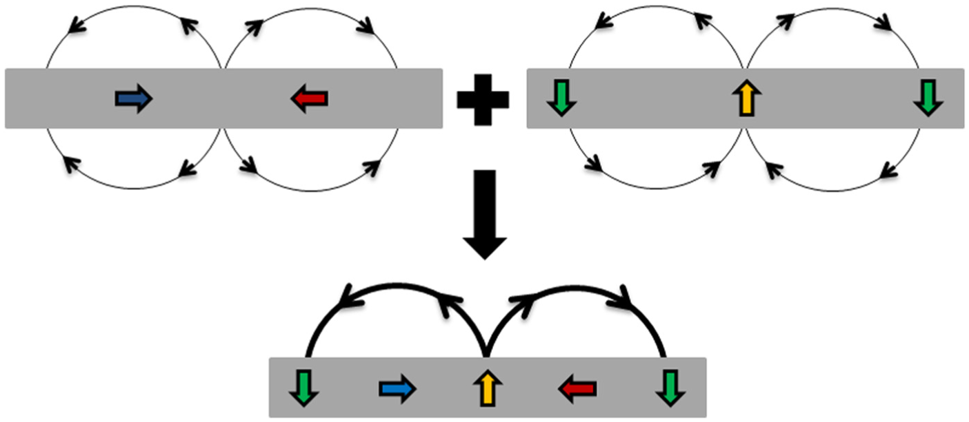
Principle of the Halbach array’s superposition.
Figure 4 shows the diagram of the energy conversion principle. The EMF is generated at the stator coil terminals as the slider vibrates by the walking and shaking motion of the user. The EMF is calculated by using Faraday’s law and can be expressed as follows
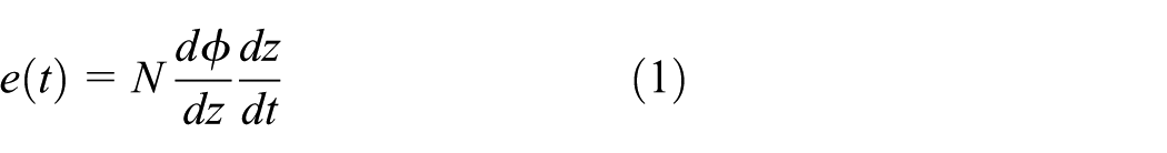
where N is the number of turns per coil,
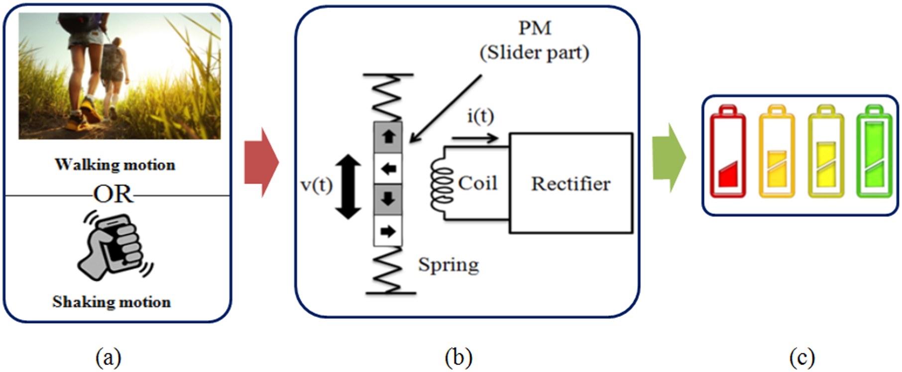
Diagram of energy conversion process: (a) User’s motion; (b) Energy conversion and (c) Charging battery.
Analysis of the linear generator and resonance phenomenon
Excitation from the user’s motion can be regarded as base excitation. Figure 5 shows a free-body diagram for the analysis, In Figure 5, m is the mass of the slider, k is the spring coefficient, and c is the coefficient of damping. The base excitation can be expressed by equation (2).


where

Free-body diagram for analysis of base excitation.
In walking motion, the displacement amplitude of the base excitation is less than 2 cm, which does not create enough for adequate induced voltage. To maximize the energy, the resonance is exploited by matching the motion frequency to the natural frequency of the generator. It is possible to check the displacement amplitude in accordance with the input frequency using equation (3), as shown in Figure 6.

Displacement amplitude according to input frequencies.
According to Figure 6, the vibration characteristics are different for each natural frequency. In walking or shaking motion (2–5 Hz), we confirmed that resonance occurs when the natural frequency (
Electromagnetic analysis of initial model of linear generator
In order to analyze the electromagnetic performance of the linear generator, finite element analysis is performed using the commercial electromagnetic software, Maxwell. Figure 7 shows the initial two-dimensional (2D) model with the cylindrical coordinates for the analysis. Also, the specifications of axisymmetric model which is the initial model of linear generator are summarized in Table 1. The total number of magnets in the linear generator is 32, the height of axial PM (
Initial model of linear generator on axial-symmetric view.
Specifications of initial model.
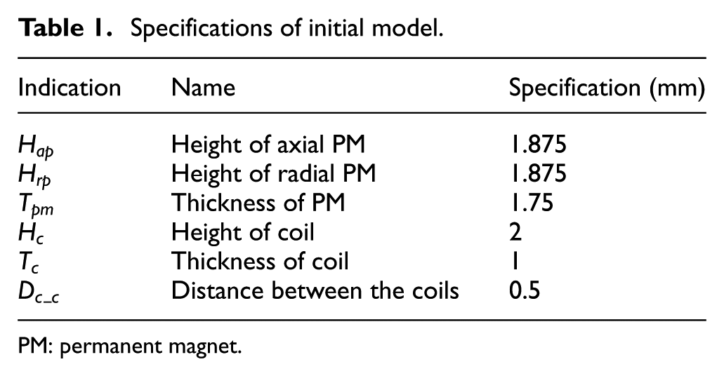
PM: permanent magnet.
The height of the coil is represented by the following equation

where the distance between the coils (
The number of coil turns is represented by the following equation
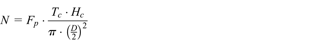
where the packing factor (
Initial model properties of linear generator.

Formulation of optimal design
Design variables and constraints
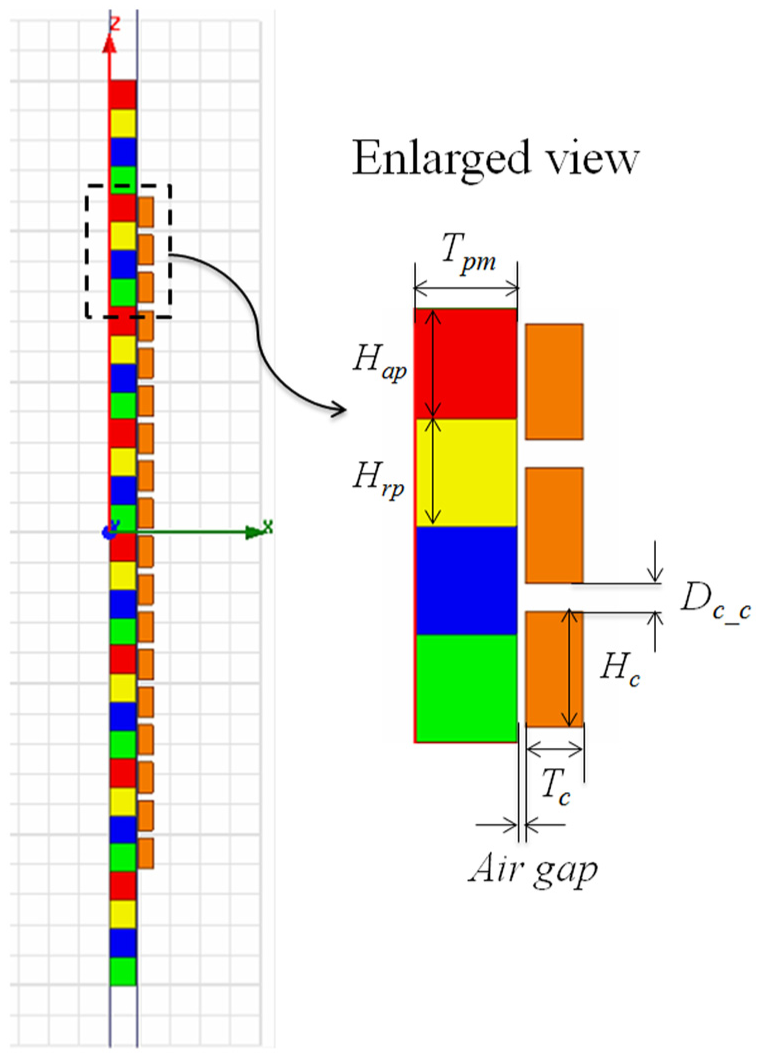
Figure 8 shows the design variables of the proposed Halbach array linear generator. We determined the following values:

Design variables for optimal design.
First, there is the limited length of the smartphone. In order to place inside the smartphone, the length of the linear generator is limited. The length of the linear generator is determined by the height of the PM. The axial magnetized PMs have the same height. Also, the radial magnetized PMs have the same axial height. Thus, the length of the linear generator, considering the total length of the 32 magnets except for the shaft is shown as follows.
The length of the linear generator must be less than 60 mm

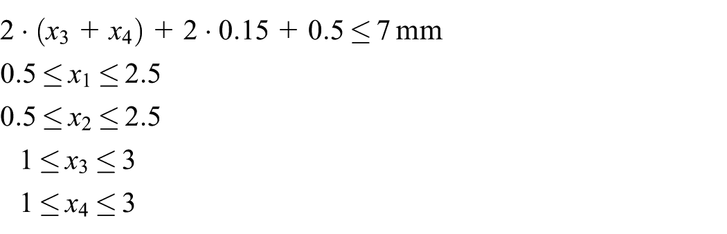
Second, there is the limited thickness of the smartphone. Thus, the thickness of the generator is limited to 7 mm, which is the maximum thickness of the smartphone. The diameter of the shaft and airgap is 0.5 and 0.15 mm, respectively.
The thickness of the linear generator must be less than 7 mm

Table 3 shows the initial, lower, and upper value of each design variable.
Design variables for optimal design.

PM: permanent magnet.
Design requirements
The generated electro-motive force should be maximized. This is represented by the following equation

Design formulation
The design problem for determining design variables that satisfy all design requirements can be formulated as follows
Find:
to maximize: induced voltage
subject to:
Analysis process and optimal design
Optimization was formulated in order to find the optimal values needed to maximize the induced voltage. We determined our design of experiments (DOE) using PIAnO (Process Integration, Automation, and Optimization), which is provided in the commercial software PIDO (Process Integration and Design Optimization). We performed electromagnetic analysis, and the induced voltage was determined using electromagnetic analysis software ANSYS Maxwell. Then, we selected the Kriging model and the evolution algorithm (EA) that is provided in PIAnO. Figure 9 shows the process of optimal design using PIAnO and ANSYS Maxwell.

Process of optimal design.
DOE
We determined the DOE using
Electromagnetic analysis
A total of 25 Halbach array linear generator models were created according to sampling points based on the DOE. Each model was analyzed using ANSYS Maxwell. Then, we created the approximate model. The electromagnetic analysis was processed manually. After the analysis, the design automation was processed using PIAnO.
Approximate model
The approximate model approximates relationship between the reaction value of the analysis model and the design variables. In this study, we determined the Kriging model. The Kriging model, a representative interpolation model, shows superb predictive performance under many design variables. Also, there are no parameters that depend on the experience and intuition of customers when choosing the design parameters because the Kriging model can optimize design parameters through maximum likelihood estimation (MLE). 17
Optimization method
We selected the EA based on the optimization method provided in PIAnO. Discrete variables can be treated efficiently and can be applied regardless of the function’s type because EA does not demand sensitivity of function. Although EA needs much more time than other optimization algorithms, it can be applied in our case because approximate model requires a short analysis time.
Results of optimization
In our results, all constraints including the length and thickness of the linear generator are satisfied. The induced voltage of optimal design compared with the initial design increases by 36%. We confirmed the design accuracy of the optimization result by actual analysis using Maxwell. Because the optimal design results can be changed based on using the metamodel instead of the actual analytical model in this research. 17 To do this, the Kriging model results (Opt_meta) of the optimal design variables and the analysis results from Maxwell (Opt_exact) were compared as shown in Figure 10. The Kriging model results (Opt_meta) and the Maxwell model results (Opt_exact) were similar. Therefore, we confirmed the high accuracy of the Kriging model’s prediction.

Comparison of the design accuracy.
We found the optimum value through the optimum design in limited range. Table 4 shows the initial and optimum values of the variables. As a result, the height of axial PM is decreased and radial PM is increased. Also, the number of the coil turns is increased by the thickness of coil. The maximum induced voltage generated in limited range. Table 5 shows the optimum properties of linear generator.
Initial and optimum value of design variables.

PM: permanent magnet.
Optimum model properties of linear generator.

Conclusion
In this study, we performed optimization for a Halbach array linear generator for a smartphone. We determined the DOE and performed electromagnetic analysis. Then, we selected a Kriging model and EA. We maximized the induced voltage of the existing Halbach array linear generator using an approximate model. The following conclusions were drawn from our results:
We formulated the design problem in order to maximize the induced voltage of the Halbach array linear generator;
We determined the DOE based on an orthogonal array using optimization software PIAnO. Then, each linear generator designed by sampling points was analyzed using ANSYS Maxwell. A Kriging model, provided in PIAnO, was generated based on the simulation results;
The optimal design was determined using the EA. All constraints were satisfied, and we obtained optimum values. The average of RMS-induced voltage was increased by 16% in comparison with the existing model (average RMS of induced voltage: 3.0 V)
Our optimization improves the efficiency to harvest the vibration energy during human walking, and the results show the possibility for the tubular linear electric generator suitable for the practical use in cellular phone.
Footnotes
Academic Editor: Yong Chen
Declaration of conflicting interests
The author(s) declared no potential conflicts of interest with respect to the research, authorship, and/or publication of this article.
Funding
The author(s) disclosed receipt of the following financial support for the research, authorship, and/or publication of this article: This research was financially supported by the Ministry of Trade, Industry and Energy (MOTIE) and Korea Institute for Advancement of Technology (KIAT) through the Research and Development for Regional Industry (R0004212).