
Abstract
The digital rod control system (DRCS) is an important component in nuclear power plants. Thus, the structural integrity of the isolation cabinet of the DRCS should be verified, considering the seismic loading and cooling performance of the heating source of electric equipment. In general, the structural safety and functionality of the DRCS are verified through ground excitation and flow experiments. Numerical structural analysis and CFD analysis provide preliminary assessments of dynamic behavior and temperature distribution of the cabinet in order to establish guidelines for designing experiments. This also reduces time, cost, and design cycles involved in the experimentation.
Response spectrum analysis was adopted in ANSYS for seismic analysis, which gives the peak response of the structure. The analysis was performed based on required response spectra (RRS), which envelop the floor response spectra (FRS). The maximum stresses are less than the allowable stresses, and the deflections meet the requirements. Electric equipment should operate within a limited temperature range for acceptable reliability. In the direct heat removal approach, six fans are installed as heat sink and air is forced through the heat sink by the fan. The cabinet and internal modules should be designed such that adequate ventilation with the fans is provided to maintain the temperature difference between the inside and outside within 5°C. Flow and thermal analyses were carried out by a CFD program, Icepak. As a result of this analysis, the number and the capacity were determined to meet the design requirement.
Introduction
According to a report of the Korea Energy Information Culture Agency, as of 2018, 449 nuclear reactors are under operation in 37 countries around the world. 1 In principle, the structures of nuclear power plants need to be more conservatively designed than other power plants so that they can be controlled during accidents. In most countries, including the U.S. and South Korea, nuclear power plants are designed in compliance with a safety code provided by a nuclear power agency.2,3
The nuclear power plant structure, system, and components specifies safety requirements, especially against earthquakes, which are a natural disaster. Each nuclear power plant is required to operate normally without outer-wall cracks or structural damage under seismic loads.4,5
Generally, the digital rod control system (DRCS) automatically controls fuel rods and consists of numerous circuits and electric devices.
If the DRCS does not operate normally, a serious accident may occur because the heat generated from the nuclear fuel in the nuclear power plant is not controlled. There are two reasons DRCS does not work properly. The first is the case of structural damage due to earthquake loads. The second is that electronic devices and circuits, which generate a large amount of heat are not sufficiently cooled, so they are damaged. Therefore, it is necessary to evaluate the structural integrity of the isolation cabinet controlling the DRCS under seismic and high-temperature conditions.
The objectives of this study are to evaluate the structural integrity of the DRSC by using the finite element method (FEM), and the thermal performance of fans by using the finite-volume method (FVM).
Analysis theory
Seismic analysis and design requirements
The response spectrum can be simply idealized using a single-degree-of-freedom structure that is subjected to damping and external loads, as expressed in equation (1). For a multi-degree-of freedom structural system under a seismic load, a relative displacement for the ground displacement can be obtained using equation (2).


where x, m, c, k, and
As shown in equation (3), the displacement vector {X(t)} can be expressed via the free-vibration mode matrix {Ø} and the corresponding time-variant function vector {q(t)} for each mode.

The maximum value of the coordinates in the general mode can be obtained using equation (4). Here, Sd is the maximum structural displacement, which is obtained from an input spectrum in a 1-degree-of-freedom-system with a natural frequency of ωi and modal damping ratio of (ζ), as shown in equation (5).
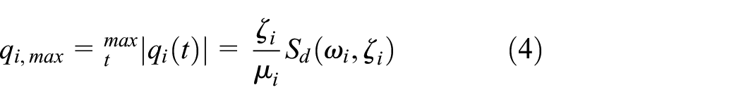

Figure 1 shows the required response spectra of safe shutdown earthquake (SSE) and operating basis earthquake (OBE) in both horizontal and vertical directions.6,7

Required response spectrum for isolation cabinet.
The structural integrity was evaluated using ANSYS, 8 a commercial finite element software program; the detailed procedure is presented in Figure 2.
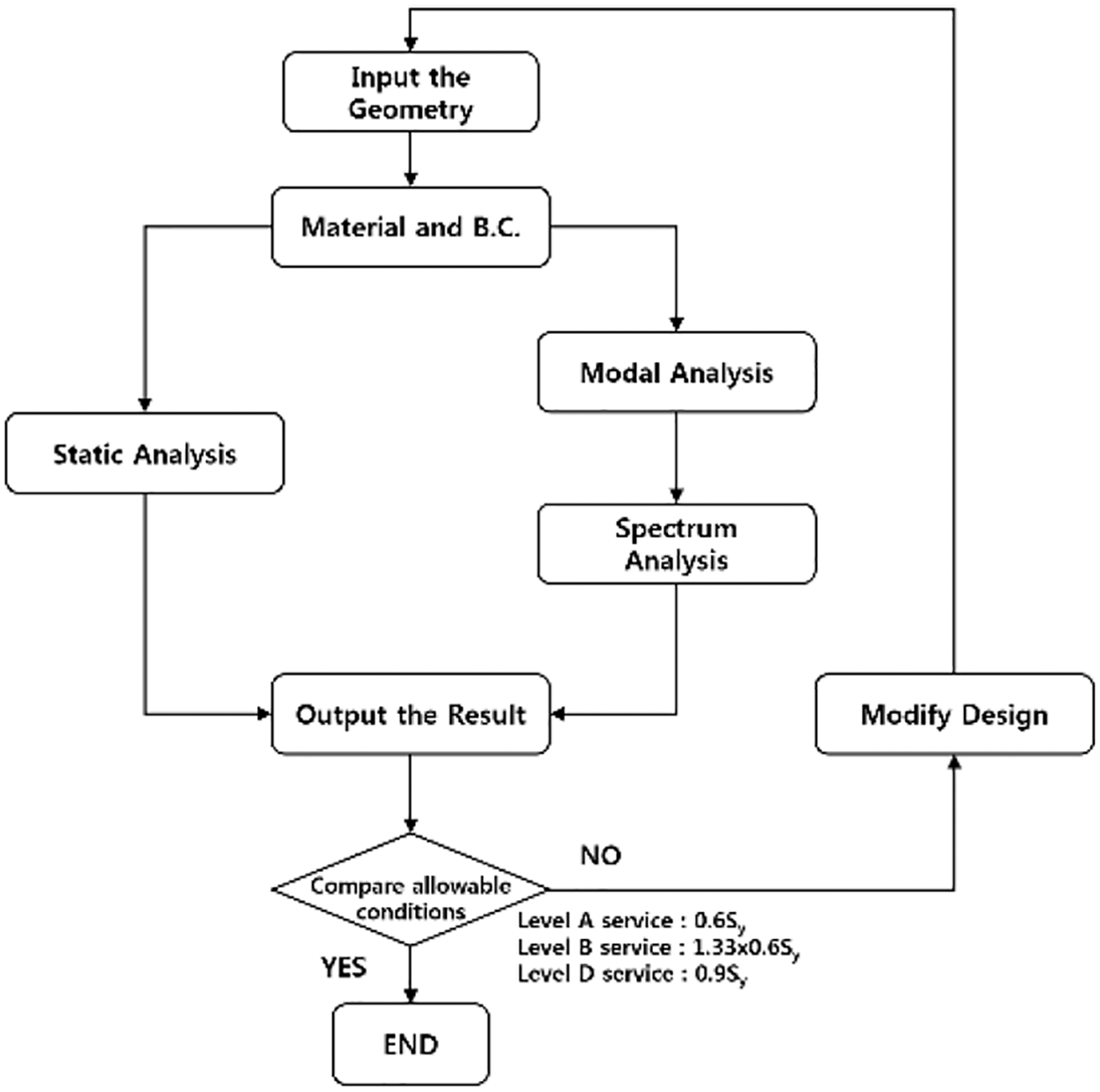
Procedure of response spectrum analysis.
Complex structures may possess a critical natural frequency mode at a higher frequency than that of the zero-period acceleration (ZPA). Thus, the missing mass method was used to efficiently and accurately calculate the effect of the mass that is missing (excluded) from the analysis. 9
Thermal fluid analysis and design requirements
The cooling performance of the cabinet was analyzed by using ICEPAK, ANSYS CFD, which are commercial programs.10,11 ICEPAK is an analysis program for analyzing electric devices and utilizes the finite-volume method (FVM). The Fluent-based solver and 12 million elements were used. The airflow was assumed to be an uncompressed steady flow. The governing equations of the model include the mass conservation equation, momentum equation, and energy conservation equation. The standard k-ε turbulence model was used as the fluid turbulence model.
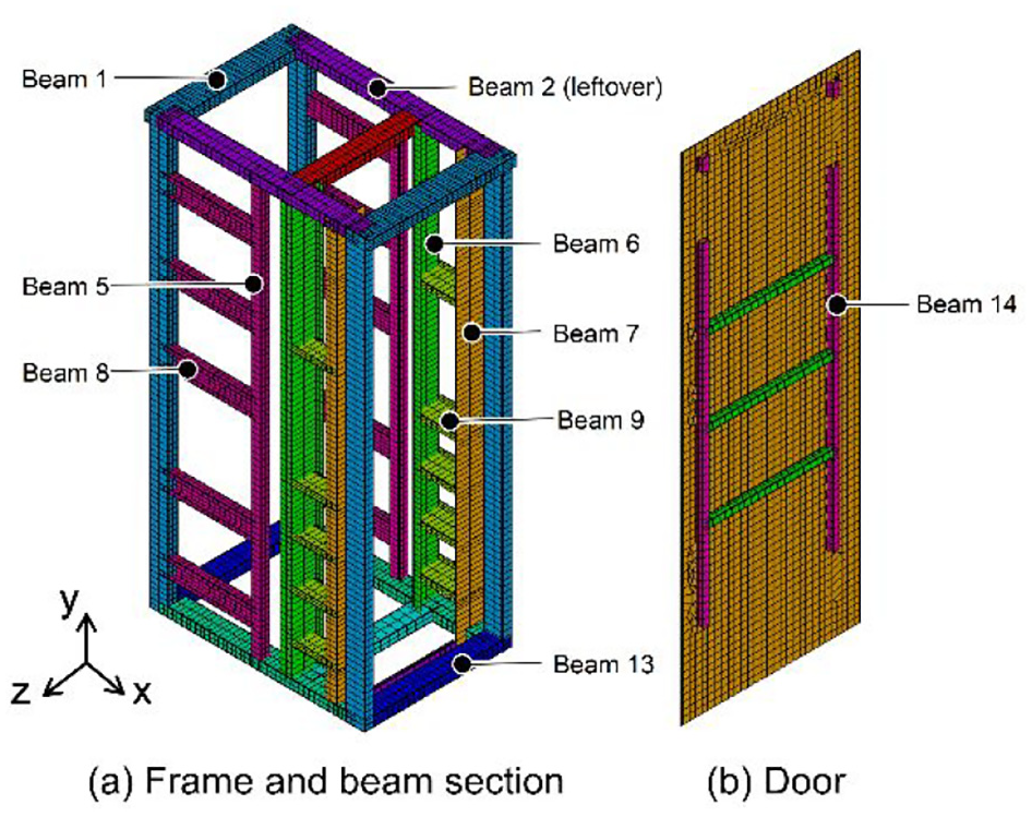
The isolation cabinet and the module were designed to ensure sufficient ventilation maintain the temperature difference between the outside and inside of the cabinet within 5°C with the door closed. A normal environmental temperature of 40°C should be applied for a conservative analysis. The cabinet was a rack-type cabinet with subracks. A majority of the electric devices were installed in the front part of the cabinet, and they generated considerable heat. The main components related to the electrical load of the cabinet were the power control center (PCC) for protecting electric devices and distributing power, power supply module (PSM), which converted AC power to DC power, supplied power, and controlled the output, maintenance and test panel (MTP), network switch, and diode component. Figure 3(a) illustrates the positions of these components.

Airflow and location of device.
The ventilation system had a total of seven doors (one front door, two back doors, and four roof doors). Six fans were used to cool the entire system by releasing heat. As shown in Figure 3(b), the air flowed from the bottom in the front part, where the electric devices were located, to the top
Shape and properties of DRCS cabinet
Figure 4 presents the actual shape and components of the cabinet, which had dimensions of 800 × 1220 × 2478 mm and a weight of 898 kg. The main components of the cabinet were the frames, plates covering the frames, two doors, and the base between the ground and the cabinet. Each plate had a thickness of 3.2 mm. The base was composed of two overlaid plates and had a thickness of 5.5 mm. The sections of the frames usually had rectangular and C shapes. Table 1 lists the material properties and allowable stress values. The properties and load conditions of each material and the allowable stress levels of SSE and OBE were set according to the ASME code.12,13

External structure of the isolation cabinet.
Material properties and allowable stress.

 According to ASME. NF (Linear elastic analysis).
Allowable stress for level A service (Normal) = 0.6Sy.
Allowable stress for level B service (Upset) = 1.33x 0.6Sy.
Allowable stress for level D service (Faulted) = 0.9Sy.
Structural analysis
Finite element model
The finite element model used 3D 2-node structural beam elements, 3D 4-node structural shell elements, and single-node mass elements (Figure 5).
FEM modeling of the cabinet.
The model was an integrated model assuming fully welded joints between the frames and the plates. The structures with lumped mass, such as the electric devices installed inside the cabinet, as well as the cables and the duct, which is irrelevant to the structural integrity, were expressed by mass elements (Figure 6).

Boundary conditions for analysis.
Result of structural analysis
Ideally, the sum of effective masses obtained in each direction needs to be equal to the total mass of the structure. However, in the case of a complex structure, since modes with low contribution factors are excluded, a minimum participating mass ratio of 90% is obtained in each direction. It is confirmed from Table 2 that the number of elements is sufficient. Table 3 presents the critical modes and participating mass ratios for the structure, of which the behavior is greatly affected by the participating mass ratio at a specific mode.
Result of mesh test.

Critical mode and modal participating mass ratio.

Table 4 shows the results for the main components of the isolation cabinet, namely the plate, frame, door, and base. The main parts of the cabinet under seismic load and inertia showed maximum stress levels under the SSE condition, as illustrated in Figure 7. The stress and displacement results of the cabinet revealed that the doors were vulnerable to seismic loads. The maximum stress and displacement were lower than the allowable stress and displacement, respectively. The integrity of the electric cabinet was evaluated based on this result.
Maximum stress and displacement of each part under each condition.


Maximum stress for each part in faulted condition.
Thermal fluid analysis
Finite volume model
Since the cooling performance was greatly affected by the flow in the cabinet, the model was created considering all shape information affecting the flow. Common electric devices were modularized in the program, and these modules are shown in Figure 8(a). As shown in Figure 8(b), ventilation was made in the slot where a door and electric devices were installed.

FVM modeling of the cabinet.
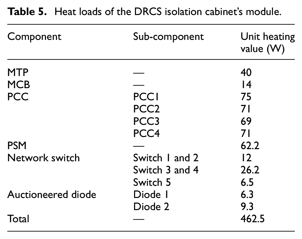
The heat sources having high heating values were equipped with heat sinks. Table 5 lists the heating values generated by each heat source. Three analysis cases are used to determine the number of fans causing flow. In Case 1, Case 2, and Case 3, the number of fans is six, five, and four respectively. A turbulent model was used to simulate the internal flow, and radiation was not considered.
Heat loads of the DRCS isolation cabinet’s module.
Result of thermal fluid analysis
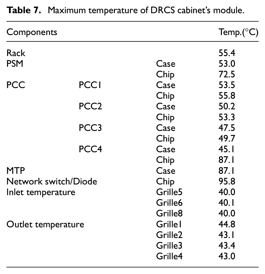
In Table 6, the heat balance for each analysis case is well satisfied, so the accuracy of numerical analysis can be confirmed. It is also found that if two fans failed, the design requirement that the average temperature increase at the outlet is 5°C or less is not satisfied. Table 7 and Figure 9(a) show the temperature distributions in Case 1. Velocity distribution and flow trajectory are shown in Figure 9(b) and (c) in Case 1.
Heat balance and temperature increase in analysis cases.

Maximum temperature of DRCS cabinet’s module.

Thermal fluid analysis results based on the fan axis.
Conclusion
A malfunction of the DRSC can cause a serious accident because the fuel rod cannot be controlled. The factors that cause the malfunction of the DRSC are caused by structural damage caused by an earthquake and overheating of an electric circuit or electric device.
This study established the verification and analysis procedure for the integrity of an isolation cabinet. For a seismic analysis, this study presents a method of simulating the behaviors of a real cabinet using a finite element model. The procedure and analysis method of a response spectrum design were established. In the seismic analysis, the isolation cabinet satisfied the allowable stresses.
Before the ventilation test, the temperature distribution is obtained by thermal fluid analysis. The cooling system using forced convection by fans should be satisfied the temperature range specified in the design requirements. It is also found that if two of the six fans failed, the design requirements were not satisfied. In this analysis, the electric devices are not modeled in detail in three dimensions, but are simply modeled with heating elements, so there is a limitation that the temperature distribution for each component cannot be accurately predicted.
Footnotes
Handling Editor: James Baldwin
Declaration of conflicting interests
The author(s) declared no potential conflicts of interest with respect to the research, authorship, and/or publication of this article.
Funding
The author(s) received no financial support for the research, authorship, and/or publication of this article.