
Abstract
The power-split hybrid electric vehicle (PS-HEV) has multiple working modes to maintain high operation efficiency according to different conditions. The main modes involved in the vehicle driving process are pure electric mode and the hybrid driving mode. Because the electromechanical coupling problem is involved in the above two working modes, the transmission system exhibits strong non-linear characteristics. If the operation range of the engine and motor are unreasonable, the rotor system will vibrate and become instability. In this paper, the non-linear dynamic equations of the electromechanical coupling of the transmission system are established for electric driving mode and hybrid driving mode. The closed-homoclinic phase trajectory equation at the center point of the disturbance-free Hamilton system is determined. The chaotic thresholds for the pure electric and hybrid driving modes are derived through the Melnikov’s method to obtain the optimal working domain of the engine and motor. Finally, numerical simulation analysis is conducted to verify the feasibility of the work domain optimization scheme. Simulation results show that the proposed engine and motor working area optimization scheme can effectively avoid the homoclinic bifurcation in the PS-HEV during the driving process and prevent the vehicle from entering the chaotic state.
Introduction
The configuration of the hybrid vehicle powertrain differs significantly from that of the traditional automobile. For the hybrid vehicle, there is electromechanical coupling between the motor and the load, as well as the motor and the engine during the power transmission process, which demonstrates strong nonlinear dynamics. One of the key challenges of hybrid electric vehicles is the electromechanical coupling due to multiple energy sources.1,2 If the operation range of the engine and motor are unreasonable, the rotor system will vibrate and become instability, even resulting in the shaft fracture of the power system. The nonlinear electromechanical coupling characteristics directly affect the performance, work efficiency, and safety of hybrid electric vehicles. Therefore, research on the dynamic characteristics and instability mechanism of hybrid systems has important theoretical significance on the system design and application.
With the development of the non-linear dynamics theory, non-linear characteristics of non-linear systems, such as vibration, instability, periodic solutions, bifurcations, and chaos, have become research hotspots. Hu et al. proposed an irregular internal excitation (engine excitation and motor excitation) and an external excitation (road excitation) would cause torsional vibrations of the transmission system. Besides, a simplified two-mass nonlinear dynamic model of a hybrid vehicle power system was established, and then applied to the prediction of the non-linear dynamics of the torsional instability range of the hybrid electric vehicle (HEV) powertrain. The analysis results were used to optimize the hybrid control strategy in order to improve the torsional stability of the hybrid vehicle power system under three typical driving modes. 3 The research on the torsional vibration of a hybrid vehicle power system mainly focused on the influence of the engine excitation, natural frequency analysis, and the corresponding modal analysis. Further, Hu et al. proposed a non-linear dynamic model of a hybrid power transmission system was established considering the multi-frequency excitation, and then the model was transformed into a fast-slow model with two-time scales. The De Moivre equation was introduced to unify the slow variables into a single variable, and the dynamic equations at different excitation frequencies and amplitudes were derived. Also, the bifurcation theory was used to study the bifurcation and stability analysis of the equilibrium point. Through the numerical analysis, the effects of the excitation frequency and amplitude on a dynamic behavior were studied using the equilibrium point curve, phase change phase diagram, and time history curve. The simulation results showed that the bifurcation would cause the jumping of the system trajectory and the corresponding blasting oscillation. With the continuous power and speed improvements, the electromechanical coupling effect became more and more prominent. 4 Zhou et al. studied the nonlinear dynamic characteristics of a system under the internal and external excitations were studied. The effects of the speed and load fluctuations on the system dynamic response were analyzed. The results showed that the increase in the excitation amplitude would cause the system to enter the chaotic motion through frequency doubling, and the speed change could effectively control system vibrations. 5 Liu et al. studied the dynamic characteristics of the gear transmission system under a multi-frequency excitation based on the Hopf bifurcation theory and revealed the unstable mathematical mechanism. The largest Lyapunov index revealed the influence of the system parameters, including the friction coefficient and modal damping, on the dynamic response from the table period to the unstable, chaotic motion. 6 Zhao et al. studied in-depth research on the torsional vibration of wind turbine transmission systems was conducted. By using the maximum Lyapunov exponent and Poincare interface, the effects of the internal and external incentives on the system dynamic response were studied. The results showed that the external excitation has the greatest influence on the system dynamic characteristics, and changes in the excitation amplitude led to the system chaotic motion. In addition, it was also found that various internal stimuli, such as stiffness and damping, could significantly change the system dynamic response.7–9 Bai et al. proposed a more comprehensive system model, including a nonlinear permeance network model (PNM), of a motor with a lateral torsion dynamic planetary gear system was established. The non-linear PNM considered the winding distribution of the motor, slotting of the stator and rotor, and non-linearity of the material. The lateral torsional dynamic planetary gear system considered the time-varying gear meshing stiffness, and the time-varying meshing and damping in the planetary gear system were studied in the proposed model. The simulation results were compared with the results predicted by the electromechanical model of a dynamic motor model with constant inductance. The results showed that the electromechanical coupling effect could cause additional severe vibration of the gear. In addition, it was found that external conditions, especially voltage transients, could have a significant impact on the dynamic characteristics of electromechanical systems. 10
Although the electromechanical coupling characteristics of the hybrid electric vehicle have been studied by many scholars, most of the studies focus on the influence of motor parameters, motor torque fluctuations, or engine torque fluctuations on the electromechanical coupling characteristics, or have only considered the electromechanical coupling process between the motor and the load. Namely, different working modes have been rarely included in studying the electromechanical coupling process between the motor and engine, and the motor and load. The chaotic phenomenon of the electromechanical coupling system was not considered during the mode switching coordination process. The main innovation of this paper is to analyze the system chaotic and bifurcation characteristics in pure electric mode and hybrid drive mode by establishing the electromechanical coupling torsional vibration model, so as to provide the basis for the torque distribution scheme during the mode switching of the PS-HEV. In the chaos analysis of the electromechanical coupling characteristics, the effects of different excitations, such as the engine, motor and the load, on the system are fully considered.
The remainder of this paper is organized as follows. Section I analyzes the configuration of the HEV powertrain and the corresponding working mode. Section II establishes the motor torque, engine torque models, and electromechanical coupling torsional vibration models of the power system in the pure electric and hybrid driving modes. Section IV analyzes the bifurcation and chaos thresholds of the two working modes, and Section IV determines the optimization scheme of the engine and motor operation area based on the chaos threshold. Section V conducts the numerical simulation analysis. Section VI concludes the paper.
The main contributions of this paper can be summarized as follows.
The nonlinear dynamic equations of the power split system for the pure electric and hybrid driving modes are established to demonstrate the system electromechanical coupling characteristics. The equilibrium point of the disturbance-free Hamilton system is determined and analyzed. The closeness of the disturbance-free Hamilton system at the center Homoclinic orbit phase trajectory equation is obtained.
By adding the disturbance term to the Hamilton system, the chaos thresholds for the pure electric and hybrid driving modes are determined with Melnikov method to obtain the optimization scheme of the working domains of the engine and motor.
PS-HEV structure
PS-HEV powertrain structure
The schematic diagram of the PS-HEV powertrain system studied in this paper is shown in Figure 1. The schematic diagram of the PS-HEV powertrain 11 studied in this paper is shown in Figure 2, where it can be seen that the transmission system consists of the engine, motor MG1, motor MG2, brakes CB1, CB2, and two planetary rows PG1 and PG2. The engine is connected to carrier C1, MG1 is connected to the sun gear S1, and MG2 is connected to the sun gear S2. In addition, the ring gear R1, carrier C2, and the output shaft are connected, and the ring gear R2 is fixed. Since the torque of MG1 can regulate the speed of the engine, the transmission in the power system is eliminated, leading to more compact configuration. The brakes CB1 and CB2 can control the engine and motor MG1, making them rotate freely or be fixed, and can also reduce the torque ripple of the engine and motor MG1.

The schematic diagram of a hybrid powertrains system.

The schematic diagram of hybrid power transmission system.
By controlling the working status of each power source and brake, the hybrid vehicle can switch between different working modes. According to the working status of the power source and the brake, eight working modes of the hybrid vehicle can be realized: electric driving mode, compound pure electric driving mode with MG1 and MG2, engine starting mode, hybrid driving mode, charging while standstill mode, compound braking mode, mechanical braking mode and stopping mode. Among them, the switching process from electric driving mode to hybrid driving mode involves various intermediate states such as engine startup and speed regulation. Compared with other driving mode switching, it is more complicated, as shown in Table 1.
Mode division of power split hybrid electric vehicles.

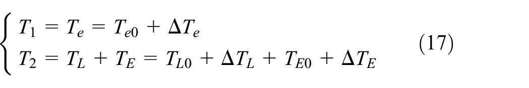
The electromechanical coupling of the transmission system in the pure electric mode includes mainly the coupling between motor MG2 and load. On the other hand, the electromechanical coupling of the transmission system in the hybrid driving mode includes mainly the coupling between motor MG2, engine, and load.
Therefore, the nonlinear dynamics of an electromechanical coupling system that are studied in this paper are as follows: (1) the nonlinear torsional vibrations caused by the electromechanical coupling between motor MG2 and load; (2) the nonlinear torsional vibrations caused by the electromechanical coupling between motor MG2, engine, and load.
Electromechanical coupling torsional vibration model of power system
Electromagnetic torque model of permanent magnet synchronous motor
In order to simplify the analysis, the following assumptions are made12,13:
(1) The winding current changes with the time according to the cosine law, and the windings are star-connected; (2) the rotor is cylindrical, and the air gap is uniform; (3) the rotating air gap magnetic field ignores the effects of higher harmonics; and (4) the motor loss is neglected.
When the coil has the alternating current that changes with the cosine law, and the influence of harmonics is not considered, according to the theory of electrical machinery, the magnetomotive force of the three-phase symmetrical stator winding is expressed as12,14:

where
The magnetomotive force of the rotor is given by:

where
The air-gap magnetic field energy of a permanent magnet synchronous motor is given by:
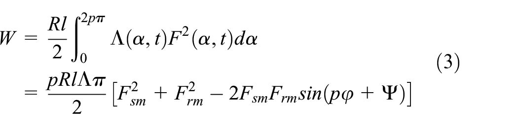
where R denotes an average radius of the air gap, and
By considering the torsional vibration angle of the PMSG, the rotor synthesis fundamental wave magnetomotive force can be expressed as:

If the rotor torsional angle is denoted as

where
The simplified equation of the electromagnetic torque for the PMSG can be obtained by Taylor approximation.

where
Engine shaft torque model
The unbalanced torque the engine is mainly composed of the reciprocating moment of inertia
where
Since the fourth- and higher-order unbalanced moments account for only 2.5% of that of the second-order, only the second-order unbalanced torque is considered and given by:

Where
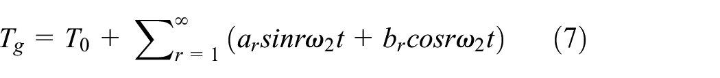
The cosine component of the combustion gas moment

where
Torsional vibration model
Gear pair dynamics model
In order to study the electromechanical coupling characteristics of the PS-HEV powertrain, the dynamical model of the planetary gear is introduced and shown in Figure 3.

The planetary gear dynamics model.
The general equation of the pure torsional dynamics of the planetary gears dynamics model that is presented in Figure 3 is as follows. 17
For the sun wheel:

where
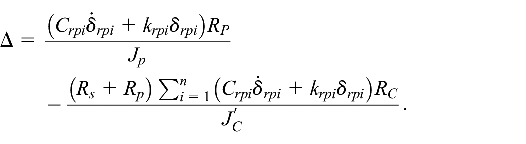
For planetary wheels:
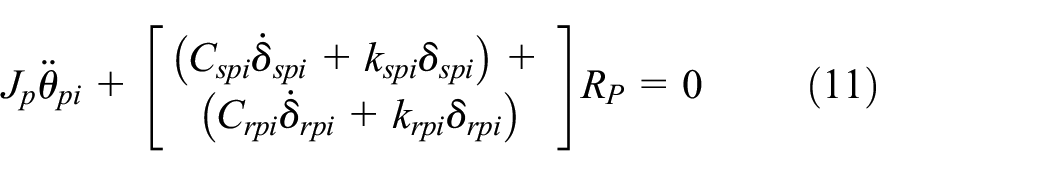
where
For the planet carrier:

where
Also,

where
Nonlinear model of electromechanical coupling rotor in electric driving mode
According to the torsional vibration model of the gear pair given by equations (10)–(12) the electromechanical coupled torsional vibration model at the pure electric mode is established, 18 and it is given by:

where
According to the torsional vibration equation of the gear pair, equation (14) can be substituted into equations (10)–(12), we have:

New variables are set to

where
Also,
Nonlinear model of electromechanical coupling rotor in hybrid driving mode
According to the torsional vibration model of the gear pair given by equations (10)–(12) the electromechanical coupled torsional vibration model at the hybrid driving mode is established, 3 and it is expressed as:
where
According to the torsional vibration equation of the gear pair, equation (17) can be substituted into equations (10)–(12) which results in the following relations:

New variables are set to

where
Work area optimization based on global bifurcation and chaos threshold
Equilibrium point analysis of undisturbed Hamilton system
The excitations of the engine and load input, and the engine damping terms are regarded as disturbance. Equations (16) and (19) are respectively rewritten as the form of the state equations19,20:


where
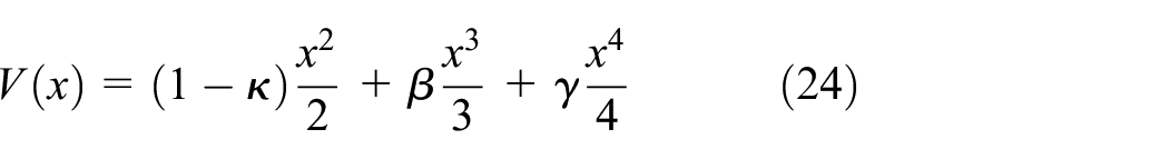
The potential function of the undisturbed system has an important on studying different nonlinear dynamic behaviors. Therefore, it is necessary to study the function of the undisturbed system in conducting electromechanical coupled nonlinear dynamics. When

It should be noted that by discarding the damping and harmonic excitation terms, the transmission system can be converted into a Hamiltonian system. The two working modes have the same Hamilton form, and the properties of their equilibrium points are also the same. The Hamiltonian function is given by:

And the asymmetric potential energy is expressed as:
Let
Where:
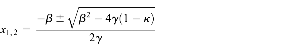
Then, the equilibrium point and its stability are analyzed according to the conditions of the system parameters
If
If
The stability of the equilibrium point of the undisturbed Hamilton system is as follows:
(A)
Case A1: if
Case A2: if
There exit no homoclinic or heteroclinic orbit.
(B)
(1) Case B1: if
There exit the trajectory to intersect the homoclinic orbit.
(2) Case B2: if
There exit heteroclinic orbit in the response of an unperturbed system.
(C)
(1) Case C1: if
There exit the trajectory to intersect the homoclinic orbit.
(2) Case C2: if
There exit heteroclinic orbit in the response of an unperturbed system.
Based on the parameters given in Table 2,
Main parameters of a hybrid powertrain.


The potential function and phase trajectory of an undisturbed Hamilton system.
In this case,

When

Thus, the equations of x and y can be obtained, that is, the phase trajectory equations of the homoclinic orbit of the Hamilton system, and they are as follows:

Chaos threshold determination
According to the above analysis, the undisturbed Hamilton system transformed by the PS-HEV powertrain has the homoclinic orbits, and the PS-HEV transmission system has uncertain disturbances. When the disturbance terms is added to the Hamilton system, the closed homoclinic orbit is destroyed, which will lead to the same-direction unfolding bifurcation The existence of global homoclinic bifurcation often indicates the chaotic motion. Therefore, Melnikov method can be used to estimate the parameter space that the homoclinic bifurcation may be transformed into the chaos. In this way, the threshold of chaotic motion of the system can be determined.
The essence of the Melnikov method is to calculate the distance between the stable and unstable manifolds after the disturbance of the homoclinic orbit of the undisturbed Hamilton system. Determine whether the stable and unstable orbits meet the conditions of cross-section intersection. Based on the given threshold conditions for the chaotic vibration of electromechanical coupling to determine whether there is chaos in the system.21,22
Since the disturbance terms for the pure electric and hybrid driving modes are different, the Melnikov analysis needs to be performed separately for these two working modes.
Melnikov analysis of electric driving mode
equation (20) can be transformed into:

where
According to Melnikov’s principle, the distance between stable and unstable manifolds can be expressed by the Melnikov equation,23,24 as follows:
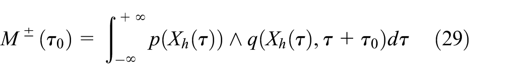
where
By substituting equation (28) into equation (29), the Melnikov integral is obtained as:

where
The first integral
According to the Melnikov theory, if

Assuming
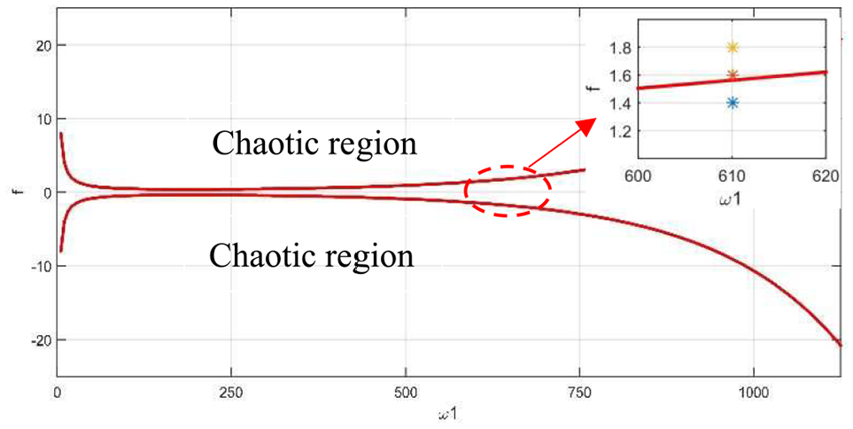
Threshold curve of the homoclinic bifurcation (
Melnikov analysis of hybrid driving mode
Assume

where
According to Melnikov’s principle, the distance between stable and unstable manifolds can be expressed by the Melnikov equation as follows:

where
By substituting equation (29) into equation (30), the Melnikov integral is given by:

Where
Similarly, the first integral
According to the Melnikov theory, if
Assume

The threshold curve of homoclinic bifurcation (
Assume

The threshold curve of homoclinic bifurcation (
Engine and motor working area optimization scheme
According to the Melnikov analysis of the PS-HEV powertrain in pure electric and hybrid driving modes, the optimization scheme of the engine and motor working domain based on the global bifurcation and chaos threshold is designed. It is assumed that the load excitation is 120
In the pure electric mode, the speed of motor MG2 and the corresponding working torque are 5830
In the hybrid driving mode, the speed of motor MG2 and the corresponding working torque needed to ensure that the chaos does not appear are 6800
In summary, when the vehicle is operating in the pure electric mode, MG2 provides the driving torque to drive the vehicle. The torque of MG2 is smaller than 74
Numerical simulation verification
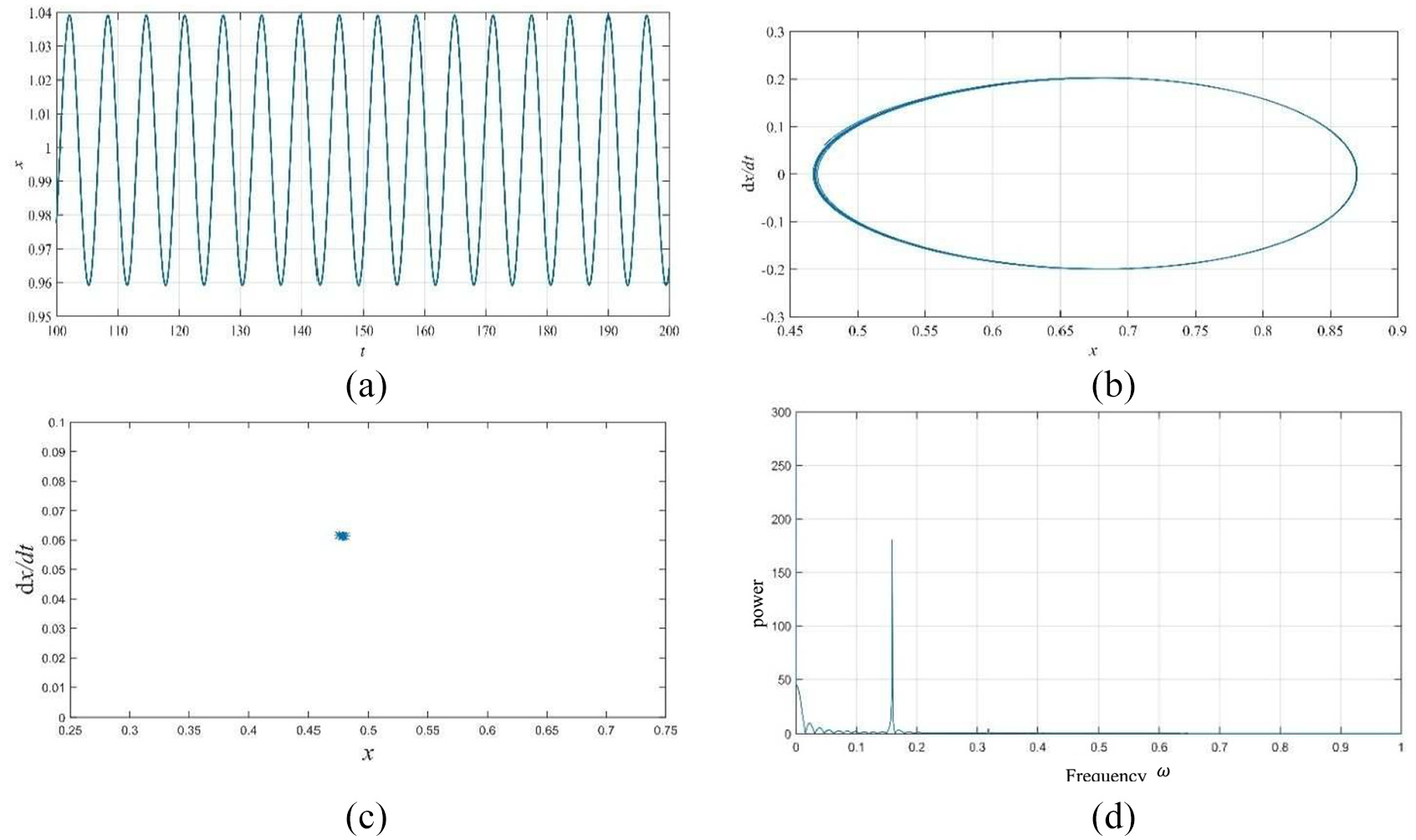
In order to verify the accuracy of the results obtained by the above-mentioned Melnikov analysis, Runge-Kutta method is used to verify the torsional vibration equations (20) and (21) of the transmission system. The calculated time response history curve (excluding the transient instability part at the beginning of the simulation), phase trajectory diagram, Poincare section diagram and amplitude spectrum are analyzed.
The purpose of the numerical simulation is to verify the effectiveness of the proposed work area optimization scheme.
Numerical analysis of electric driving mode
When

The numerical simulation results at
When

The numerical simulation results at
The numerical simulation analysis results show that in pure electric mode, the torque of MG2 was
Numerical analysis of hybrid driving mode
The numerical simulation results at
When

The numerical simulation results at
The numerical simulation analysis results showed that in the hybrid driving mode, the torque of motor MG2 was
Conclusion
In this paper, a PS-HEV is studied, and its two working modes that are involved in the mode switching process are analyzed. Also, the bifurcation and chaos characteristics of the hybrid vehicle transmission system are studied in different working modes, and the electric driving mode and hybrid driving mode are analyzed by Melnikov’s method. In addition, based on the chaos threshold, the working domain optimization scheme of the engine and motor is obtained. Finally, numerical simulation analysis is used to verify the feasibility of the work area optimization scheme.
By studying an undisturbed Hamilton system corresponding to the electromechanical coupling nonlinear equation of a transmission system, by analyzing the equilibrium point characteristics of a system, and by solving the undisturbed Hamilton system potential function and phase trajectory, it is concluded that the system has a closed orbit at the center point, and homoclinic exists. In orbit, when the Hamilton system experiences the external interference, the homoclinic orbit is split by disturbance, and the system produces homoclinic bifurcation, which causes the chaos.
Due to the uncertain disturbances of a PS-HEV transmission system, when the disturbance term is added to the Hamilton system, the closed homoclinic orbit is destroyed, resulting in the global homoclinic bifurcation and chaotic motion. The homoclinic can be estimated by Melnikov’s method, and the bifurcation may be transformed into a parameter space of chaos so that the threshold of the chaotic motion of the torsional vibration of electromechanical coupling can be determined. In the pure electric mode, in order to ensure the stability of the transmission system without bifurcation and chaotic motion, the torque of motor MG2 should be
However, there are still some shortcomings that need to be addressed. For instance, a simplified construction of the transmission system mode should be obtained, and the internal motor parameters, the number of pole pairs of the motor, the magnetic circuit saturation coefficient, and other electromagnetic characteristics should also be considered.
Footnotes
Handling Editor: James Baldwin
Declaration of conflicting interests
The author(s) declared no potential conflicts of interest with respect to the research, authorship, and/or publication of this article.
Funding
The author(s) disclosed receipt of the following financial support for the research, authorship, and/or publication of this article: This work has been supported by the National Key Research and Development Program of China (2018YFB0105000 and 2017YFB0102603), National Natural Science Foundation of China (51875255, 61601203, 61773184, U1564201, U1664258, U1764257 and U1762264), Natural Science Foundation of Jiangsu Province (BK20180100), Six Talent Peaks Project of Jiangsu Province (2018-TD-GDZB-022), Key Project for the Development of Strategic Emerging Industries of Jiangsu Province (2016-1094), Key Research and Development Program of Zhenjiang City (GY2017006), National Natural Science Foundation of China (Grant No. 51905219), Natural Science Founding of Jiangsu Province (Grant No. BK20190844), and Natural Science Research Project of Jiangsu Higher Education Institutions (Grant No. 19KJB580001).