
Abstract
The aim of this study is to optimize the characteristic parameters of the segmental joints based on the contact pressure of sealing gasket. The design status of shield tunnel segment joint sealing gasket material, cross-section type, and holes arrangement through statistical data are first analyzed using the numerical simulation method. The result of this study indicates that the linear regression analysis of the outer contour parameters of the gasket was carried out using the bottom edge length of the gasket as the control variable in accordance with the statistical samples, and the influence of geometric parameters on the waterproofing design of sealing gasket is analyzed by numerical simulation from the aspects of the number of closed holes, the shape of closed holes, and the change of the opening rate in different parts. Characteristic parameters optimization of rubber hardness parameters on waterproof design of sealing gaskets have been completed on the contact pressure of sealing gasket for segmental joints. It provided some references for the design, production, processing, and quality inspection of shield tunnel gasket in the future.
Keywords
Introduction
With the rapid development of tunneling construction all over the world, shield construction method has been widely adopted in a great number of infrastructures such as highways, railways, under-river tunnels, and subway systems due to its safety and efficiency.1,2 Because the shield tunnel lining adopts the assembled segment structure, a number of joints exist in the tunnel. At present, the waterproofing of shield tunnel joints is mostly achieved by the frame rubber nested in the grooves of the segments. Water leakage is all along one of the potential problems of underground structures.3–6 It has become a topical issue for segmental joints of shield tunnels during the construction and the operation stages. However, characteristic parameters of sealing gasket in shield tunnels have been seldom obtained. To meet the increasing water pressure, opening and malposition of segment joints, and the increasingly complex section structure of sealing gaskets, ethylene propylene diene monomer (EPDM rubber) material has become the mainstream.7–10 A series of research works on the waterproofing design of sealing gasket segment joints have been carried out.4,11–13 For instance, Tuo et al. 14 studied the design of ultra-high water pressure shield tunnel sealing gasket by physical test, and analyzed the waterproofing performance of several section forms. Z Ming et al. 15 conducted compression test and waterproofing test to study the sealing gasket form of high water pressure tunnels in Shanghai. S Lianwei 16 combined with the segment joints waterproofing project of Hangzhou Metro Line 1 and analyzed the mechanism of lateral water pressure on sealing gasket. W Ding et al. 12 studied the waterproofing design of shield tunnel sealing gasket on Weisan Road in Nanjing. C Gong and Ding 4 obtained a calculation formula for contact pressure and water pressure of sealing gaskets by combining test and numerical analyses data. The influence of geometric sizes change caused by production technology on waterproofing was analyzed by ZY Lei and Liu 17 Based on the specific project, K Xiang and Shi 18 adopted ANSYS numerical simulation method to optimize the design of sealing gasket section.
However, the aforementioned research is mostly based on the specific projects for limited sealing gasket section optimization studies. Research on the characteristic parameters optimization based on contact pressure of the shield tunnel sealing gasket is quite scarce, and the relevant national norms 19 alone specifically point out that the gasket groove should be greater than or equal to the sectional area of gasket for gasket design. Therefore, it is necessary to study the characteristic parameters optimization of sealing gasket to prevent from seepage. Based on this, the article first analyzed the characteristic parameters status of sealing gasket from China through statistical data. On this basis, the influence of section geometric parameters and rubber hardness parameters on contact pressure of sealing gasket are analyzed by the numerical simulation. The purpose is to provide some references for the design of shield tunnel sealing gasket in the future.
Statistical analysis of the sealing gasket status
To analyze the characteristic parameters of shield tunnel sealing gasket from China, the section data of shield tunnel sealing gasket from China were collected based on literature and project cases, and a total of 34 section samples of sealing gasket were collected.
Analysis of sealing gasket types
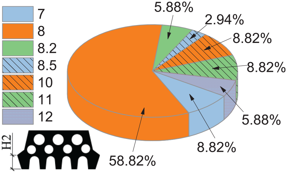
According to the statistical samples, the gasket material in China mainly uses EPDM elastic rubber. A few projects with higher waterproofing requirements adopt composite gaskets, as shown in Figure 1(a). The elastic gasket accounts for 70.59%, while the composite gasket accounts for 29.41%. The elastic gasket materials also include nitrile butadiene rubber (NBR) and chloroprene rubber (CR), which are widely used in assembled tunnels in Europe and America, because of the small price difference between CR and EPDM. 1 The section of the “Sheffield” sealing gasket is designed as a porous structure, consisting of closed holes and open holes. The form of the open holes is similar to the “straight wall top arch section” in tunnel engineering. From the statistical literature,2,4,6,10,12,15,17,18,20 the form is almost unchanged. However, there are many forms of the closed holes, as shown in Figure 1(b). The shapes of the closed holes include circle, semicircle, and triangle (chamfering). The number of circular holes is a maximum of 20 accounting for 58.82% of the total, the closed holes of triangle (chamfering) account for 35.29%, and the semicircular closed holes account for the least number of 5.88%. Circular holes are often used in the closed-hole sections, because circular holes can effectively reduce local stress concentration and reduce the relaxation effect caused by the stress concentration of sealing gasket. The arrangement of closed holes has a great influence on the waterproofing performance of gasket. Statistics show that the double-row closed holes are adopted by most section designs. It can be seen from Figure 1(c) that the double-row closed holes account for 73.33% of the total, while the sealing gaskets with single-row closed holes only account for 26.67% of the total. In the statistics data, the closed holes of four sections included “three-row,” but the area of closed holes was set in the area of open holes. For such sections, they were not divided into the single-row holes or the double-row holes. To sum up, it can be concluded that the most commonly used shield sealing gasket in China is: EPDM, “Sheffield” elastic rubber sealing gasket, whose closed holes are mostly of circular double-row holes structure.

Statistical analysis results of gaskets: (a) type of sealing gaskets, (b) shape of closed holes, and (c) number of closed holes rows.
Linear regression analysis of geometric parameters
In general, for the geometric parameters of the inner holes of the gasket, the specific data of the sample data are not published. Therefore, only the parameters of outer contour of sealing gasket can be counted in this study. According to the statistical data, five parameters are mainly included: top edge S1, bottom edge S2, gasket width S3, gasket thickness H1, and shoulder height H2. The specific meanings are shown in Figure 2.

Implication of geometric parameters of seal gaskets.
To study the law of the outer contour parameters of the gasket, the bottom edge S2 was taken as the independent variable, and the top edge S1, the gasket width S3, the gasket thickness H1, and the shoulder height H2 were taken as the dependent variables. The statistical section data were visualized and obtained in Figure 3. At the same time, a linear fitting process was performed on the obtained scatter plot to obtain the linear function relationship of the top edge S1, the gasket width S3, the gasket thickness H1, the shoulder height H2, and the bottom edge S2 as the independent variable, as shown in Table 1.

Regression analysis of geometric parameters of outer contour of seal gasket: (a) scatter plot of the bottom edge S2 and the top edge S1, (b) scatter plot of the bottom edge S2 and the gasket width S3, (c) scatter plot of the bottom edge S2 and the shoulder height H2, and (d) scatter plot of the bottom edge S2 and the gasket thickness H1.
Fitting curve parameters and fitting degree of outer contour size data of seal gasket.

It can be seen from Table 1 that the fit degree of the gasket width S3 is the best, and the R value of determination coefficient is 0.8817. The R value of the determination coefficients of the top edge S1 and the gasket thickness H1 are 0.6985 and 0.7856, respectively, showing a better correlation with the bottom edge S2. However, the R value of determination coefficient after fitting of the shoulder height H2 is only 0.0125, indicating a low correlation between shoulder height H2 and the bottom edge S2.
The shoulder height H2 data of 34 sections were collated to obtain Figure 3. It can be seen that there are seven size parameters of the shoulder height H2, among which the mode is 8 mm and there are 20 sections, accounting for 58.82% of the total. The other six size parameters contain only 1–3 sections. At the same time, it is noted that the scatter plot has obvious regional distribution characteristics. Taking the scatter plot of the bottom edge S2 and the top edge S1 in Figure 3(a) as an example, it can be found that the gasket has three aggregation areas, as shown in circle in Figure 3(a). It can be found that the three aggregation areas roughly correspond to the axis of S2 = 32.5 mm, S2 = 37.5 mm, and S2 = 45 mm on the X axis (the gray dotted lines in the figure). Analysis of Figure 3(b)–(d) shows the same law characteristic. The reasons for this characteristic may be related to the size of the tunnel segment and the waterproof pressure, but unfortunately there is a lack of relevant information in the data.
Influence analysis of closed holes form
The analysis of sealing gasket types shows that the open holes form of the “Sheffield” sealing gasket is almost unchanged, while the closed holes form contains more types. In this section, numerical simulation method will be used to analyze the influence of closed holes on the waterproof effect of gasket from two aspects of the number of holes rows and the holes shape, see Figure 4. The method introduced in Li et al. 7 for determining the rubber constitutive model and parameters in numerical simulation.
Distribution of shoulder height parameters of sealing gasket.
Number of closed holes rows
According to the statistical analysis in the preceding section, at present, the closed holes of elastic gasket in China are mainly circular, and the holes arrangements mainly include single-row holes, double-row holes, and even “three-row” holes. The waterproof performance of these holes arrangements will be the focus of this section. Yan Q et al. 11 compared and analyzed the arrangement of sealing gasket holes by studying the compression performance of the gasket (load–deformation curve). He proposed that the best way to arrange holes with waterproof performance should be single-row holes, and the staggered holes are better than the aligned holes. This study will analyze the influence of closed-holes arrangement on the waterproofing of the gasket from the perspective of average contact pressure. The calculation method of average contact pressure is adopted in the literature. 11 The curve drawn by contact pressure is integrated, and the integral result divided by the length of the contact surface is the average contact pressure. From the statistical analysis of the geometric parameters of the sealing gasket, the closed holes of the “Sheffield” sealing gasket are basically distributed in a rectangular area of 40 mm × 0 mm (length × height), so the model size in this section is 40 mm × 10 mm (length × height). The geometric relationship of the closed holes model is shown in Figure 5, where Figure 5(a) is the arrangement of the aligned holes and Figure 5(b) is the arrangement of the staggered holes.

Analysis model of closed holes arrangement: (a) arrangement of the aligned holes and (b) arrangement of the staggered holes.
The meanings of model parameters are as follows: the radius of the closed holes is R, the spacing of the holes (the distance between the outer contours of the two holes) is 2H, and the margin of the holes (the distance between the outer contour of the closed holes and the boundary of the model) is H. If the number of holes in the horizontal direction is N, it can be obtained from the geometric relationship: one row of holes contains four holes, two rows of holes contain 16 holes, three rows of holes contain 36 holes, and four rows of holes contain 64 holes. Among them, the arrangement of the aligned holes and the staggered holes can be distinguished when it is more than two rows. Although the holes analyzed here are closed, a small number of open holes appeared when the staggered holes arrangement is restricted by the model, as shown in Figure 5(b).
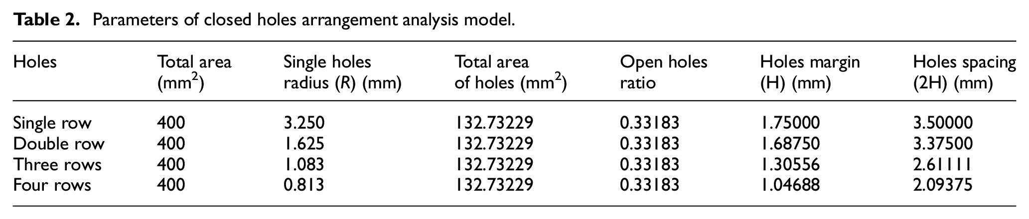
This section only analyzes the geometric parameters, so the hardness of rubber is 65°. At the same time, the opening rate of the geometric model is the same, that is, the net area of the rubber is the same. When the single-row closed holes radius is determined to be 3.25 mm, the holes opening rate is calculated to be 0.33183, and the specific parameters of the holes radius of other arrangements are obtained from the geometric relationship, as shown in Table 2.
Parameters of closed holes arrangement analysis model.
After processing the analysis results, Figure 6 is obtained. It can be seen that the average contact pressure data curves of the other six conditions, except the single-row holes, all show an inflection point with the increase of compression distance. The inflection points of the double-row holes and the four-row staggered holes appear when the compression distance is 2.0 mm; the inflection points of the three-row holes and the four-row aligned holes appear when the compression distance is 1.5 mm. The reason for this phenomenon is that the single-row holes do not have closed holes instability within the range of 3 mm compression, while the other six types all have closed holes instability.

Effect of closed holes arrangement on average contact pressure.
It can be seen from Figure 6 that the average contact pressure is the highest when the single-row holes are fully compressed, and the single-row holes seem to be the best waterproofing design according to the waterproof mechanism. However, based on the relationship between the assembly force and the average contact pressure, a higher average contact pressure is required to match the corresponding assembly force. Obviously, the assembly force of a single row of holes is larger than that of other holes arrangements.
The “Sheffield” elastic sealing gasket is widely used because of its load–displacement characteristic curve has an area where the compression quantity changes and the compressive stress are basically unchanged. The characteristics can make the segment, which is under a certain opening for some reasons (such as earthquake, assembling error, etc.) still guarantee waterproofing performance. 12 When the compressive stress is changed to the average contact pressure, it is shown that the compressive amount is changed while the average contact pressure is basically unchanged. According to this theory, the optimal arrangement of closed holes should be the a four-row staggered holes, because the average contact pressure hardly changes with the compression amount after the compression distance is greater than 2.0 mm. However, the closed holes radius is only 0.813 mm, the number of holes reaches 64, and the holes spacing reaches 2.09375 mm. Obviously, it is not easy to process such a small structure. At the same time, there is an area where the compression amount changes and the average contact pressure are basically unchanged after the inflection point of the three-row holes and the double-row holes. To sum up, according to the average contact pressure evaluation index, considering the waterproof effect and the realization of production and processing, the double-row holes should be preferred for the arrangement of closed holes. The conclusion also explains the mechanism of double-row holes in the closed holes in the anterior segment statistical analysis.
Shape of closed holes
Through the statistical analysis of the previous section,2,3,6,8,12,14,18,20 it can be concluded that the holes of sealing gasket mainly includes full circle, triangle (chamfering), and semicircle. It is also concluded that the holes arrangement of sealing gasket is best with double-row holes. This section will combine the above two conclusions to analyze the influence of the closed holes shape on the waterproof performance of the sealing gasket.
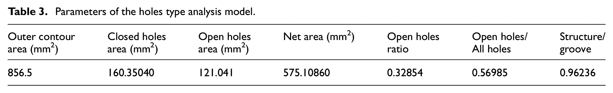
As shown in Figure 7, there are four sections, where Figure 7(a) is semicircular aligned holes, Figure 7(b) is circular aligned holes, Figure 7(c) is circular staggered holes, and Figure 7(d) is triangular staggered holes. The shapes and sizes of closed holes of each type contained in each section are the same. For example, the triangular closed holes in the triangle (chamfered) section are the same. In addition, other shapes are included in the semicircular aligned holes and circular aligned holes sections due to the limitation of geometric profile and opening rate. In this section, the hardness of rubber is 65° and the opening rate of the sealing gasket, the outer contour, and the open holes are all the same. The dimensions of the outer contour of the gasket are shown in Figure 7(a), and the specific parameters of each section are shown in Table 3.

Holes type analysis model and parameters: (a) semicircular aligned holes, (b) circular aligned holes, (c) circular staggered holes, and (d) triangular the staggered holes.
Parameters of the holes type analysis model.
In this section, the single-sided sealing gasket model is adopted for analysis. The complete compression distance of the gasket is 8 mm. The load–deformation curves of four sections were extracted to obtain Figure 8(a). The average contact pressure was calculated by extracting the contact pressure on the upper surface of the model as shown in Figure 8(b).

Holes type effect analysis result: (a) load–deformation curves of four sections and (b) average contact pressure results.
As shown in Figure 8(a), the load–deformation curves of the triangular staggered holes gaskets and the circular staggered holes gaskets contain the three stages described in the literature, 13 namely the “elastic compression stage,” the “holes-wall instability stage,” and the “compaction stage,” while the “holes–wall instability stage” of the circular aligned holes gaskets and the semicircular aligned holes gaskets almost does not exist. The fully closed compression force is in the following sequence: circular aligned holes > semicircular aligned holes > triangular staggered holes > fully circular staggered holes, and the law remains when the compression displacement is the same. The reason for this characteristic is that closed holes are easier to instability when the staggered holes are compressed, while the rubber between the aligned closed holes and the rubber between the aligned open holes form a “column” connecting the upper and lower sections, which enhances the strength of the section.
As shown in Figure 8(b), the variation curve of average contact pressure with compression distance also shows similar distribution characteristics in the load–deformation curve. Only the compression distance is within the range of 6.5–8.0 and the average contact pressure of circular staggered holes is more than triangular staggered holes. The similar trend of the assembly force and the average contact pressure change with compression distance verified that the assembly force determines the average contact pressure of gasket.
Influence of opening rate
In the preceding section, the influence of the number of closed holes rows and the design parameters of closed holes shapes on the waterproof of sealing gasket were analyzed, both of which were based on the same opening rate. When the outer contour of the gasket is the same, the net area of the gasket with different opening rates is obviously different, and how the change of opening rate affects the waterproof performance of the gasket, which is obviously a necessary research problem for the sealing gasket design.
As for the influence of the gasket holes opening rate on the sealing gasket waterproofing, based on the previous research conclusions,4,5,6,8,10,12,14,21,22 the gasket model in this section will adopt the “Sheffield” section with double-row circular staggered holes. The influence of the area change of closed holes portion (orange), open holes circular portion (blue), and open holes trapeziform portion (green) on the waterproof performance of the sealing gasket was studied with the opening rate as the control variable. The closed holes portion changes the area by adjusting circle radius R1, the open holes circular portion changes the area by adjusting circle radius R2, and the open holes trapeziform portion changes the area by adjusting the bottom edge H of the circular trapezoid, as shown in Figure 9.

Analysis model of opening rate.
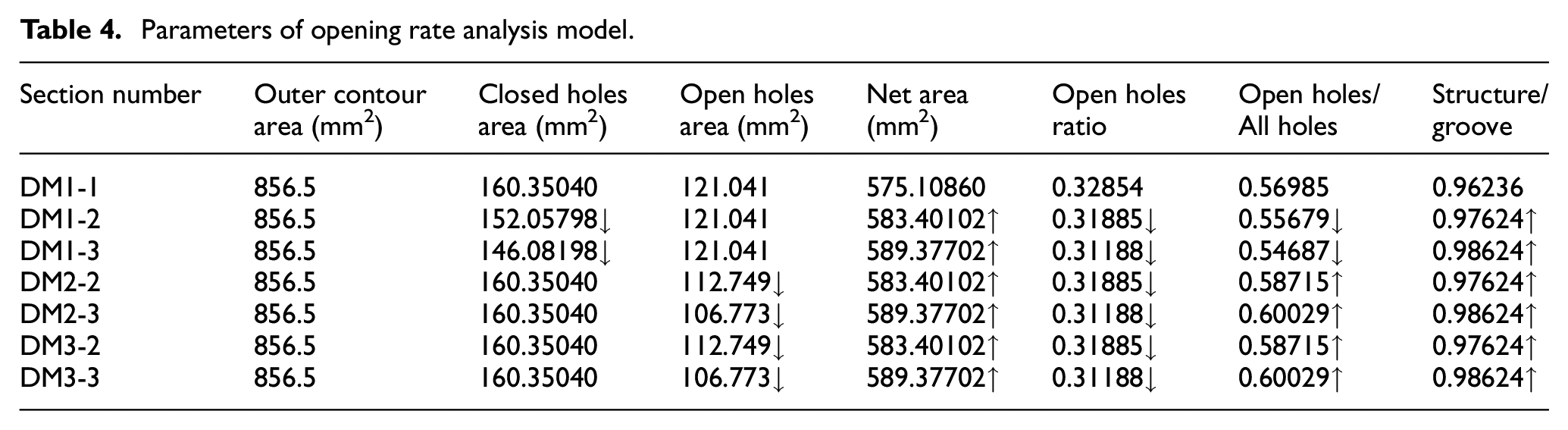
The specific parameters of the gasket model are shown in Table 4, where DM1-1 is the reference section, DM1-2 and DM1-3 are part of the closed holes change, DM2-2 and DM2-3 are part of the circular portion of open holes change, and DM3-2 and DM3-3 are part of the trapeziform portion of open holes change. The gasket thickness H1 is 21 mm and the groove depth is 13 mm, that is, the double-sided model needs to be compressed 16 mm. Completely closed compression analysis was carried out on the seven section models, and the compression force and average contact pressure between the gaskets were obtained. After visualization processing, Figure 10 was obtained. It can be seen from Figure 10 that when the opening rate decreases, the completely closed compression force and the average contact pressure between the gaskets increase with the decrease of the opening rate. When the opening rate decreases by the same value, the distribution characteristics of the completely closed compression force are in order from the large to the small: open holes trapeziform portion > closed holes portion > open holes circular portion. The distribution characteristics of the average contact pressure between the gaskets presents according to the size of order are: open holes trapeziform portion > open holes circular portion > open holes portion. In summary, the completely closed compression force and the average contact pressure between the gaskets are negatively correlated with the opening rate, and have different changing characteristics with the geometry of the portion. When the same change occurs in the opening rate, the change of the trapeziform portion of the open holes has the greatest influence on the completely closed compression force and the average contact pressure between the gaskets. The above research on the opening holes rate of the sealing gaskets provides some references for the improvement of sealing gasket waterproof design. At the same time, from the perspective of the gasket processing quality, testing and evaluation, the holes size must be strictly implemented in accordance with the design size, because the closure compression force and the average contact pressure analysis show that the changes caused by small changes in holes are huge.
Parameters of opening rate analysis model.

Opening rate analysis results: (a) completely closed compression force and (b) average contact pressure between the gaskets.
Impact analysis of rubber hardness
As for the influence of rubber material parameters on sealing gasket design, literature 7 has studied the influence of rubber on the contact pressure distribution trend between gaskets. Literature 14 analyzed the influence of rubber hardness on mechanical properties of sealing gaskets using load deformation curve. Based on the waterproof mechanism, this article analyzes the influence of rubber hardness on gasket waterproof from the perspective of average contact pressure between gaskets.
The analysis model adopts the section of DM1-1 in Table 4. Regarding the hardness of rubber, the hardness range of EPDM porous rubber gasket is specified in the national code for rubber gasket for segment of shield tunnel (GB 18173-2010). 15 Combined with the national code, the analysis range of rubber hardness in this article is 60°–70°. Completely closed compression analysis was performed on the models under the different hardness conditions. The contact pressure distribution between gaskets (the contact surface between the gasket and the gasket) and between gasket and concrete (the contact surface between the gasket and the segment groove) were extracted. After the calculation, visual processing was carried out to obtain Figure 11. It can be seen from Figure 11, when the rubber hardness is within the range of 60°–70°, the average contact pressure between the completely compressed gaskets and the average contact pressure between the concrete and gasket have a linear positive correlation with the rubber hardness. The average contact pressure between the concrete gaskets is higher than the average contact pressure between the rubber gaskets.

Rubber hardness analysis results.
Conclusion
Based on the statistical analysis, the current situation of the sealing gasket design in China studied in this article and the influence of geometric parameters and physical parameters on the waterproof effect of sealing gaskets through numerical simulation are analyzed. The following conclusions are mainly drawn:
At present, the common shield gasket used in China is EPDM “Sheffield” elastic rubber gasket, whose closed holes mostly adopt circular double-row holes structure, for example, the double-row closed holes account for 73.33% of the total, while the sealing gaskets with single-row closed holes only account for 26.67% of the total.
Regression analysis is used to obtain the relationship of the five outer contour parameters of the gasket based on the sealing gasket bottom edge S2. The R value of the determination coefficients of the top edge S1 and the gasket thickness H1 are 0.6985 and 0.7856, respectively, showing a better correlation with the bottom edge S2. However, the R value of determination coefficient after fitting of the shoulder height H2 is only 0.0125, indicating a low correlation between shoulder height H2 and the bottom edge S2. The geometric parameters of seal gasket may be related to the size of the tunnel segment and the waterproof pressure.
The analysis of the number of closed holes rows shows that combined with the average contact pressure retention effect and the machining accuracy angle it is considered that double-row holes are the best waterproof method for closed holes.
The analysis of the closed holes form shows that the descending order of the compression force value of the closed holes is circular aligned holes > semicircular aligned holes > triangular staggered holes > circular staggered holes. The assembly force and the average contact pressure of the arrangement of the aligned holes are higher than the arrangement of the staggered holes, that is, the arrangement of the holes can provide better waterproof effect.
The analysis of the opening rate shows that the completely closed compression force and the average contact pressure between gaskets have a negative correlation with the opening rate. When the same change occurs in the opening rate, the change of trapeziform portion of the open holes has the greatest impact on the completely closed compression force and the average contact pressure between gaskets.
The analysis of rubber hardness shows that, in the range of 60°–70°, the average contact pressure between gaskets and the average contact pressure between concrete and gasket are linearly positively correlated with the rubber hardness.
Footnotes
Handling Editor: James Baldwin
Author’s note
The corresponding author is responsible for submitting a competing interest statement on behalf of all authors of the paper.
Author contributions
Z. J. proposed the original idea for the characteristic parameters optimization based on contact pressure of sealing gasket for segmental joints. C. Y. wrote the main manuscript text and accomplished the numerical simulation. F. Q. prepared all the tables and all the figures. All authors reviewed the manuscript.
Declaration of conflicting interests
The author(s) declared no potential conflicts of interest with respect to the research, authorship, and/or publication of this article.
Funding
The author(s) disclosed receipt of the following financial support for the research, authorship, and/or publication of this article: This paper was supported by the Basic Applied Research Projects of Sichuan Science and Technology Department, No. 2019YJ0349.
Data availability statement
The data used to support the findings of this study are included within the article.