
Abstract
As a kind of promising noncontact bearings, ultrasonic bearings actuated by smart materials such as lead zirconate titanate ceramics show a good application prospect in high-speed machines and precision-measuring devices. The suspending force is one of the most important parameters that play a dominated role on the bearing’s static and dynamic performance. A suspending force model based on acoustic radiation theory for cylindrical object near sound source is built to predict the radial carrying capacity of an ultrasonic bearing actuated by three piezoelectric transducers. To validate the model, an ultrasonic bearing prototype is developed and a testing system is established. For observing the bearing’s dynamic running performance at high speeds, the bearing’s running experiment is carried out and the rotor center’s trajectory data and frequency spectrum are acquired to analyze the bearing’s dynamic characteristics at high speeds. The suspending force model and running performance experiments will contribute to the design, detection, and test of this type of bearings.
Keywords
Introduction
Since conventional contact-type bearings such as deep groove ball bearings and roller bearings usually generate vibration, noise, and overheat when they run at high speeds,1–3 the noncontact-type bearings have a widespread application in industrial fields especially for high-speed occasions due to their small frictional force and high limit speed. Common noncontact-type bearings include hydrostatic bearings, hydrodynamic bearings, and magnetic levitation bearings. 4 For hydrostatic bearings, the use of pumps and the design of pipelines raise the system’s volume and complexity. In addition, the fluid used in the bearing must be clean and dustless.5,6 The hydrodynamic bearings operate based on the principle of hydrodynamic lubrication. The hydrodynamic bearings are more compact than hydrostatic bearings, but in start/stop state or low-speed conditions, the frictional force is large and eccentric problem is inevitable.7,8 In terms of magnetic levitation bearings, an active position feedback system is necessary which makes the control system more complicated.9,10
As a kind of potential smart materials, piezoelectric ceramics have been widely used in the fields of ultrasonic motors,11,12 ultrasonic machining,13,14 and ultrasonic transportation.15,16 The ultrasonic bearing actuated by piezoelectric ceramics is a kind of noncontact-type bearings which is developed based on near-field acoustic levitation effect and piezoelectric driving principle.17,18 Owing to its compact system volume, simpler control, and high limit speed, the ultrasonic bearing shows great potential in high-speed machines and precision-measuring devices. 19 The ultrasonic bearing’s suspending force is one of the vital parameters to the bearing’s static characteristics. The prediction of the suspending force is generally based on nonlinear acoustics or fluid dynamics. Nomura 20 first conducted the research on the acoustic field excited by longitudinal vibration. A gas dynamic equation was established, and MacCormack finite difference scheme was adopted to solve the equation. For a suspension system with specified size and shape, if the longitudinal vibration parameters are given, this model can predict the suspending force generated by longitudinal vibration. Liu 21 and Li 22 studied the acoustic field excited by flexural vibration of a metal disk and investigated the suspending force generated by the flexural vibration. Li et al. 23 also analyzed the gas inertia and boundary effect’s impacts on the suspending force. With regard to this case, Hu et al. 24 carried out a research on the suspending stability and interpreted the generated reason of horizontal restoring force on suspended object. In terms of ultrasonic journal bearings, a majority of suspending theories for rotor are derived from the suspending theories for flat objects. The reason is that if the ultrasonic journal bearing’s vibration surface is spread out in the circumferential direction, the suspension problem to rotors is transformed into the suspension problem to flat objects. The running performance at a high speed is also a vital evaluation index for ultrasonic bearings. The running performance at high speeds can reflect the bearing’s dynamic suspending characteristics. Stolarski and colleagues25–27 established a modified three-dimensional Reynolds equation for an aerodynamic bearing to investigate its suspended rotor’s trajectory changing rule under the perturbation and validate the suspending force’s influence on the bearing’s running stability. For bearings with complex structures such as ball-shaped bearing used in the gyroscope, the finite element software (ANSYS or COMSOL) is generally used to study the ultrasonic bearing’s suspending characteristics. 28 Different from the traditional modeling methods in which the suspension problem on rotors is transformed into the suspension on flat objects, in this article, the suspending force model based on acoustic radiation theory for cylindrical object near sound source is established. According to the solving result of this model, the suspending force’s magnitude and direction are more straightforward. Moreover, the surface topography factor is taken into account to modify the model. In order to verify the model, a prototype is developed and a suspending force testing project is proposed. For the purpose of observing the bearing’s running performance, the rotor center’s trajectory data are extracted and analyzed to investigate the bearing’s dynamic characteristics under radial suspending force when the bearing runs at high speeds. The research on the static and dynamic characteristics based on theoretical and experimental methods will provide a technical support for the development of ultrasonic journal bearings.
Suspending force model for the ultrasonic bearing
Ultrasonic bearing and its gas film structure
The piezoelectric transducers are ideal power sources that are generally adopted in the ultrasonic bearings. In order to realize the stable suspension to the rotor, three or more piezoelectric transducers are used, which are circumferentially equispaced in a housing, with their center lines going through the rotation center of the rotor. In this article, an ultrasonic bearing motivated by three piezoelectric transducers is studied, and the same research method can be generalized to ultrasonic bearings excited by four or more piezoelectric transducers. The structural representation of the ultrasonic bearing actuated by three piezoelectric transducers is shown in Figure 1. The suspension forces generated by the three transducers form the three-point support. Due to the negative correlation between the suspending force and the thickness of the air film, the bearing’s suspending force will automatically keep the rotor at an equilibrium position. When the rotor runs under the suspension of the ultrasonic bearing, the spatial positional relation between the rotor’s center axis and the bearing’s inner ring can be divided into three cases, as shown in Figure 2. In these cases, the shapes of the air film between the bearing and the rotor are different. For case 2: h0 = δ0, the thickness of air film in circumferential direction is uniform. But in case 1: h0 < δ0 or case 3: h0 > δ0, the circumferential thickness of air film is nonuniform. Therefore, the establishment of the suspension force model in the three cases should be taken into account separately. At first, the air film thickness and force deflection angle in the vertical and radial directions at any suspension height h′, φ′, h, and φ are given according to the geometrical relationship, which are listed as follows


The schematic diagram of ultrasonic bearing actuated by three piezoelectric transducers.

Gas film structures in different cases: (a) relative position between the rotor and the radiating surface, (b) gas film in case 1: h0 < δ0, (c) gas film in case 2: h0 = δ0, and (d) gas film in case 3: h0 > δ0.
Modeling of suspending force to a rotor near sound source
If there are two or more different propagation media in an acoustic field, the acoustic radiation pressure will be generated at the interface between two different media. According to the relation between the force applied on the suspended object and increasing rate of acoustic streaming’s momentum, the acoustic radiation pressure can be figured out. For a cylindrical object near a sound source as shown in Figure 3, SE is the bearing’s inner ring surface and SL is the outer circle surface of the rotor. The velocity

where F is the radiation force acting on the rotor,

where k is the wave number, A is the acoustic wave’s vibration amplitude which is the same as the vibration amplitude of the bearing’s inner ring, z is the vibration displacement in the normal direction of the vibration surface, and c is the acoustic wave velocity.
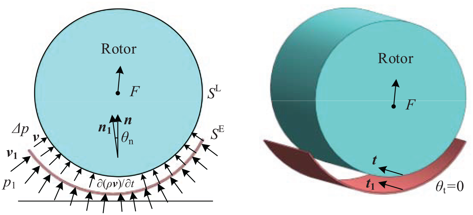
A cylindrical object suspended by a sound field generated by vibration.
According to the acoustic wave equation without external forces, equation (3) can be rewritten as the momentum form shown in equation (5)
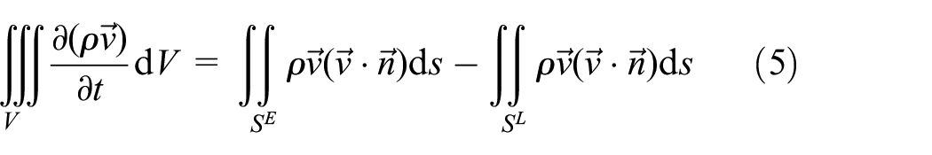
Although the average value of pressure at the interface SL is not zero, the increment of the momentum is zero due to that there is no mass point flow out or in the interface. Thus

According to equations (5) and (6), equation (3) can be changed as
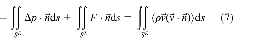
With regard to the acoustic wave, the time-averaged values of sound pressure or velocity at any position in the space are the same. Thus, the selection of the position of SE makes no difference. Now that the radiation force on the area of SL is calculated, we want to put the position of SE close to the area of SL. In this case, the integral domains of the surface integration on both sides in equation (7) are regarded as equal. So, we get

Since the order of the air squeeze film thickness is 10−5 m, which is three orders smaller than the dimension of the vibrating surface (with an order of 10−2 m). Thus, an acoustic wave generated by inner ring of the bearing can be considered an approximate plane wave. When the plane wave lights obliquely to the interface between different propagation media, the phenomena of incidence, reflection, and transmission happen at the same time. If the velocity components of the mass points in all directions for incident wave, reflected wave, and transmitted wave are added up, the expressions of velocity in all directions are acquired. According to equation (8), the radiation force is calculated. Given that the mean energy densities of incident wave, reflected wave, and transmitted wave are presented by Ei, Er, and Et, the radiation forces in normal and tangential directions on the outer circle surface of the rotor Fvz and Fvx are
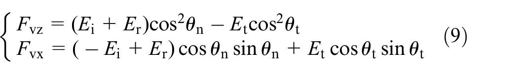
where θn and θt present intersection angles between the direction of the incident wave and normal direction of the rotor’s circle surface and the intersection angle between the direction of the incident wave and tangential direction of the rotor’s circumferential direction, respectively. Since the air film between the rotor and the bearing’s inner ring in the suspension process is consistent along the bearing width direction, the tangential intersection angle θt is zero.
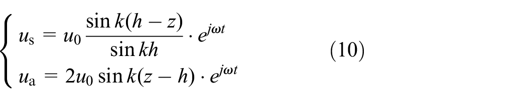
The vibration displacement of the bearing’s inner ring and the particle in the air film us and ua are expressed as
where u0 is the vibration amplitude of the bearing’s inner ring surface. So, the vibration velocity

where v0 is the vibration velocity of the bearing’s inner ring surface. If equation (11) is substituted into equation (8), the acoustic radiation force component ΔFvz and ΔFpz on the area element of the rotor surface ds caused by the particle motion and volumetric change can be derived. If the incident wave is fully absorbed, the radiation force F = Ei. But for fully reflecting surface, the radiation force F = 2Ei. Based on the formula of average acoustic energy density, ΔFvz and ΔFpz are expressed as

Based on the above analysis, the radiation force of the ultrasonic bearing can be calculated by the double integral formula which is as follows
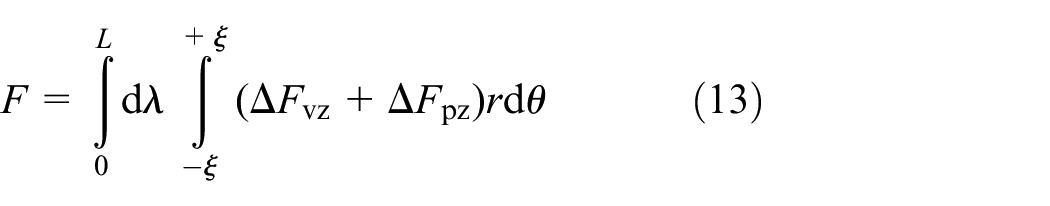
where L is the bearing width and (−ξ, ξ) is the envelop angle scope.
Analysis of surface topography’s impact on suspending force
The model-establishment process is based on the assumption that both the cylindrical surface of the rotor and the inner ring surface of the bearing are ideal smooth surfaces. But actually, these surfaces present the form of long narrow ridges and valleys distributed in the circumferential direction and axial direction which are measured with an atomic force microscope. Under this circumstance, surface roughness will exert a significant impact on levitating force, especially when air film thickness value has the same order as surface roughness value. In order to reasonably describe the topographic characteristics of the rotor and bearing’s surfaces, the surface roughness prediction model σ(δ, μ) based on normal distribution is established. δ is the expected value of surface roughness and μ is the standard deviation of surface roughness. The root-mean-square values of the distance that the rotor and bearing inner ring’s outlines deviate from average lines in sampling length are defined as σr and σR, respectively. Since the surface roughness function is assumed to meet the normal distribution law, random function is introduced into the model to simulate the surface topography. The surface topography of the bearing inner ring and the rotor is shown in Figure 4. If the surface roughness part is substituted into the model, the modified radiuses (rm, Rm) and force deflection angles (φm and


Surface topography sketch of the bearing inner ring and the rotor.
If the above expressions of the modified radiuses (rm and Rm) and force deflection angles (φm and

If both the cylindrical surface of the rotor and the inner ring surface of the bearing are ideal smooth surfaces, the air film thickness and force deflection angle in the vertical and radial direction at any suspension height h′, φ′, h, and φ are used to calculate the radiation force according to equation (13). Due to that these surfaces present the form of long narrow ridges and valleys distributed in the circumferential direction and axial direction, the actual values of previous h′, φ′, h, and φ are modified as
Suspending force testing experiments
Experimental apparatus and method
In order to validate the established suspending force model above, an ultrasonic bearing is developed and a test system is established. For the sake of obtaining a good performance in output characteristics, the PZT-8 ceramics, a kind of emission-type ceramics, are adopted to design and fabricate the piezoelectric transducers. The PZT-8 is a kind of piezoelectric ceramics of PbZrO3-PbTiO3 which have a high mechanical quality factor, a low dielectric loss, and a high Curie temperature. Therefore, the good temperature and time stability on dielectric and elasticity parameters let the PZT-8 ceramics more suitable for power ultrasonic applications. In order to ensure the ultrasonic bearing’s service life, a structure based on the sandwiched-type piezoelectric ceramics is adopted to develop the transducers. A prototype of ultrasonic bearing and the transducer’s basic components are shown in Figure 5. The concave surfaces of the radiation heads of the three transducers form the bearing’s inner ring. The three transducers are mounted in a housing, and each transducer consists of back mass, pre-load bolt, PZT-8 ceramics stack, copper electrode, insulating bush, horn, radiator, and so on.

The prototype of ultrasonic bearing and the transducer’s basic components.
With regard to the ultrasonic bearing, the performance of the piezoelectric transducers is critical which can be reflected from the impedance characteristics. Generally, the impedance characteristics of the transducers can be measured using an impedance analyzer. According to the testing results on Agilent 4395A impedance analyzer, the impedance characteristics of the transducers including the modulus of impedance and phase angle are extracted which are shown in Figure 6. Since the deviation on material parameters, structural dimensions, and assembly technology of the transducers, there is a slight difference in impedance modulus and phase angle between the transducers. Therefore, for the purpose of obtaining consistent output characteristics, each transducer is controlled by an independent controller. When the phase angle of the transducer is not zero, there is a reactive power loss in the transducer. Impedance matching is necessary to eliminate the power loss and improve the acoustic radiation power. Before matching, the parameters of equivalent circuits of piezoelectric transducers including static capacity Cd, dynamic capacity Cm, dynamic resistance Rma, and dynamic inductance Lm should be tested. The measured parameters of equivalent circuits of piezoelectric transducers are shown in Table 1.

Impedance characteristics of the transducers.
Parameters of equivalent circuits of piezoelectric transducers.

The method of series inductance is adopted in impedance matching. The matching inductances of the three transducers are acquired by calculation. Table 2 shows the impedance matching results. The required matching inductances of the transducers are 100.12, 72.72, and 60.60 μH, respectively. After matching, the phase angles of them are all close to zero. Such impedance matching results are acceptable. The experimental testing system is shown in Figure 7. The ultrasonic bearing prototype is installed and fixed on an air floating vibration-isolating platform using two support frames and a few bolts. A rotor with a diameter of 19.94 mm is fabricated. At the both ends of the rotor, cylindrical bosses are designed as measuring surfaces, and two grooves are also designed for hanging the weights. The diameter of the bearing’s inner ring is 20.06 mm. That is, the radius gap size is 60 μm. At the beginning of the experiment, the rotor is placed in the center of the bearing’s inner ring and kept still, and then, the weights with same mass are hanged on the rotor’s end tips of both sides. Two laser displacement sensors with a type of LK-H020 are used to record the rotor’s levitating height in the suspending process. Laser sensor is configured by a controller LK-G5000. Its frequency has nine grades from 1 kHz (1000 μs) to 392 kHz (2.55 μs). In the study, sampling frequency of 392 kHz is chosen to measure levitation heights. Diffuse reflection mode with low requirements to color or surface roughness of the measured piece is adopted in experiments. The repeatable accuracy of the sensor is 0.02 μm, and the precision of the sensors is 1.2 μm. A voltage with amplitude of 150 V is applied to each transducer. When the bearing is powered, the rotor is suspended at a certain height. By changing the weights with different masses hanged on the rotor, the different suspending forces are acquired. To eliminate the effect of external factors, the experiment is conducted in a closed and dustless room.
Working parameters of piezoelectric transducers before/after impedance matching.


The suspending force testing system.
Experimental results
According to the established suspending force model based on acoustic radiation theory in terms of cylindrical object near sound source and taking the surface topography’s effect on suspending process into account, the theoretical result of the bearing’s suspending force can be calculated. The comparison between the theoretical values and the experimental data is given in Figure 8. To validate the repeatability of the experimental results, several experiments at each data point are conducted and a limit range is given. As shown in Figure 8, the red dashed line represents the theoretical result in which the surface topography is taken into consideration. While the black solid line denotes the ideal theoretical model without the surface topography factor, the dash-dotted line means the fitting curve of experimental data’s average values in each point. From Figure 8, it is clearly seen that the suspending force model coincides with the experiment result well if the surface topography factor is taken into account. The surface topography exerts a significant impact on the bearing’s suspending force model when the suspending height is in a range from 15 to 25 μm. This means that the surface topography factor should not be neglected when the value of surface roughness has the same order as the size of the air gap between the rotor and the bearing’s inner ring. As shown in the curve, the suspending force increases with the reduction of the air film thickness in the vertical direction. The bearing can carry a load of 14 N when air film thickness is 15 μm. In the experiments, the amplitude of the vibration on the bearing’s inner ring is about 11 μm. If the vibration amplitude is appropriately raised and the surface quality of the rotor and the bearing’s inner ring is improved, the load-carrying capacity of the bearing will be dramatically improved. During the experiments, some unquantifiable and inevitable influence factors may affect the experimental results. These factors include the gas film oscillation, deviation of transducer’s output characteristics caused by overheat of ceramics, and sensor’s measurement error.

A comparison between the theoretical values and the experimental data.
Dynamic suspending characteristics at high speeds
Measurement system
In addition to the suspending force, the running performance at a high speed is also a vital evaluation index for the ultrasonic bearings. The suspending force represents the bearing’s static suspending characteristic, but the running performance at high speeds can reflect the bearing’s dynamic suspending characteristic.
The research method of the ultrasonic bearing’s running performance at high speeds in this article is based on the analysis of the rotor center’s trajectory data. According to the rotor center’s trajectory data, the eccentricity amplitude curve and the frequency spectrum are plotted, which will contribute to the investigation of the bearing’s dynamic suspending characteristics.
In order to obtain the rotor center’s trajectory data, a measurement system is built as shown in Figure 9. The rotor is driven by a Maxon motor whose rated rotary speed can reach to 64900 r/min. The motor connects to the rotor by a flexible coupling at one end of the rotor. At the other end of the rotor, a boss is designed that is used as measuring surface. Two laser displacement sensors are installed in the horizontal and vertical directions, respectively. When the rotor operates at a high speed, the two sensors can record the rotor center’s trajectory.
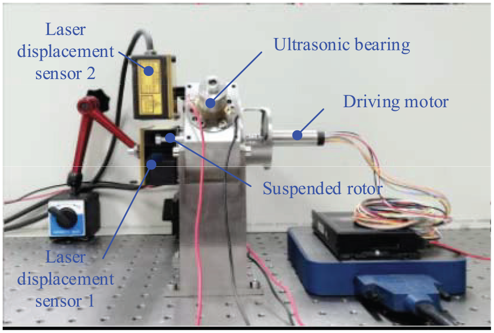
The measurement system of rotor center’s trajectory data.
Analysis on dynamic suspending performance
In the experiment, the motor is actuated by ramp speed signal, and the rotor runs from 0 to 20,000 r/min at a constant acceleration within 8 s. The rotor center’s trajectory characteristics are extracted. The trajectory signals are captured when the rotary speeds are around 18,474, 19,062, and 19650 r/min, respectively, as shown in Figure 10. From time 13.00 to 13.15 s, when the rotor operates around 18,474 r/min, it is clearly seen from Figure 10(a) that the motion of the rotor is a kind of periodic motion. The maximum eccentric amplitude of the rotor is about 22.74 μm. With the increase in the rotary speed, the rotor’s motion begin to transform to the quasi-periodic motion from periodic motion caused by eccentric loads and external disturbances. As shown in Figure 10(b), when the rotor runs at speed of 19,062 r/min, the rotor center’s motion appears to be quasi-periodic oscillation. At this moment, the maximum eccentric amplitude of the rotor reaches to 27.73 μm. When the rotary speed reaches to 19,650 r/min, the rotor center’s trajectory is superposition of two periodic motions shown in Figure 10(c). If the rotary speed of the rotor raises continuously in this case, the rotor will operate in multiply periodic motion state until the rotary speed exceeds the limit speed.

The trajectory signals and the frequency spectrums at speeds of around (a) 18474 r/min, (b) 19062 r/min, and (c) 19650 r/min.
According to above experimental results, it is found that the low-frequency vibration energy will constantly accumulate with the increasing of rotary speed, which induces the running state’s transformation of the rotor from periodic motion to quasi-periodic motion or multiply periodic motion. Due to the limit of levitating load-carrying capacity, the eccentric loads caused by dynamic unbalance will exceed the bearing’s suspending force. In this case, the contact and rub-impact between the rotor and the bearing will occur if the rotary speed increases continuously. Actually, the eccentric loads are derived from the following factors: (1) inconsistency of the three piezoelectric transducers’ output characteristics, (2) dynamic unbalance caused by the rotor’s form error and asymmetric distribution of mass, (3) coaxiality between the rotor and the motor shaft, and (4) gas membrane oscillation caused by surface roughness and gas compressibility. Many factors above are uncontrollable or inevitable, but the vibration parameters of the bearing inner ring can be appropriately designed according to the suspending force model to increase the bearing load-carrying capacity and correspondingly improve the rotary speed limit. If we want to enhance the bearing’s running stability at high speeds, increasing the suspending force is a significant and effective method in addition to the improvement of the bearing’s manufacturing and assembly accuracy.
Conclusion
Since cylindrical rotor of the ultrasonic bearing has more complicated boundary condition and reflected wave than the plat object, the sound field excited by the transducers between the bearing and the rotor always can be approximated by regional plane wave and the radiation force is calculated by surface integral eventually. Based on the above idea, the suspending force model taking the surface topography into account for cylindrical object near sound source is established. The suspending force testing experiment illustrates that the model can accurately predict the bearing’s radial carrying capacity. The deviation between the theoretical and experimental results is within the range of error permitting. The bearing’s running performance experiments at high speeds are also conducted. The frequency spectrums and the trajectory plots reveal the rotor motion state’s transformation process from periodic motion state to multiply periodic motion state. The experiments also find the speed at which the rotor’s running state transforms from periodic motion state to two-periodic-motion state is about 19,062 r/min. Since the eccentric amplitude rises with the increasing of the rotary speed, the bearing should run at a speed that less than its limit speed. To raise the bearing’s limit speed under stable operating condition, the improvement of suspending force is an effective and remarkable way.
Footnotes
Appendix
Handling Editor: James Baldwin
Declaration of conflicting interests
The author(s) declared no potential conflicts of interest with respect to the research, authorship, and/or publication of this article.
Funding
The author(s) disclosed receipt of the following financial support for the research, authorship, and/or publication of this article: This project is supported by National Natural Science Foundation of China (Grant No. 51905314), Natural Science Foundation of Shandong Province under grant nos ZR2019BEE017 and ZR2018BEE014, and Key Research and Development Project of Shandong Province (no. 2018GGX103027).