
Abstract
Sediments frequently appear at the bottom of oil and gas wells in the bottom of carbonate rocks during completion or production, seriously affecting the productivity. In order to solve the wellbore cleaning problem, this article applies the Bernoulli equation theory method, the finite element method based on the standard turbulence model and the laboratory test to verify a kind of negative pressure wellbore cleaning tool which can establish local reverse circulation under the action of high-pressure water jet and salvage the bottom debris. Through the numerical analysis of the cleaning tool structure, it is found that the wall face diameter is at least two times of the nozzle hole diameter to effectively play the cleaning tool performance. If the total area of nozzle outlet is 48π mm2, the cleaning tool fishing capacity of six nozzle structures is improved the most. The analysis of the adaptability of the cleaning tool shows that the cleaning tool with an outer diameter of 104 mm is most suitable for the casing shaft with an inner diameter of 127.3 mm. The cleaning tool was applied to the field operation and successfully cleaned the wellbore, effectively increasing the wellbore productivity.
Keywords
Introduction
In recent years, conventional oil and gas resources have been continuously exhausted, and the exploitation of unconventional natural gas, such as shale gas, has been developed rapidly worldwide. However, in the process of shale gas exploitation, sediments may appear at the bottom of the well, which will not only affect the downflow of subsequent tools, but also block the production layer during the production process, leading to the production capacity decline and even stop production. 1
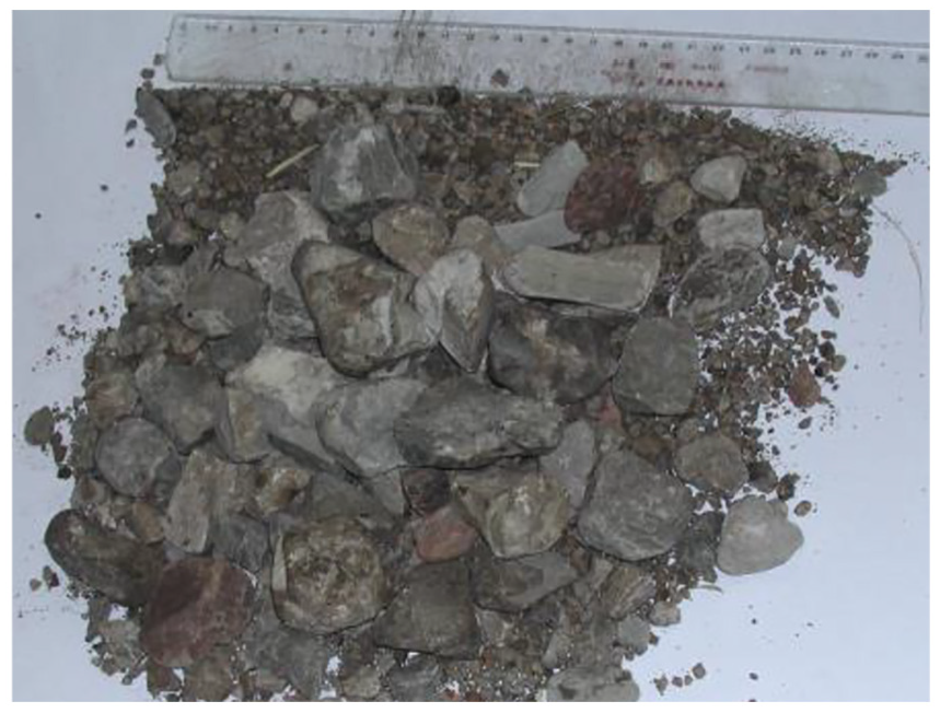
There are two main reasons for the deposition of shale gas wells. First, the reservoir formation of shale gas is mainly characterized by adsorption state or free state, and horizontal well casing completion and segmented fracturing and acidification technology are often used in the exploitation. 2 Fracturing and acidification change the stress of the reservoir rock, causing the shaft wall to fall or even collapse, as shown in Figure 1. Second, debris, frac sand, and what kind of iron chips and other impurities are deposited at the bottom of the well after grinding from the bridge plug used for fracturing, as shown in Figure 2.
Disjointed shaft wall.

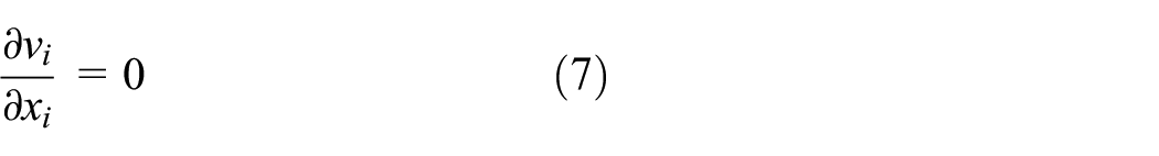
Impurities deposited at the bottom of the well.
In order to increase oil and gas production capacity, impurities must be cleaned up after a certain depth of deposit at the bottom of the well. Even if these residues are continuously deposited in the wellbore, risks such as high torque, high resistance, and stuck drilling may occur during the operation.3,4 The existing cleaning technology can be divided into continuous pipe flushing and sand washing and blowout reverse drainage. Coiled tubing flushing is the process of pumping out bottom hole debris using positive circulation by running coiled tubing.5–7 In the process of discharging the fracturing fluid to the ground, all kinds of impurities in the well are driven to discharge to the ground. However, both of these technologies have some common shortcomings, such as when the sediment particles at the bottom of the well are large, they cannot be carried out of the wellhead. After the high-pressure pump stops, the impurities may fall back to the bottom of the well again, causing stuck.8,9 In addition, if the reservoir is carbonate fissure and cave formation, not only the shaft wall is prone to collapse, but also the bottom of the well is prone to serious leakage, unable to establish circulation. As a result, sand washing and blowout preventer flowback technology are difficult to meet the needs of unconventional gas such as shale gas bottom cleaning.
In order to solve the problem of poor cleaning effect of bottom hole impurities in oil and gas wells, a cleaning tool based on negative pressure suction operation was proposed in recent years. The bottom hole cleaning tool uses the negative pressure effect of jet to generate negative pressure internally, and draws a string of straws to clean the impurities at the bottom hole.10,11 The basic principle is shown in Figure 3. The key to this new bottom hole cleaning tool is the design of the negative pressure generator and how to use limited wellbore space to produce the best negative pressure suction effect.

Schematic diagram of cleaning tool salvage.
Negative pressure effect has been extensively studied in other industries, such as Thomas et al., 12 Jeon and Jung, 13 Tsai and Tsai, 14 Bi et al., 15 and Andersen et al. 16 applied it to the pulse jet precipitator and found that the negative pressure pipe can significantly improve the cleaning efficiency. Paterson, 17 Eckerle, 18 and Sundararaj and Selladurai 19 used the principle of negative pressure of jet to mix two kinds of liquids to study the effects of different injection angles and different jet momentum on the concentration of the two mixtures. Boersma et al. 20 predicted the intensity, pressure, and mixing concentration of turbulence in the jet stream. Krothapalli et al., 21 Raman and Taghavi, 22 Smith and Mungal, 23 Demuren, 24 Sherif and Pletcher, 25 and Said et al. 26 divided the jet process into three stages: the unmixed region, the mixing region, and the mixing stable region, so as to better describe the suction roll phenomenon of negative pressure effect. However, the application of negative pressure effect to bottom hole cleaning tools is rarely studied, and the process of dredging impurities by negative pressure wellbore cleaning tools is not well understood.
Therefore, this article first analyzed the mechanism of negative pressure wellbore cleaning tool through theoretical method, numerical simulation, and laboratory test, and verified the feasibility of negative pressure wellbore cleaning tool. Second, the numerical model is used to optimize the structure of the negative pressure generator to improve the fishing ability of cleaning tools, and the adaptability of cleaning tools is analyzed to obtain the wellbore suitable for cleaning tools. Finally, the successful cases of the field application of negative pressure wellbore cleaning tools are given.
Mechanism analysis of negative pressure wellbore cleaning tool
Theoretical mechanism analysis
Since the working fluid used in the negative pressure wellbore cleaning tool can be regarded as incompressible fluid, Bernoulli equation is used to obtain27,28
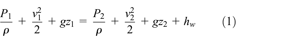
in which P1 and P2 are the fluid pressure before and after the nozzle; v1 and v2 are the fluid velocity before and after the nozzle;
According to the same discharge before and after the short node of the nozzle, we can get

in which Q is the displacement of the over current surface, n is the number of nozzles for the negative pressure wellbore cleaning tool.
The variation of gravitational potential energy can be ignored because of the shorter jet stub. Substituting equation (2) into equation (1) to obtain nozzle outlet pressure as follows
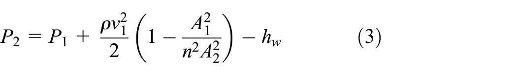
The nozzle structure of the negative pressure wellbore cleaning tool is shown in Figure 4. The inlet area A1 is greater than the outlet area nA2. Therefore, according to equation (3), the outlet pressure P2 will be less than the inlet pressure P1, and significant pressure drop will occur after the jet flows through the nozzle. Therefore, the high-pressure water jet forms a negative pressure zone near the impact nozzle and absorbs the fluid under the negative pressure generator.

Negative pressure wellbore cleaning tool nozzle.
In addition, the high-pressure water jet from the impact nozzle also has a coiling effect on the surrounding fluid. The simplified theoretical model is used to explain the entrained jet

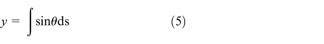
Equations (4) and (5) give the coordinate transformation between the coordinates (x, y) and (s,
The local coiling velocity was obtained by Hewett et al. 29

in which
Finite element mechanism analysis
Numerical method
The standard model
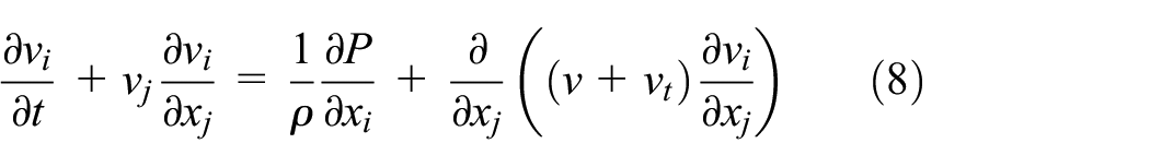
in which v is kinematic viscosity, vt is the eddy current viscosity, vt is the average velocity in the direction xi, and p is real-time pressure.
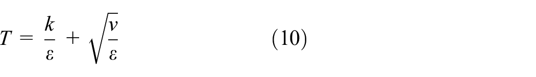
Turbulent time scalar T and viscosity vt can be expressed as

The flow interruption coefficients k and ε in the standard k–ε model can be obtained through the transport equation


in which
In the model of turbulent mass transfer, the tracer conservation equation is

in which c is average concentration,
As shown in Figure 5, a venturi-based wellbore cleaning tool model was established, which mainly included injection nipple, suction nipple, filter nipple, shunt nipple, one-way valve nipple, debris collection cylinder, bottom hole, and casing. The whole model has a total length of 4200 mm and a diameter of 25 mm.

Cleaning tool model.
Calculation results and discussion
Figure 6 shows the negative pressure wellbore cleaning tool nozzle outlet and its adjacent fluid vector velocity. During the cleaning tool operation, the fluid is ejected from the cleaning tool nozzle to form a high-speed water jet. The high-speed water jet generates tangential coiling effect on the surrounding fluid. The surrounding fluid then forms a vortex under the tangential force and is sucked by the high-speed water jet, which flows out of the cleaning tool wall face together. The sucked fluid near the nozzle outlet is replaced by the lower fluid, which circulates in turn, eventually forming a reverse circulation system inside the tool and within the annulus.
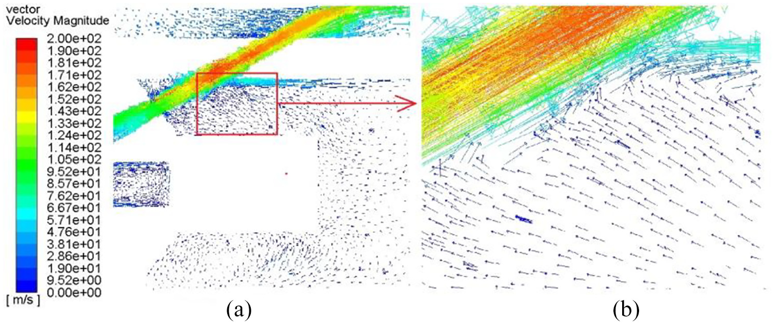
Vector velocity diagram of cleaning tool nozzle outlet: (a) global diagram; (b) local diagram of nozzle outlet.
Figure 7 shows the pressure cloud diagram during the jet process of the cleaning tool nozzle in the negative pressure wellbore. Obviously, the pressure at position a near the nozzle is significantly lower than at other positions in the tube. This indicates that the flow surface of the jet decreases obviously after flowing into the nozzle, and the jet drops at the nozzle outlet, resulting in a low-pressure area near the nozzle. Therefore, significant pressure gradients are formed for the fluid in the cleaning tool tube, as shown in Figure 7 at points A, B, C, and D. Under the action of the pressure gradient, the fluid in the tube is sucked into the vicinity of the nozzle and then mixed with the high-pressure water jet and shot out from the wall outlet. When the mixed fluid passes through the wall outlet, the passing surface decreases again and the static pressure decreases again. At this point, the pressure inside the negative pressure wellbore cleaning tool is significantly higher than the outlet pressure, so the fluid inside the tool will flow into the wellbore annulus under the action of pressure gradient and high-speed jet.

Static pressure diagram of negative pressure wellbore cleaning tool.
Therefore, the negative pressure wellbore cleaning tool under the negative pressure and suction of the high-pressure water jet forms a local reverse circulation at the position of the cleaning tool at the bottom of the wellbore. The cuttings at the bottom are brought into the tool under the action of the fluid, and are left in the debris collection cylinder under the action of the screen, thus completing the bottom hole debris cleaning.
Experimental verification
In order to verify the feasibility of cleaning tools, the non-submergence test was carried out on the jet sub of negative pressure wellbore cleaning tools. As shown in Figure 8(a), first, the jet sub is fixed on the four-dimensional water jet test table, and the wellbore cleaning tool is connected to the high-pressure pump by high-pressure rubber hose. After injecting the high-pressure fluid into the jet short joint, it was found that all the high-pressure water jets flowed out of the nozzle exit, as shown in Figure 8(b). It indicates that the design of jet sub is reasonable and the air pressure zone is formed in the jet sub.
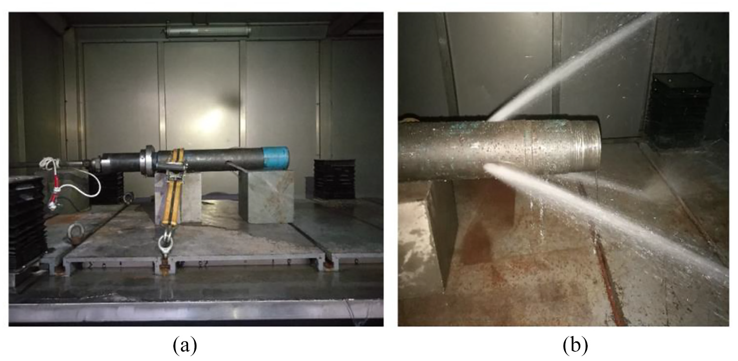
Jet sub test validation: (a) tool installation and (b) test process.
Second, the negative pressure wellbore cleaning tools were tested for debris salvage, and the test bench as shown in Figure 9(a) was built. The negative pressure wellbore cleaning tool was connected to the high-pressure pump by high-pressure rubber hose, and 1 kg of debris particles were put into the bottom of the simulated wellbore. After starting the high-pressure pump, slowly boost the pressure and observe the abrasive status in the wellbore. The test process is shown in Figure 9(b). The abrasive first obtains the initial velocity under the action of high-pressure water jet, then the negative pressure wellbore cleaning tool establishes the reverse circulation and the debris particles begin to migrate upward, and finally all the debris is retrieved.

Negative pressure wellbore cleaning tool salvage test: (a) test bench; (b) test process.
Therefore, the feasibility of negative pressure wellbore cleaning tool is verified by theoretical method, finite element method, and experimental method. Through the negative pressure generated by the high-pressure water jet and the suction effect of the high-speed water jet, local reverse circulation was established in the cleaning tools and sections of the negative pressure wellbore to salvage the bottom debris.
Cleaning tool spray sub structure optimization
In order to make the negative pressure wellbore cleaning tool under the same operating parameters to achieve the best fishing effect, first of all, the structure of the negative pressure wellbore cleaning tool should be optimized to minimize the energy loss caused by the injection stub. Therefore, the nozzle structure should be optimized to obtain the best fishing performance under the same working parameters.
Tool wall hole and nozzle diameter ratio
According to the characteristics of high-pressure water jet, the movement of the fluid after flowing through the nozzle will have diffusivity. As the only outlet of the cleaning tool fluid in the negative pressure wellbore, the wall hole is directly related to the cleaning effect of the tool. Therefore, the wall opening and nozzle diameter ratio of negative pressure wellbore cleaning tool were analyzed to obtain the best diameter ratio. As shown in Table 1, different wall opening and nozzle size and diameter ratio schemes are given.
Size and diameter ratio of different wall orifices and nozzle orifices.

Figure 10 shows the pressure difference between nozzle outlet and nozzle outlet at 250, 1000, 2000, 3000, 4000 mm, and bottom hole location, respectively. When the diameter of the nozzle is 6 mm and the diameter of the wall hole is equal to the diameter of the nozzle, the farther the position of the tube is from the position of the nozzle, the more positive the pressure difference tends to be, as shown in Figure 10(a). This indicates that the wall opening and nozzle size design in case 1 cannot form the pressure distribution with small pressure in the upper part of the pipe and large pressure in the bottom hole, and the reverse circulation of fluid in the cleaning tool section cannot be formed. As shown in Figure 11(a), a vortex is formed in the suction stub position chamber and the fluid turns. Figure 11(c) also shows the downward movement of fluid inside the tool, which in turn flows into the bottom hole. Noting that part of the jet fluid is discharged from the nozzle into the tube, rather than taking the fluid out of the tool. The fluid emitted through the wall face of the cleaning tool flows downward through the thickness of the impact casing wall, but because the bottom hole fluid flows upward through the casing annulus, the jet fluid also deflected at Figure 11(b). Therefore, the flow direction of the whole fluid in the cleaning tool section is positive circulation, and the design parameters of case 1 cannot achieve the function of cleaning the debris at the bottom of the well.

Static pressure difference between different positions in the pipe and nozzle outlet positions—(a) nozzle diameter: 6 mm; (b) nozzle diameter: 8 mm; (c) nozzle diameter: 10 mm.

Flow field diagram of nozzle position in case 1: (a) global diagram, (b) local diagram of annulus and (c)local diagram of suction inlet.
In case 2, the wall hole diameter is 1.5 times the nozzle diameter. Although the pressure at a distance of 1000 mm from the nozzle mouth is less than that at the nozzle mouth, under the action of high-speed jet winding, reverse circulation is still formed in the tool section, but the winding ability is poor and the best fishing effect cannot be achieved. In case 3 and case 4, obvious pressure gradients can be found. The farther away from the nozzle, the greater the pressure difference. It indicates that these two schemes can meet the design requirements, and the pressure difference of case 4 is the most obvious. It indicates that when the diameter of the nozzle is 6 mm and the diameter of the wall hole is 2.5 times of the diameter of the nozzle, it is more conducive to constitute the reverse circulation of the bottom hole, and the bottom hole cleaning effect is the best.
As shown in Figure 10(b) and (c), the pressure gradient in the cleaning tool tube is the most obvious when the nozzle orifice diameter is 8 and 10 mm and the wall face diameter is two times of the nozzle diameter. When the diameter of the wall face is the same as the diameter of the nozzle, that is, in case 5 and case 9, no significant pressure drop can be formed inside the cleaning tool, which cannot meet the design requirements. So, the wall face diameter must be larger than the nozzle diameter. But, not the wall face hole is bigger the better. In Figure 10(b) and (c), the pressure gradient effect when the wall face diameter is 2.5 times of the nozzle diameter is significantly lower than that when the nozzle diameter is 2 times. Taking the nozzle diameter of 8 mm as an example, Figure 12 shows the vector velocity near the nozzle in case 7 and case 8. In case 7, compared with case 8, the velocity at the exit of the nozzle and at the position of the wall face is larger, so the suction effect of the high-pressure water jet on the fluid inside the pipe is greater. The reason may be that when the wall face is too large relative to the nozzle diameter, the high-pressure water jet is given too much diffusion space. Meanwhile, the tangential resistance of the fluid in the pipe received by the high-pressure water jet is also greater, resulting in the rapid decline of the velocity of the high-pressure water jet and the reduction of the suction capacity.

Case 7 and case 8 vector velocities near nozzles.
By analyzing the size of nozzles and wall faces of different negative pressure wellbore cleaning tools, it is found that no matter what the diameter of the nozzle is, as long as the diameter of the wall face does not exceed the diameter of the nozzle, the injection nipple cannot form a reverse circulation at the bottom of the well, let along the effect of cleaning the bottom of the well. When the nozzle mouth is 6 mm, compared with the large-diameter nozzle, when the pump pressure and displacement are the same, the jet velocity and momentum obtained by the large-diameter nozzle are larger, and the wall face diameter is 2.5 times of the nozzle diameter, which is more conducive to bottom hole impurity cleaning. However, when the nozzle diameter is 8 and 10 mm, the jet velocity and momentum at the nozzle outlet decrease. If the wall face is too large, the tangential resistance of the high-pressure water jet is greater, resulting in a weakened ability of the high-pressure water jet to suck the nearby fluid. If the wall face is too small, it cannot provide unobstructed channel for the high-pressure water jet and the fluid inside the pipe, preventing the fluid from flowing out of the pipe and establishing reverse circulation. Therefore, the diameter of the wall face is twice the diameter of the nozzle, which is more conducive to bottom hole impurity cleaning.
Number of nozzles
The number of nozzles is an important parameter in the design of negative pressure wellbore cleaning tool. When the nozzle diameter is the same, increasing or decreasing the number of nozzles will not only change the suction orifice, but also change the total area of nozzle outlet, resulting in changes in the velocity and momentum of jet fluid. Therefore, the number of nozzles directly affects the cleaning effect of the negative pressure wellbore cleaning tool. Table 2 shows four cases where the number of nozzles is 3, 4, 6, and 8, respectively, when the nozzle diameter is 8 mm and the wall face diameter is 16 mm.
Same nozzle diameter, different nozzle number.

Figure 13 shows the influence of different nozzles on cleaning tools. Figure 13(a) shows the difference between nozzle outlet pressure and in-tube nozzle outlet pressure of 250, 1000, 2000, 3000, 4000 mm, and bottom hole pressure. In all cases, the pressure inside the tube decreases from top to bottom with the distance from the nozzle increasing, forming an obvious pressure gradient. This indicates that all cases can form negative pressure at the position of the nozzle, and produce suction effect on the bottom hole medium, and form local reverse circulation at the bottom hole tool section. In addition, when the pump pressure and displacement are the same, the pressure gradient gradually decreases with the increase in the number of nozzles.

Influence of number of nozzles on cleaning tool: (a) static pressure; (b) speed.
Figure 13(b) shows the average fluid velocity from the nozzle outlet 250, 1000, 2000, 3000, 4000 mm, and bottom hole locations. The same as the result of pressure, the flow velocity decreases with the increase in the number of nozzles. The bottom hole flow rate is the largest in case 7, indicating that the number of nozzles is 3, and the disturbance to the bottom hole debris is the largest, which is the most conducive to obtaining the initial velocity of cuttings and entering the cleaning tool with the fluid. Cleaning tool design diameter is 25 mm, so the fluid and cuttings into the tube after the speed is significantly increased.
Therefore, when the diameter of the nozzle is the same, the number of nozzles will increase the jet channel and the fluid suction inlet of the tube, but the total area of the nozzle outlet will also increase, resulting in a significant decrease in the pressure drop and velocity of the nozzle outlet. Therefore, increasing the nozzle outlet area will reduce the cleaning performance of the cleaning tool. In order to exclude the influence of the total area of nozzle outlet on the cleaning tool performance, Table 3 shows the cases where the total area of nozzle outlet remains the same with different nozzle diameters and number of nozzles. The wall face diameter is set to twice the nozzle diameter.
The total area of the same outlet and the number of different nozzles.
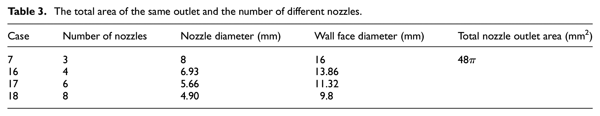
Figure 14 shows the pressure cloud diagram near the nozzle when the total area, inlet velocity, and inlet pressure are the same, and the number and diameter of nozzles change. An obvious commonality is that the pressure near the nozzle outlet is lower than the pressure at other locations, indicating that all case designs can generate differential pressure inside the negative pressure wellbore cleaning tool, forming a reverse circulation system. Through data analysis, the pressure difference between nozzles and bottom of the well in case 7, case 16, case 18, and case 19 was −3.08, −3.46, −3.68, and −3.56, respectively. The pressure difference first increases with the number of nozzles and then decreases, among which the pressure difference reaches its maximum when the number of nozzles is 6. Figure 14 also shows that the pressure value near the nozzle in case 17 is the smallest. It indicates that when the number of nozzles is 6, it is most conducive to the generation of negative pressure of cleaning tools and the cleaning ability is also the strongest.

Influence of number of nozzles on pressure near nozzles.
Although the high-pressure water jet from the nozzle after the injection of the nearby fluid suction effect, but the high-pressure water jet on the surrounding fluid suction range is limited. In order to fully understand the influence of the number of nozzles on the cleaning tool performance. Figure 15 shows the fluid vector velocity at the nozzle outlet section. As the number of nozzles increases, the flow velocity at the nozzle outlet decreases. However, it can be known from the properties of incompressible fluid that when the total area of nozzle outlet is the same, the inlet condition is the same and the outlet velocity is the same. This indicates that the number of nozzles increases, the momentum of the fluid at a single outlet decreases, and the velocity decreases rapidly when mixing with the fluid inside the tool. In addition, the increase in the number of nozzles may also increase the loss of high-pressure water jet energy, resulting in the reduction of velocity. Although the increase in the number of nozzles reduces the flow rate at the nozzle outlet, the number of nozzles is more favorable to the formation of reverse circulation than the number of nozzles is 4. By analyzing the fluid vector velocity given in Figure 15, it can be seen that each high-pressure water jet affects only a limited amount of nearby fluids. The number of nozzles is small. For example, in case 7, the fluid in the middle of the two nozzles has a small tangential force under the high-pressure water jet, so the obtained velocity is also small. However, when there are too many nozzles, such as case 18, the fluid between the two nozzles is affected by two high-pressure water jets at the same time, resulting in the waste of capacity. Therefore, only when the number of nozzles is appropriate, the high-pressure water jet can achieve the best capacity utilization and improve the fishing ability of cleaning tools.

Influence of number of nozzles on nearby flow field.
The nozzle angle
Different nozzle design will not only affect the flow momentum at nozzle outlet, but also affect the loss of fluid energy. If the nozzle structure design is not reasonable, it will lead to a lot of high-pressure water jet capacity loss, reducing the performance of negative pressure wellbore cleaning tools. The nozzle angle is an important parameter of nozzle structure design, which directly affects the cleaning tool performance. Therefore, Table 4 gives different nozzle angles to determine the optimal nozzle structure design. In order to reduce the impact of water jet on the wall of the tool, the opening angle of the wall is set to be the same as that of the nozzle.
Cases of different nozzle angles.

The smaller the angle between the nozzle and the cleaning tool axis, the smaller the steering angle of the high-pressure water jet entering the nozzle, and the smaller the energy consumption of the nozzle. Figure 16 shows the vector velocity of the nozzle and its vicinity at different nozzle angles. Obviously, the velocity vectors in the four cases are basically the same, but in case 19, the included angle between the nozzle and the cleaning tool axis is the smallest, and the component of the nozzle shooting from the wall face into the inner wall of the casing is the smallest. With the increase in nozzle angle, the radial component of high-pressure water jet impinging on the casing increases and the energy loss also increases.

Influence of nozzle angle on jet flow.
Case 19–case 22 static pressures near the nozzle orifice are 8.11, 8.14, 8.29, and 8.14 MPa, respectively, indicating that the nozzle angle of 20° is most conducive to the formation of reverse circulation system for cleaning tools. An interesting phenomenon is that when the nozzle angle increases from 30° to 35°, the static pressure around the nozzle decreases again, indicating that an appropriate increase in the injection angle after 30° is beneficial to the generation of negative pressure. This is because the flow direction of the fluid in the tube is from the bottom up, while the axial direction of the high-pressure water jet is found from the bottom up. So, the cleaning tool operation in the suction sub-produced significant vortex, the tendency of the fluid in the tube to turn. The smaller the injection angle of the nozzle, the larger the required steering angle near the nozzle and the higher the energy consumption of the high-pressure water jet. So, the cleaning tool injection angle is too small and it is not conducive to the formation of the bottom hole reverse circulation.
Cleaning tool wellbore adaptability analysis
Wellbore size adaptability
The outside diameter of the cleaning tool designed in this article is 104 mm, but the cleaning operation may occur in any well type and section. The same cleaning tool may only be used for a limited range of wellbore sizes, so an analysis of the cleaning tool’s suitability is required to determine the range of use of the tool. Table 5 shows the casing with five different specifications, and analyzes the influence of clearance size between the outer diameter of cleaning tool and the inner diameter of casing on the bottom hole cleaning effect.
Cases of different wellbore specifications.

Figure 17 shows the influence of different annulus clearance on nozzle location and bottom hole static pressure. The larger the annulus gap, the larger the channel provided for the fluid, making the fluid flow in the annulus smoother. However, when the annulus clearance is too small, such as case 23, the pressure is too high either at the bottom of the well or near the nozzle. This is because when the annulus clearance is too small, causing the annulus and cleaning tools internal fluid flow blocked, the phenomenon of holding pressure. When the annulus clearance is greater than 11.65 mm, the pressure change trend of nozzle and bottom hole decreases. Figure 17(b) also shows that the annulus clearance is approximately 11.65 mm and the negative pressure at the nozzle and bottom hole reaches the maximum of −3.08 MPa. From the perspective of static differential pressure, the 104-mm outside diameter cleaning tool is most suitable for wells with 5 1/2 in casing and 127.3-mm inside diameter.
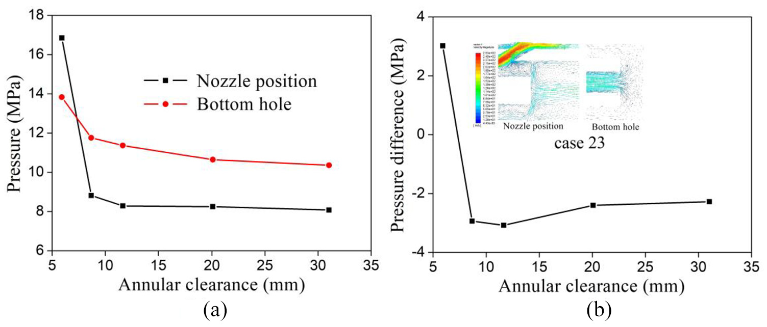
Influence of annulus clearance on static pressure: (a) nozzle and bottom hole pressure; (b) pressure difference between nozzle and bottom hole.
When the annulus clearance is 5.91 mm, the pressure near the nozzle is 3.02 MPa higher than the bottom hole pressure, and no negative pressure gradient is formed in the cleaning tool wellbore. According to the velocity vector diagram near the nozzle and at the bottom of the well given in case 23 in Figure 17(b), it is found that in case 23, although the bottom of the well pressure is greater than the internal pressure of the cleaning tool, the reverse circulation is still established in the cleaning tool section. It shows that the establishment of reverse circulation of cleaning tool depends not only on the pressure gradient but also on the entrainment of high-pressure water jet.
Annulus clearance not only has great influence on the pressure of cleaning tool section, but also has great influence on the flow rate. When the inlet pressure and displacement are the same, the smaller the annulus clearance is, the faster the flow velocity is in the cleaning tool, as shown in Figure 18. Therefore, the smaller the annulus clearance, the more conducive to improve the efficiency of cleaning tools. However, although the flow rate of case 23 is higher than that of other cases, it cannot produce effective negative pressure, which makes the salvage capacity limited. And annulus clearance is too small, easy to cause tool stuck, or unable to enter. Therefore, combined with pressure and velocity, the 11.65-mm annulus clearance is most suitable for fishing tools with an outer diameter of 104 mm.

Influence of annulus clearance on internal velocity of cleaning tool.
Field application
The completion depth of the fault well was 4100 mm. Maximum inclination is 105.1°. The casing parameters are 139.7 mm, and the inner diameter is 114.3 mm. The pump pressure is 19–25 MPa, and the displacement is 300–480 L/min. During the logging operation, the hole was blocked at 2180 m. Through the previous operation and flowback analysis, it was determined that the wellbore was blocked due to bridge plug failure.
After the plug is broken, large pieces of plug debris appear in the wellbore, which are difficult to carry out by positive circulation. Therefore, the negative pressure wellbore cleaning tools are used for fishing operations. In order to improve operation efficiency, the tool assembly is slope drill pipe + negative pressure wellbore cleaning tool + long barrel + wire dredge. Figure 19(a) is the field operation process. After several fishing operations, the bridge plug debris as shown in Figure 19(b) was obtained and the well blockage problem was successfully solved. Therefore, the negative pressure wellbore cleaning tool plays a crucial role in the workover process. Once again, it proved that the negative pressure wellbore cleaning tool can effectively solve the problem of the inability to establish circulation and the need to clean rubber, debris, or debris in the well.

Field application of cleaning tools: (a) field operation; (b) salvage of debris.
Conclusion
In order to solve the problem that the debris at the bottom of the well cannot be solved by normal operation such as positive circulation and blowout prevention and reverse drainage, this article puts forward a kind of negative pressure tool for cleaning the bottom of the well. To verify the effectiveness and rationality of the design tool, the following conclusions are obtained through analysis:
The theoretical method of Bernoulli equation, standard finite element method based on fluent, and laboratory test were used to verify that the cleaning tool could establish local reverse circulation under the action of high-pressure water jet to clean the bottom of the well.
When the pump pressure and displacement are the same, a nozzle with a diameter of 6 mm corresponds to a wall face size 2.5 times the nozzle diameter, which is the best. The wall face size of 8 and 10 mm nozzles corresponding to two nozzle diameters is optimal. The smaller the total area of nozzle, the better the cleaning ability of cleaning tools. If the total area of the nozzles is the same, such as 48 mm2, six nozzles provide the best cleaning tool performance.
The smaller the annular gap between the cleaning tool and the casing, the higher the fluid flow rate in the tool section and the higher the cleaning efficiency. However, if the clearance is too small, it is easy to cause the pressure in the tool segment, so the negative pressure gradient cannot be formed and the cleaning ability is reduced. Through comprehensive analysis, it was found that the cleaning tool with an outer diameter of 104 mm was most suitable for the casing shaft with an inner diameter of 127.3 mm.
The negative pressure wellbore cleaning tool was applied on site, and the bottom debris was successfully recovered and the wellbore was unblocked, providing a good solution for the wellbore debris recovery problem.
Footnotes
Handling Editor: James Baldwin
Declaration of conflicting interests
The author(s) declared no potential conflicts of interest with respect to the research, authorship, and/or publication of this article.
Funding
The author(s) disclosed receipt of the following financial support for the research, authorship, and/or publication of this article: This study is supported by the National Science and Technology Major Project (2017ZX05023-002) and Sichuan Science and Technology Program (2019YFG0305, 2018GZ0429, 2018CC0098, 2019YFG0380). Such supports are greatly appreciated by the authors.