
Abstract
The aerospace plane is an innovative kind of reusable aircraft, which is able to reach the low earth orbit flying like the conventional plane. Two kinds of aerospace plane wing structures are designed and parameterized for the delta wing with a strake, one of which is an equal percentage multi-web structure, and the other is a parallel multi-web structure. The two types of structure layouts were analyzed in the subsonic, transonic, supersonic, and hypersonic conditions using the finite element method. Contrasting the strength and stiffness characteristics, and estimating the structure weight, it demonstrated that the parallel multi-web wing had better performance than the equal percentage multi-web wing in terms of mechanical characteristic and weight. Then, based on the parameterized parallel multi-web wing, the thicknesses of webs, skins, and ribs were optimized to reduce the structure weight.
Introduction
The concept of aerospace plane was put forward by the US air force and National Aeronautics and Space Administration (NASA) together. It is a kind of aircraft between planes and space shuttles. Many countries started developing the aerospace planes. America has developed X-30, X-33, and X-37A/B. Soviet Union proposed the “VOS” plan. Britain came up with “HOTOL” project and “Skylon” project. Wing is a very important component for the aerospace plane. Yue 1 researched the wing shape of hypersonic aircraft, elaborating the advantages of the delta wing with a strake. The relative thickness of delta wing is small, and its drag is tiny in supersonic flight. Additionally, the delta wing is lighter and stronger than other kinds of wing on the same conditions, and it has few aeroelastic phenomena. 2 Meanwhile, the strake wing has a large angle of sweepback, which reduces the intensity of shock wave and the drag in supersonic flight.3–5 Because of these advantages, the delta wing with a strake is widely used in supersonic aircrafts such as the US shuttle, F-16 fighter, and X-37B. On account of hypersonic flight, the thin wing is generally used in the aerospace plane. And because of the low structure height, the multi-web structure is suitable for the thin wing of aerospace plane. Multi-web structure wing has a high utilization ratio of material and high stiffness. It is usually applied to the thin backswept wing with low aspect ratio. 6 Two types of multi-web structures are usually considered. One is the equal percentage multi-web structure, and the other is the parallel multi-web structure which is widely used in the delta wing on supersonic aircrafts.7,8 For example, “Concorde” airliner and the US shuttle used a parallel multi-web wing, while F-100 fighter and F-104 fighter used an equal percentage multi-web wing.
For the innovative and unconventional aircraft like aerospace plane, it is difficult for the structure design and weight estimation with the statistic equations. The parametric modeling and finite element method are the efficient technologies to deal with this problem.9–11 In this article, two kinds of structure layouts, the equal percentage multi-web structure and the parallel multi-web structure, were studied for the delta wing with a strake similar to the wing shape parameters of X-37B. Then, the two kinds of structure layouts were analyzed in different flight conditions with the finite element model (FEM) to find a suitable structure for the aerospace plane. After that, the thicknesses of skins, ribs, and webs were optimized to minimize the weight.
Wing parameters and structure layout
Since the first flight in 2010, X-37B has completed three flight tests successfully. The purpose of reusability, independent re-entry and landing, and hypersonic flight were preliminarily verified. X-37B is regarded as a prototype of the aerospace plane. 12 Therefore, the shape design parameters of example wing were selected referring to X-37B. As shown in Figure 1, the length of fuselage is 8.8 m, the diameter is 1.2 m, and the wing span is 4.5 m. 13 The chord at wing root is 3.0 m, the chord at the kink is 1.5 m, the chord at wing tip is 0.8 m, the spanwise length of the strake is 0.5 m, and the spanwise length of external wing is 1.1 m, as shown in Figure 2.

Layout of X-37B.

Wing outline.
The aerospace plane is a kind of aircraft flying at a high speed and high altitude and it uses a thin delta wing with a strake of low aspect ratio. According to the feature of aerospace plane and multi-web structure, two types of wing structure layouts were designed: the equal percentage multi-web and the parallel multi-web.
Wing structure layout design
Two types of structure layouts were designed for the delta wing with a strake of aerospace plane. In order to compare mechanical properties of these two types, most parameters should be equal as far as possible. For instance, the number and thicknesses of webs and ribs in each type are equal correspondingly.
Wing structure layout 1
Equal percentage multi-web structure layout is illustrated in Figure 3. Five webs are set chordwise, located at 20%, 35%, 50%, 65%, and 80% of the chord, and webs in the strake wing are adjusted properly to make them change little along the span. Besides, intervals at the wing root between two webs are approximately identical. Ribs are set along the span. The strake wing contains one rib and the external wing contains three. The ribs in different regions are set with equal interval. In addition, the ribs at root, kink, and tip are enhanced. The main load-bearing components in this structure include the webs and skins. The webs as well as ribs mainly bear shear load and transit shear flow. The skins bear axial load caused by bending moment, so they are stretched or compressed. The closed room made up of webs and skins transits torque.

Equal percentage multi-web structure layout.
Bending moment is born by skins in the multi-web wing, so the skins should be thick, thickness of which varies along the span. 3 Thickness of each web is 6 mm, thickness of each rib is 4 mm, and thickness of the rib enhanced is 6 mm. The skins are divided into three parts: one region in the strake and two regions in the external wing. The thicknesses of them are 10, 8, and 8 mm.
Wing structure layout 2
The parallel multi-web structure layout is illustrated in Figure 4. The front web is set at 15% of the chord. Web 1 is set at the kink of the front web, separating the wing into a front wing box and a bending resistance wing box. Web 5 is located at 80% of the chord. There are three parallel webs set equidistant in the front wing box, and Webs 2–4 are set in the bending resistance wing box. Ribs are set along the span, one in the strake and three in the external wing. And they are, respectively, equidistant in different region. The same as the layout 1, the ribs at the root, kink, and tip are enhanced. The way in which the structure bears the load is similar to the layout 1.
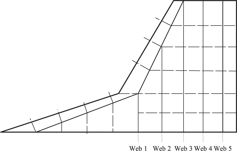
Parallel multi-web structure layout.
Thicknesses of the webs in the front wing box are 4 mm, the front web and Webs 1–5 are 6 mm, and the ribs are 4 mm. Similarly, the enhanced ribs are 6 mm as the layout 1. The skins are divided into three parts: one region in the strake and two regions in the external wing. The thicknesses are 10, 8, and 8 mm, respectively.
Analyses of two structure layouts
The static analysis was conducted for the FEMs of the wing structures. When constructing the finite model of wing, the practical problem would be simplified. The spar boom and the edge strip of the rib are discretized as a beam element or rod element. The web and skin are discretized as a panel element or shell element. The wing of aerospace plane in the article has a low relative thickness, and it is a multi-web structure. The skins mainly bear axial load. Therefore, the webs and ribs are simplified as panel elements and shell elements without edge strips. The clamped boundary condition was applied to the nodes located at the wing root.
MSC.Patran was used as the pre-processing and post-processing software, and MSC.Nastran was used as the solver. When generating the FEM of the wing structure, two-dimensional (2D) shell elements simulated the skins, webs, and ribs. QUAD4 was used in meshing for its high precision. Duralumin 2A12 was chosen as the material of the wing which was protected by the thermal protection system. On account of the thermal protection system, the temperature distribution of the load-carrying structure is also simplified. Each node in the finite model was set to the same temperature value.
Aerodynamic analysis
Figure 5 shows the typical re-entry flight state of X-37B. 14 It experienced hypersonic, supersonic, transonic, and subsonic flight. In order to contrast loading situations in different periods of the re-entry, six calculation points were chosen on its trajectory (shown in Table 1).

The typical re-entry flight state of X-37B: (a) angle of attack and (b) height.
The typical flight state of X-37B. 14

For the speed of 0.37, 0.7, 1.1, and 3.0 Ma, Navier–Stokes (N-S) equations are solved based on the cell-centered finite volume method, and the one-equation Spalart–Allmaras turbulence model is solved decoupled from N-S equations. Ansys Icem and Fluent were used to calculate the aerodynamic characters. For the speed of 7 and 20 Ma, a suitable local surface inclination method was selected to calculate the pressure distributions, which could adapt to different Mach numbers and complex shape vehicles as much as possible. 15 In 1980, DeJarnette improved the modified Newtonian method after a large number of experiments studies. This method is more consistent with the experimental results at hypersonic aerodynamic engineering prediction, and suitable for different shapes of vehicle. Figure 6 shows the surface grids and the surface pressure distributions of the wing.

Grid and surface pressure distributions for aerodynamic analysis: (a) grid for N-S equations, (b) grid for the modified Newtonian method, (c) upper surface pressure distribution for 0.37 Ma, (d) upper surface pressure distribution for 0.7 Ma, (e) upper surface pressure distribution for 1.1 Ma, (f) upper surface pressure distribution for 3.0 Ma, (g) lower surface pressure distribution for 7.0 Ma, and (h) lower surface pressure distribution for 20.0 Ma.
The pressure coefficients of the wing surface were gotten through aerodynamic analysis in different flight conditions. Then, the pressure of the wing surface was calculated by formula (1). Multiplying working load by safety factor 1.5, design load was gotten. Finally, design load was exerted to the FEMs of the wings

where p is the surface pressure,
Static analysis and comparison
At the speed of 0.37, 0.7, and 1.1 Ma, the effect of aerodynamic heating was not considered, and the elastic modulus of aluminum alloy 2A12 is 69 GPa. At the speed of 3, 7, and 20 Ma, the maximum temperature of the wing is 177°C caused by aerodynamic heating 16 and then the elastic modulus of 2A12 at 150°C is 63 GPa. 17 Poisson ratio of 2A12 is 0.3, and its density is 2700 kg/m3. Materials and properties of each part were set in attribute settings. The FEMs of two wing structures are shown in Figure 7. After static analysis in the multiple flight conditions, stress distributing graphs and displacement graphs were achieved.

The finite element models of the wings: (a) equal percentage multi-web and (b) parallel multi-web.
The results show that at the speed of 0.37 Ma and 7° angle of attack, the stress distribution is apparently different from the ones in other flight conditions. The stress distribution graph in the condition of 0.37 Ma and 7° angle of attack is shown in Figure 8. It displays that the stress distributions of the two structures are similar, whereas the stress concentration zones are in different areas. In the equal percentage multi-web wing, the maximum stress appears at the rear of wing root, and there is a stress concentration at the kink of Web 1. The reason of this phenomenon is that Web 1 changes too much at the kink. As well, the maximum stress appears at the kink in the parallel multi-web wing.

The stress distribution in condition of 0.37 Ma and 7° angle of attack: (a) equal percentage multi-web and (b) parallel multi-web.
The stress distributions and displacements in other flight conditions are similar. The results for Ma = 3 and angle of attack = 20° are shown in Figures 9 and 10. In this condition, the aerodynamic load is the most serious. In the equal percentage multi-web wing, the maximum stress appears at the root of Web 5, and it is 332 MPa. The maximum deformation is at the tip of trailing edge, which is 94.3 mm. Based on the force-transfer theory of the structure, the stiffness of Web 5 is high and the force-transfer path is short, so allocated load of Web 5 is more than the other webs. Therefore, the maximum stress appears at the root of Web 5. The force-transfer path of Web 4 is the second shortest, and the value of stress at the root of Web 4 is also high.

The stress distribution in condition of 3 Ma and 20° angle of attack: (a) equal percentage multi-web and (b) parallel multi-web.

The displacement in condition of 3 Ma and 20° angle of attack: (a) equal percentage multi-web and (b) parallel multi-web.
In the parallel multi-web wing, the maximum stress appears at the root of Web 3, and it is 292 MPa. The maximum deformation appears at the tip of trailing edge, which is 93.5 mm. The force-transfer path of each web is short, so the load is allocated according to aerodynamic distribution. The stress distributions around Web 2, Web 3, and Web 4 are relatively uniform.
The maximum stresses and displacements in each flight condition are shown in Table 2. Tensile strength of 2A12 at room temperature is about 400 MPa. At the speed of 0.37, 0.75, and 1.1 Ma, the maximum stresses of two wings are less than the ultimate strength of the material. At the speed of 3, 7, and 20 Ma, aerodynamic heating is considered, and tensile strength of 2A12 at the temperature of 150°C is about 370 MPa. 3 The maximum stresses of two wings in each flight condition are less than the ultimate strength, and the displacements are less than 10% of the half span. The weight of the equal percentage multi-web wing is 144.5 kg, and the weight of the parallel multi-web wing is 142.4 kg.
The analysis results of two wings in different flight conditions.

Comparison of two wing structures
After the static analysis, it indicates that the stress distribution of the parallel multi-web structure is more uniform and the maximum stress is smaller. Besides, its stiffness characteristic is better than the equal percentage multi-web structure, and the parallel multi-web structure has advantages in terms of weight. Finally, it comes to a conclusion that the parallel multi-web wing had better performance than the equal percentage multi-web wing in terms of mechanical characteristic and weight.
The optimization of the parallel multi-web wing
By contrast, the mechanical property of the parallel multi-web wing is better. Based on the analysis results, the thicknesses of skins, webs, and ribs in the parallel multi-web wing are optimized in order to reduce weight. The material properties cannot be changed during optimizing in Patran/Nastran, while aerodynamic heating leads to the variation of the elastic modulus of 2A12 in the hypersonic condition, which influences the wing deformation. In this article, the elastic modulus of 2A12 at the temperature of 150°C was chosen as the setting, then the thicknesses were optimized in the condition of 3, 7 and, 20 Ma, finally the strength and stiffness were checked in the condition of 0.37, 0.75, and 1.1 Ma.
Description of the optimization
Design variable. Based on the stress distribution graph, the wing is divided into five regions, as shown in Figure 11. There are design variables: the thicknesses of skins, ribs and Webs 1–5 in each region, the web thicknesses in region A, B, and the enhanced ribs at the root, kink, and tip.
Constraint. The maximum stress should be less than 370 MPa and the maximum displacement of the tip should be less than 10% of the half span.
Object function. The wing structure weighs lightest.

Division of the wing.
The optimization result and check
The comparison of the values before and after the optimization is shown in Table 3. The wing after optimization bears the load most seriously at the speed of 3 Ma. The maximum stress is 352 MPa, and it is less than 370 MPa (tensile strength of 2A12 at 150°C). The maximum displacement of the tip is 124 mm, it is less than 10% of the half span. The wing after the optimization meets the demands of strength and stiffness. The structure weight is 85.9 kg, decreasing 39.7%. By checking the strength and stiffness in conditions of 0.37, 0.75, and 1.1 Ma, the wing meets the requirements.
The optimization results.

Without consideration of load distribution, the initial thicknesses have a wide optimization margin. The load that front wing box bears is small, then the thicknesses of skins and webs in region A and B become thinner after optimization. The wing shape and structure change a lot in region B, which leads to the stress concentration and the skins are thicker than region A. The bending resistance wing box bears the main aerodynamic loads, and the bending moment at the root is the largest and lessens along the span. Therefore, the thicknesses in regions C, D, and E show a trend of decline. The structure that bears the shear in region C amounts a lot, and the ribs in region C are thinner than region D. The force-transfer paths of Web 3 and 4 are shorter; thus, the load allocated is larger. As a result, Webs 3 and 4 are thicker than other webs.
Conclusion
The equal percentage multi-web and parallel multi-web structures were designed for the delta wing with a strake of aerospace plane. The structures were analyzed in subsonic, transonic, supersonic, and hypersonic conditions using the finite element method. The analysis result shows that the force-transfer path of the parallel multi-web structure is short, and the stress is distributed uniformly. It has a better performance than equal percentage multi-web structure in terms of strength, stiffness, and weight.
Based on the parallel multi-web wing, thicknesses of skins, ribs, and webs in each region were optimized. The optimization result shows that the front wing box bears little load, and its strength requirement is low. Meanwhile, the bending resistance wing box bears main load, and the strength requirement is high.
Footnotes
Academic Editor: Filippo Berto
Declaration of conflicting interests
The author(s) declared no potential conflicts of interest with respect to the research, authorship, and/or publication of this article.
Funding
The author(s) disclosed receipt of the following financial support for the research, authorship, and/or publication of this article: This study was supported by the Fundamental Research Funds for the Central Universities (NUAA NS2016010). The support is gratefully acknowledged.