
Abstract
The connection characteristics of HSK tool holder-spindle system have great influences on machining precision and security of computer numerical control machine tools. In order to predict dynamic behaviors and avoid connection failure of HSK tool holder-spindle system, a nominal radial stiffness prediction model for HSK tool holder-spindle flange interface is constructed. Contact stress of spindle and HSK tool holder can be obtained by considering actual interference and actual clamping force. Considering elastic contact deformation, the plastic contact deformation, and two different regimes of elastoplastic contact deformation, a fractal model of nominal contact stiffness of HSK tool holder-spindle flange interface is proposed. In order to prove the rationality of the model, the tests are validated by a self-designed equipment. The effects of different parameters to the maximal permissible rotational speed, critical bending moment, and nominal radial stiffness of HSK tool holder-spindle connection system are researched. The results can be used as an instruction for the application of HSK tool holder and optimization of geometry parameters.
Keywords
Introduction
The tool holder-spindle system is an important component in computer numerical control (CNC) tools, and the dynamic characteristics of the system have great influences on the dynamic behaviors of the entire system. Tool holder-spindle interface is often an important part of the spindle system, which can directly determine the reliability and machining accuracy of the system. Contact stiffness of the interfaces has a significant influence upon the overall stiffness of the machine structures, which are responsible for up to 60% of the total compliance. 1 The tool holder-spindle interface affects the stiffness of the entire system and is the weak point. 2 Therefore, it is important to calculate the contact stiffness and improve the reliability of the HSK tool holder-spindle interface.
Much researche had been done on identifying and solving tool holder- spindle contact stiffness by experiments. Schmitz and Duncan 3 presented a coupling substructure model, which identified the stiffness, damping, and frequency response of the spindle tool holder interface by modal method combined with the least squares algorithm. Wang and Chuang 4 improved the method and identified the contact stiffness based on the frequency response function obtained from the experiment. Movahhedy and Gerami 5 proposed a contact stiffness model by considering spindle modal. However, the identification result was greatly affected by the test noise, and it was not easy to find the logical connection between the contact stiffness and surface topography. Park et al. 6 proposed a tool holder-spindle interface characteristics model using the receptance coupling method. Zhang et al. 7 proposed a dynamic response model for the spindle machine system. But the receptance of the system should be tested by the impact device. The above methods require impact measurement results and unevenness of the contact force of the interface is not considered, which cannot be used in the design stage.
The surface topography of tool holder-spindle interface changes real contact area, then contact pressure and stiffness of the interface are changed. In order to construct the interface contact stiffness model, the surface topography must be considered. Recently, some scholars have proposed the analytical model based on the fractal theory to identify the dynamic properties of the tool holder-spindle system in order to forecast the interface contact stiffness. According to the traditional quantitative statistical description of the micro-morphology, Greenwood and Williamson 8 presented a rough surface contact model. Whitehouse and Archard 9 improved the model based on isotropic, Gaussian distribution, and exponential function assumptions. However, the model accuracy was decided by the sampling length and the accuracy of measuring equipment. Weierstrass-Mandelbrot 10 presented the W-M function based on fractal theory, which was used widely in engineering. Majummdar and Bhushan 11 proposed a rough surface contact fractal model using the W-M function. Komvopoulos and Yan 12 extended the contact model to a three-dimensional anisotropic fractal surface. Miao and Huang 13 made further improvements to the fractal contact model. They found a complete fractal surface contact model instead of the asperity contact model. Results showed that the critical area of a single rough asperity is related to the proportion, and plastic-to-elastic mode transition of the asperity is consistent with the classical contact mechanics. Gao et al. 14 found an approximate model in the process of identifying the interface contact stiffness. The elastic deformation of the asperities on the interface was considered in the model. Because the contact stiffness of each asperity was different, the interface’s contact stiffness can be obtained by the sum of each asperity’s contact stiffness. Liu et al. 2 constructed a tool holder-spindle contact stiffness model according to multi-scale contact mechanics and fractal theory, in which both the elastic deformation, plastic deformation, and elastic-plastic deformation on the asperities were considered. However, the model is only suitable for general machinery tool holder (BT). HSK tool holder is used widely in high-speed cutting machine tools, which is considered to be the most suitable tool holder for high-speed cutting. The large centrifugal force at high speed causes elastic deformation of the tool holder, which changes the contact status of the interface. 15 It is important to predict contact stiffness to improve the reliability of the HSK tool holder-spindle interface. Weck and Reinartz 16 determined the maximum load capacity of HSK tool holder interfaces. Jiang et al. 17 developed a general model to solve the machined plane joint’s contact stiffness. The model was found according to multiscale fractal geometry, elastic-plastic deformation of micro-contacts. Results showed that contact stiffness of the rough surface obeyed a power-law function, which depended on the fractal parameters. However, most of the existing researches did not study the contact stiffness prediction model on high-speed HSK tool holder and spindle system. Zhou 18 analyzed the contact stiffness of the HSK tool holder-spindle system by using the finite element method. Above all, the contact stiffness prediction model of HSK tool holder and spindle considering the fractal multi-scale contact properties has not been performed.
In order to ensure high stiffness characteristics, the minimum stress of the flange surface of HSK tool holder should be larger than zero. 19 Therefore, the HSK tool holder’s stiffness is mainly decided by the flange interface contact stiffness. An in-depth research should be done for a comprehensive understanding of the flange interface contact properties of HSK tool holder-spindle.
This article presents a nominal stiffness prediction model for the HSK tool holder-spindle flange interface considering fractal multi-scale contact properties. The elastic contact deformation, the plastic contact deformation, and two different regimes of elastoplastic contact deformation will be considered. The influences of different parameters to the properties of the HSK tool holder- spindle interface are researched. The model in this article is helpful for solving HSK tool holder-spindle contact stiffness in the design process.
Contact stiffness of HSK tool holder spindle flange interface
Contact stress model
Figure 1 is a schematic of the connection between spindle and HSK tool holder. An expansion clamping mechanism is adopted. The pull rod moves under the preload force, then the elastic chuck transfers the load on the surface of the HSK tool holder. The taper surface and the flange surface between the tool holder and spindle are clamped by the mechanism. When the HSK tool holder is clamped to the spindle, contact stress between HSK tool holder and spindle can be determined by the actual interference and the actual clamping force.
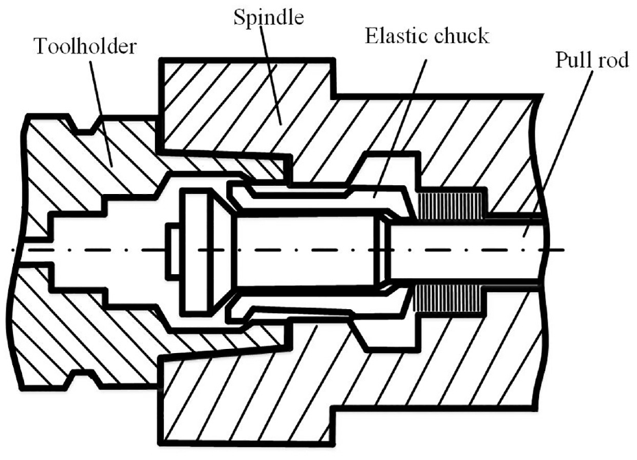
Spindle and HSK tool holder with preload.
For a hollow annulus, radial displacement with radius r is written as 20
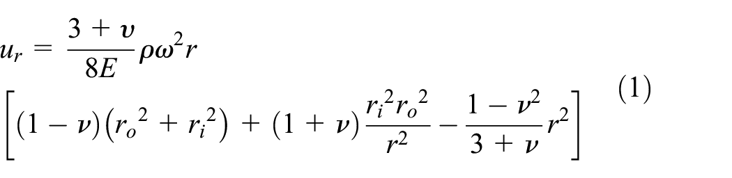
where
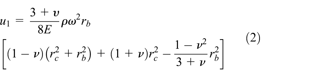
Figure 2 shows the radial section of the tool holder and spindle. The inner and outer radiuses of the spindle are rb and rc, respectively, and the inner and outer radius of the tool holder are ra and rb, respectively. The spindle and the tool holder are considered as two hollow disks. Assuming the HSK tool holder and the spindle are of the same material. According to equation (1), the radial displacements of the interface between spindle and HSK tool holder can be given as follows

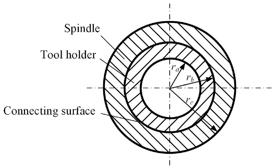
Radial section of tool holder and spindle.
The expansion deformation of the spindle causes a reduction in the actual interference between spindle and HSK tool holder. The deformation of the HSK tool holder causes an increase in the actual interference between them. Therefore, the actual interference between the taper surface of tool holder and the spindle at rotating speed ω is obtained as

where
According to the elastic mechanics theory 20 and equations (2)–(4), the contact stress due to the actual interference between the taper surface of HSK tool holder and spindle is written as

Figure 3 gives clamping force model of the elastic chuck,
21
it consists of static clamping force and dynamic clamping force. The static clamping force is determined by preload on the pull rod, as shown in Figure 3(a)). The dynamic clamping force is determined by centrifugal force under the rotating speed


Where,

Clamping force of elastic chuck: (a) static clamping force due to preload; (b) dynamic clamping force due to centrifugal force.
For HSK-A63,
Figure 4 gives the force model of HSK tool holder. Cutting force is considered. The normal force of the tool holder can be calculated as following


Where,

Force model of HSK tool holder.
Contact stress of the taper interface between tool holder and spindle due to clamping force can be written as

Then, the total contact stress between HSK tool holder taper surface and the spindle can be obtained

The contact stress between flange surface of HSK tool holder and spindle due to the normal force

Where,
Flange surface of HSK tool holder is closely attached to the spindle end face due to the clamping mechanism, which causes the high stiffness characteristics of HSK tool holder. Considering the cutting force, the bending moment M is acting on the flange surface of the tool holder.
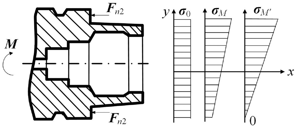
Stress distribution on flange surface of HSK tool holder.
When M = 0, the stress of the flange surface is uniformly distributed. As Figure 5 shows, the stress is equal to σ0. As the bending moment M increasing, the stress distribution becomes more and more uneven. However, as long as the distribution pressure of the edge is greater than zero, the flange surface of HSK tool holder is still in close contact with the end surface of the spindle. The maximum stress is σM, the minimum stress is larger than zero. The bending deformation of HSK tool holder is still mainly from the bending deformation of the flange. When the bending moment is further increased, the stress near the moment side will be further reduced until the edge stress is equal to zero. The maximum stress is σM,’ the minimum stress is zero. Under this condition, the flange surface starts to separate from the end surface of the spindle. Meanwhile, the bending deformation of the taper surface of HSK tool holder increases, and the stiffness of the HSK tool holder begins to decrease obviously. 19
In order to ensure the high stiffness characteristics of HSK tool holder, the minimum stress of the flange surface of HKS tool holder should be larger than zero. Therefore, HSK tool holder’s stiffness is mainly decided by HSK tool holder-spindle flange interface’s contact stiffness.
The maximum and minimum contact stress between flange surface of HSK tool holder and the spindle due to the normal force


where
If
Contact force model of asperities considering fractal multi-scale contact
The topography of the rough surface has fractal features, and the fractal properties of the rough surface can provide full roughness information on the fractal surface. The contact model can be established by using surface fractal characteristics, which ensures that the analysis results are deterministic and unique. Figure 6 shows the asperity of the rough surface.

The asperity of the rough surface: (a) rough surface; (b) deformation of contacting asperities.
A multi-scale profile can be expressed according to the W-M function 18

where
Curvature radius at the tip of the asperity is written as 2
The asperity interference can be determined by the W-M fractal function

Where, a is contact area of the asperity.
Elastic contact
The critical elastic deformation is given as 24

where K is the hardness coefficient.
Then, the critical elastic contact area can be obtained when
Assuming the maximum contact area is aL. If
For a single asperity, the normal contact stiffness is given as

Elastic-plastic contact
Kogut and Etsion
26
found that the the elastoplastic deformation of the hemisphere should divide into two stages. If
If
The elastic-plastic contact load is written as 26

Substituting equations (19), (20) and (21) into equation (26), the elastic-plastic contact load in the first elastic-plastic deformation can be written as

Then, the normal contact stiffness can be expressed as

If

The elastic-plastic contact load is written as 26
Then, substituting equations (19), (20) and (21) into equation (30), the elastic-plastic contact load in the second elastic-plastic deformation can be written as

Then, the normal contact stiffness can be given

Plastic contact
If

Total contact load and normal contact stiffness
The statistical distribution of the asperities is written as 27

Where,
Therefore, the real contact area can be expressed as

Where,

When

When
When

When

The whole normal contact stiffness of HSK tool holder-spindle flange interface can be determined by every individual contacting asperity

When

When

When

Nominal radial stiffness of HSK tool holder-spindle flange interface
Figure 7 shows the relation between normal contact stiffness and deformation of the HSK flange interface.

Contact stiffness and deformation of HSK tool holder flange interface.
Assuming the axial deformation of the flange edge are


where
Then, the nominal radial stiffness of HSK tool holder flange interface is defined as

where
In the above parameters, the structural parameters of the HSK tool holder are given. Fractal parameters D and G can be measured and identified based on W-M fractal function.
2
However, the parameter

Then, the nominal radial contact stiffness of the HSK tool holder-spindle flange interface can be determined by solving the above equations.
Analysis
Taking HSK-A63 tool holder as a research object, elastic modulus of the material
Influence on maximal permissible rotational speed
According to ISO 12164 standard, the clamping preload of the HSK-A63 tool holder is set as 18 kN, interference is set as 12 μm. Assuming bending moment M = 0. Figure 8 gives the effect of centrifugal force on the clamping force. Due to centrifugal force increases with rotation speed, the clamping force increases by 100% at 33 000 r/min. It can be concluded that the hollow HSK tool holder interface is suitable for high rotational speed conditions.

Contact stress of HSK tool holder varies with rotational speed.
As speed increases, the taper interface stress decreases while the flange interface stress increases. The maximal permissible rotational speed is defined when the taper surface stress decreases to zero. Figure 8 shows the maximal permissible rotational speed
Figure 9 gives the influence of interference and clamping preload on the maximal permissible rotational speed of the HSK tool holder.

Influence of interference and preload on the maximal permissible rotational speed: (a) influence of interference; (b) influence of clamping preload.
It can be seen that the maximal permissible rotational speed increases approximately linearly with an increase of clamping preload and the interference. The influence of the interference on the permissible speed is more significant than clamping preload. In order to increase the permissible speed, it is better by increasing the interference of the HSK tool holder-spindle. However, if the interference is too large, although the taper interface stress increases while the flange interface stress decreases obviously. In order to ensure the contact of the flange interface, the clamping preload also should be increased. This results in the taper interface stress becoming larger, which decreases the service life of the HSK tool holder. Therefore, the appropriate interference and clamping preload should be chosen, and the matching of these parameters should be careful.
Influence on critical bending moment
To ensure the high stiffness characteristics of the HSK tool holder, the minimum stress of the flange surface of the HSK tool holder should be larger than zero. The critical bending moment can be obtained when the minimum flange stress is zero. Figure 10 shows the critical bending moment increases with rotation speed. When rotating speed is 30,000 r/min, the critical bending moment is 413 N·m. This is because the actual clamping force and normal force of the flange interface increase with the rotating speed, which causes the bending moment capacity to increase.

Critical bending moment varies with rotation speed.
Figure 11 gives the influence of interference and clamping preload on the critical bending moment. It can be seen that the critical bending moment decreases linearly with an increase of interference. The critical bending moment increases linearly with an increase of the clamping preload.

Influence of interference and preload on the critical bending moment: (a) influence of interference; (b) influence of clamping preload.
The clamping force has a great influence on the increase of the critical bending moment; this is because the contact stress of the flange surface increase with the increase of the clamping preload. However, when the clamping force is too large, excessive contact stress will affect the fatigue life of the tool holder and the spindle. Therefore, an appropriate clamping preload should be selected according to the working condition.
Influence on nominal stiffness
Figure 12 gives effect of rotating speed on HSK tool holder nominal stiffness. When the bending moment is smaller than 200 N·m, the nominal stiffness does not change with the speed and the bending moment. However, the nominal stiffness decreases with the bending moment when the moment is larger than 220 N·m at 0 r/min. When the rotating speed increases to 10000 r/min, nominal stiffness begins to decrease when the bending moment is larger than 250 N·m. When the rotating speed increases to 20000 r/min, the nominal stiffness decrease when the bending moment is larger than 300 N·m, and the stiffness decreases slower. As the rotating speed increases, the high nominal stiffness range becomes larger as the bending moment increases. This is because the contact stress of the flange interface increases with the rotating speed. It illustrates that the HSK tool holder can be used at high speeds conditions. When the bending moment is larger than the critical bending moment, the nominal stiffness decreases rapidly with the increase of bending moment.

Influence of rotating speed on HSK tool holder nominal stiffness.
Figure 13 shows influence of interference on HSK tool holder nominal stiffness. The nominal stiffness decreases with bending moment when the moment is larger than 235 N·m at 10 μm. When the interference increases to 12 μm, the nominal stiffness begins decrease when bending moment is larger than 220 N·m. When the interference increases to 14 μm, the nominal stiffness begins decrease when the bending moment is larger than 190 N·m. As interference increases, high nominal stiffness range becomes smaller as bending moment increases. This is because contact stress of the flange interface decreases with the increase of interference.

Influence of interference on HSK tool holder nominal stiffness.
It can be concluded that the ability to resist external bending moments decreases as interference increases, and the nominal stiffness of the tool holder may decrease as the interference increases when the bending moment is larger than the critical value.
Figure 14 gives the influence of clamping preload on the nominal stiffness. When the bending moment is 150 N·m, clamping preload has little effect on the nominal stiffness. When the bending moment increases to 200 N·m, the nominal stiffness increases with an increase of clamping preload when the preload is smaller than 18 kN, then stiffness remains unchanged as increase of clamping preload. When the bending moment increases to 200 N·m, the normal stiffness increases with the clamping preload when the clamping force is less than 18 kN. Then the normal stiffness remains unchanged.
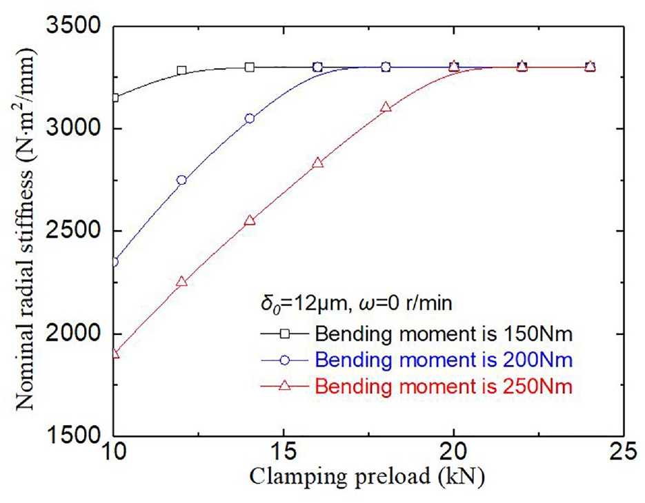
Influence of clamping preload on HSK tool holder nominal stiffness.
It can be concluded that clamping preload has little effect on the nominal stiffness when the bending moment is small. This is because a small clamping preload can ensure that the spindle is not separated from the flange surface of the tool holder when the bending moment is small. As bending moment increases, influence of clamping preload on the stiffness is more and more obvious, the stiffness increases with the clamping preload first then remains unchanged.
Therefore, under the heavy bending moment condition, increasing the clamping force can increase the nominal stiffness. However, under light-bending moment conditions, increasing the clamping force has a limited effect on increasing the nominal stiffness.
Design of interference and clamping preload
It can be seen from Figure 9 that both the interference and the clamping preload can increase the maximal permissible rotational speed of the HSK tool holder. Compare with the clamping preload, the influence of the interference on the maximal permissible rotational speed is more significant. However, Figure 11 illustrates the ability to resist bending moment decreases with an increase in interference. Meanwhile, Figure 13 explains that the nominal stiffness of the HSK tool holder may decrease as the interference increases when the bending moment is larger than the critical value. Under heavy bending moment condition, Figure 14 shows that increasing the clamping force can increase the nominal stiffness effectively. Therefore, in order to meet the requirement of the maximal permissible rotational speed, critical bending moment, and high nominal stiffness for HSK tool holder, clamping preload and interference should be designed synchronously according to the working condition.
Assuming that the rotating speed is 30000 r/min, Figure 15 gives design parameters range of interference and clamping preload of HSK tool holder. When the bending moment is 200 N·m, the interference can be designed from 8 to 20 μm, and the minimum clamping preload should be increased from 13.5 to 25 kN correspondingly. When the bending moment increases to 300 N·m, the interference should be designed from 8.3 to 15.6 μm. When the bending moment continues to increase to 400 N·m, the interference can only be designed from 8.5 to 13.5 μm. The interference and clamping preload can be chosen from the shaded range corresponding to the different bending moments.
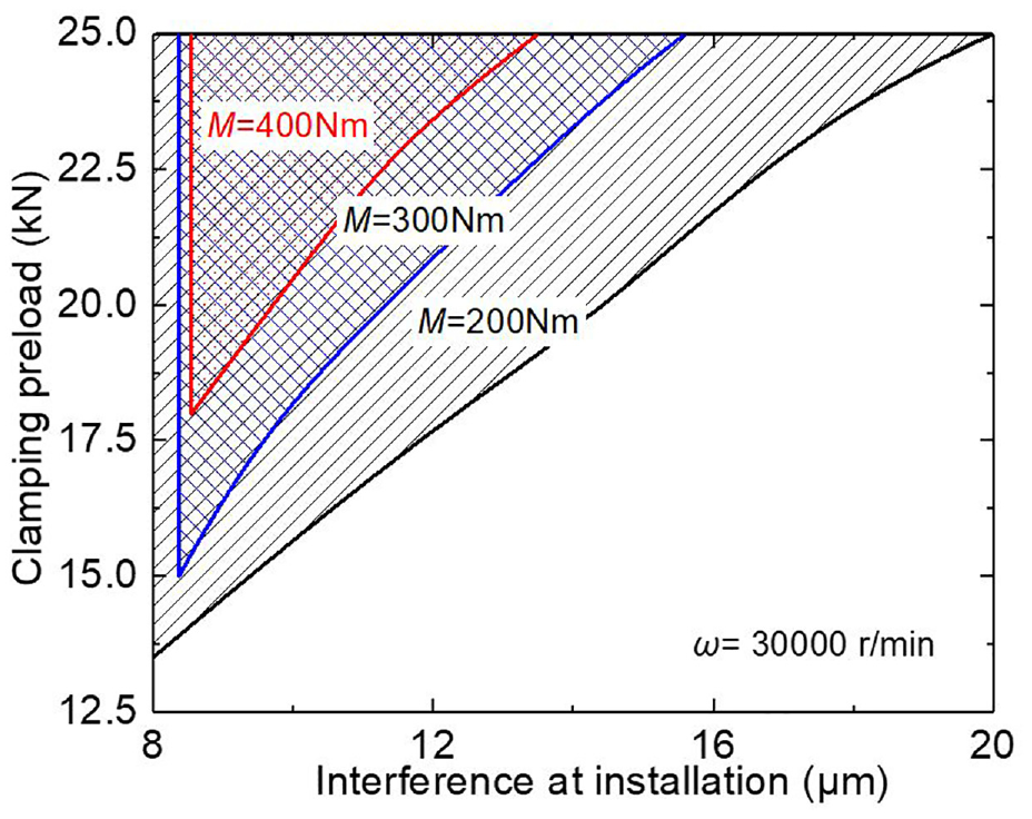
Design parameters range of HSK tool holder at 30000 r/min.
As the bending moment increases, the design range of the interference reduces and the clamping preload should be increased correspondingly. The clamping preload and interference of the tool holder should be designed carefully, especially in high speed and heavy bending moment conditions.
Experimental verification
In order to verify the method proposed above, the HSK tool holder-spindle nominal stiffness experimental setup is designed and the experiments are performed.
Figure 16 illustrates the setup of the experiment. HSK-A63 tool holder is used and the spindle is simulated. The interference can be designed by the tolerance of the simulated spindle. The clamping preload can be adjusted by the spring and measured by a BZ1202 force sensor. The cutting force is applied on the tool holder by a radial loading device and measured by a BZ1201 force sensor. Bending moment acting on the flange surface of the tool holder can be calculated according to the geometry parameters of the HSK-A63 tool holder. The axial deformations of the HSK tool holder flange edge are measured by two ZA-210803 displacement sensors. The data are sampled and analyzed based on PCI 8622 data acquisition system.

Experimental setup: (a) schematic of the tool holder experimental setup; (b) experimental setup.
The theoretical and experimental results under no-speed conditions are compared. Interference of HSK tool holder-spindle is designed as 12 μm. The clamping preload of HSK-A63 tool holder is set as 14, 18, and 22 kN, respectively. Figure 17 gives contrast of the nominal stiffness between theoretical results and experimental results.

Comparison of calculation results and test results.
From the theoretical results in Figure 17, it can be seen that the nominal stiffness remains unchanged then decreases obviously with the bending moment when the moment is larger than 150, 220, and 265 N·m, under the condition when clamping preload are 14, 18, and 22 kN, respectively. From the test results in Figure 17, it can be seen that the nominal stiffness remains unchanged then decreases obviously with the bending moment when the moment is larger than 140, 220, 250 N·m, respectively. Test results show that theoretical results are close to the experimental results, the maximum difference is 9.3%. Figure 17 verifies the method proposed in this article.
Conclusion
The prediction method for maximal permissible rotational speed of the HSK tool holder is given. The maximal permissible rotational speed of the HSK tool holder increases approximately linearly with the increase of the clamping preload and the interference. The influence of interference on the permissible speed is more significant than clamping preload. In order to increase the permissible speed, it is better by increasing the interference of the spindle-tool holder.
The critical bending moment applied on HSK tool holder is given to ensure high nominal stiffness. The critical bending moment decreases linearly with an increase of interference and increases linearly with an increase of clamping preload. The clamping force has a great influence on the increase of the critical bending moment.
As rotating speed increases, the high nominal stiffness range of the HSK tool holder becomes larger as the bending moment increases. When the bending moment is larger than the critical bending moment, the nominal stiffness decreases rapidly. As interference increases, the high nominal stiffness range becomes smaller as the bending moment increases. The ability to resist external bending moments decreases as the interference increases. Under the heavy bending moment condition, increasing the clamping force is effective for increasing the nominal stiffness.
In order to meet the requirement of the maximal permissible rotational speed, the critical bending moment and high nominal stiffness for HSK tool holder, clamping preload, and interference should be designed synchronously and carefully according to the working condition, especially in high speed and heavy bending moment conditions.
This article gives a new method to predict nominal radial stiffness for the HSK tool holder-spindle flange interface considering contact fractal and multiscale contact mechanics. The experiment proves the accuracy of the theoretical model. The model in this article is helpful in solving HSK tool holder-spindle contact stiffness in the design process.
Footnotes
Handling Editor: James Baldwin
Declaration of conflicting interests
The author(s) declared no potential conflicts of interest with respect to the research, authorship, and/or publication of this article.
Funding
The author(s) disclosed receipt of the following financial support for the research, authorship, and/or publication of this article: This work was financially supported by the National Natural Science Foundation of China (grant no. 51675323) and the key subject of Shanghai Polytechnic University (Material Science and Engineering, XXKZD1601).