
Abstract
High-speed hydrodynamic sliding bearings use lubricating oil that can have laminar and turbulent flow states, yet turbulent states remain relatively unstudied. This study combines theoretical analysis, numerical modeling, and experiments to analyze lubrication fluids in such bearings. It considers Reynolds equations, energy equations, and temperature-viscosity relationships under laminar and turbulent flows. The governing equations are solved by the finite difference method. Two-dimensional distributions of Reynolds number, pressure, and temperature in the bearing film, as well as the lubrication characteristics like bearing capacity and frictional force under working conditions, are analyzed. Single and mixed flow states are compared, which demonstrates the coexistence states of laminar and turbulent flows in an oil film under specific working conditions. Oil film flow distributions differ significantly according to rotational speed and eccentric conditions. Flow changes under high eccentricity are complex. The characteristics of oil films in a single flow state deviate significantly from those in mixed flow. Changes in flow state and heat should not be ignored during analysis of the lubrication performance of high-speed bearings.
Introduction
Fluid radial sliding bearings are widely used in various rotary machines. Their tribological properties influence the service life of the whole machine. Studies on lubrication theory under laminar and turbulent flows have achieved rapid progress since the 1960s. Lubrication theory under laminar flow is quite mature, but many problems remain under turbulent flow. Judgment of the flow state in the oil film is the primary problem. Existing studies on bearing lubrication have mainly assumed that an oil film has a single flow state (actual hypothesis); that is, simple laminar flow or turbulent flow. When calculating the Reynolds number (Re = Uρh/μ) to determine the flow state of a bearing oil film, it is generally hypothesized that the maximum line velocity of the journal (U) and the lubricating oil density (ρ) are constant. Therefore, the Reynolds number is determined by h/μ, where h is the thickness of the oil film and μ is the kinetic viscosity of the lubricating oil. For simplification, h is generally taken to be the lubricating oil film’s minimum thickness, average thickness, or bearing clearance, while μ is taken to be the oil’s minimum viscosity, average viscosity, or viscosity at the inlet.1–3 Such a simplified approach produces a single Reynolds number for the whole oil film, which has one flow regime. However, some aerospace engines and air separation units have eccentricity and/or oil chambers with different depths in their hydrodynamic, hybrid, and floating ring bearings. Therefore, h is variable, while μ also changes to different extents with temperature and pressure. As a result, the Reynolds numbers at different points in the oil film are significantly different. 4 Most existing studies hypothesize that there is a single flow state in such systems, which does not always reflect the real world. Hence, determining accurate flow distributions in oil films is important in calculating the lubrication characteristics of bearings.
In the early 1950s, Wilcock 5 found the influence of turbulence effect on the bearing characteristics in a series of experiments, thus linking the turbulence theory with the bearing. After that, Constantinescu, 6 Ng–Pan, 7 Hirs, 8 k–ε, 9 and other turbulence models have been widely used. The results of k–ε model and Constantinescu model are quite consistent with those of Ng–Pan model, 10 but the calculation process is much more complicated. Ng–Pan model is more suitable for the high-speed and light-load dynamic bearing with Couette flow as the main flow. Based on these four turbulence models, scholars in different countries have done a lot of research for different working conditions and bearing forms.11,12 Mallya et al. 13 studied the static characteristic of misaligned three-axial water-lubricated journal bearing in the turbulent regime based on the Ng–Pan turbulence model. Lv et al. 14 investigated the influence of local turbulent flow on the performance of a mixed-lubrication bearing based on the average Reynolds equation and Ng–Pan turbulence model. The results showed that local turbulence remarkably influences the friction coefficient.
In fact, with the increase of Reynolds number, there is a transition region in the transition process from laminar flow to turbulent flow, which is mainly characterized by the appearance of Taylor vortex with chaotic properties. Therefore, the study of turbulent lubrication becomes extremely complicated. 15 In the design of sliding bearing, Rec (the critical Reynolds number) is generally set. 16 When the local Reynolds number is less than Rec, the viscous force plays a leading role, and the fluid is in the laminar flow. If the Reynolds number continues to increase, the laminar flow collapses and forms vortex; when the Reynolds number exceeds Rec, the inertial force plays a leading role, and the flow regime completely changes into turbulence. In general, the critical value is different with different bearing structures. 3
In high-speed rotor systems, friction in the oil film can lead to dramatic power consumption, resulting in rapid increases in oil temperature. The excessive temperature may significantly decrease the viscosity of the oil and can cause wearing, agglutination, and heat damage 17 upon lubrication failure, resulting in loss of bearing capacity. Such heating may be increased by the occurrence of turbulent flow in the oil, which should not be ignored. 18
The lubrication equations of sliding bearings are mainly solved by numerical methods, database methods,19,20 approximation methods, 21 and computational fluid dynamics (CFD) methods.22,23 Currently, studies on the lubrication performance of sliding bearings are carried out using numerical method, which has high calculation efficiency and low cost. Common methods used in these studies include the finite difference method, finite element method, and boundary element method. Among them, the finite difference method is most widely used as it involves programming and convenient calculation. 24 CFD software is convenient for solving complicated problems but it requires verification by theoretical analysis and experimental results in most cases. The Reynolds equation was solved by a numerical method and the full Navier–Stokes equation was solved by CFD software in one study. 22 Moreover, the inertial effects of turbulence and convection fluids on water-lubricated sliding bearings were discussed.
Recently, many studies reported that setting appropriate stairs, oil chambers, or groove structures in bearing bushes are effective ways to improve the performance of bearings. Based on the Constantinescu turbulence lubrication theory, Rajasekhar et al. 25 analyzed the lubrication performance of hybrid sliding bearings with four different shapes of the chamber (square, round, oval and triangle) using the finite element method. Numerical calculations demonstrated that turbulent flow and oil chamber shape could significantly affect bearing performance. Rahmani and Shirvania 26 comprehensively analyzed the static parameters of the Rayleigh step bearing based on laminar theory. They determined the optimal structural parameters of the bearing through optimization, thus obtaining the maximum bearing capacity or minimum frictional force. Heinrichson et al. 27 constructed a three-dimensional mathematical and physical model of thermoelastic flow based on the basic governing equation and analyzed the influences of oil chambers on the performance of a tilting-pad thrust bearing. Shenoy and Pai28,29 solved the Reynolds equation by the finite difference method based on the Ng–Pan turbulence insulation model and analyzed the static and dynamic characteristics of a sliding bearing with an oil film of adjustable thickness. Li et al. 30 analyzed the thermal lubrication performance of a cone hybrid bearing with a deep oil chamber based on turbulent lubrication equations and gained three-dimensional pressure and temperature field distributions on the oil film through a numerical method.
These studies have made useful progress in the understanding of bearing lubrication. However, most have neglected changes in Reynolds number and assumed that oil films have single flow regime. Nevertheless, a few studies on possible “mixed flows” and associated bearing characteristics have been reported. In this study, first, the existence of mixed flows in an oil film under specific working conditions was verified by theoretical analysis. Second, pressure and temperature distributions in an oil film in a sliding bearing under mixed flows were investigated using numerical and experimental methods. The lubrication characteristics like bearing capacity and frictional force were also estimated. Finally, the mechanisms of influence of the main shaft speed and bearing structure on oil film characteristics were analyzed.
Flow state criterion, governing equations and boundary conditions
Flow state criterion of oil film
Reynolds number was used to represent the flow characteristics of the viscous fluid, which was calculated as Re=Uρh/μ. Whether the fluid was in laminar flow or turbulent flow was determined by comparing the calculated Reynolds number and the critical Reynolds number (Rec, Rec = 41.1(r/c)0.5, where r is the journal radius and c is the clearance radius). The flow is laminar when Re<Rec and is turbulent when Re≥Rec. In this study, the influences of flow state in the transition zone were neglected.
Reynolds equations
The Reynolds equation is the basic equation of fluid lubrication theory. The lubricating oil is assumed to be an incompressible Newtonian fluid and the influences of inertial force are neglected. The journal axis in the process of bearing rotation is always parallel to the bearing axis.
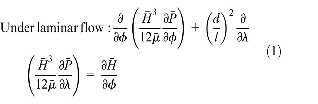
The two-dimensional dimensionless Reynolds equation under laminar flows can be deduced from reference 3
The two-dimensional dimensionless Reynolds equation under turbulent flows can be deduced based on the Ng–Pan model 7

where
Energy equations
The temperature distribution in an oil film is an important factor that influences lubrication performance. It is necessary to obtain the temperature distribution to solve the energy equation. In this study, deduction of the energy equation was based on the following basic assumptions: (1) adiabatic flow, (2) lubricating oil at the inlet had a low temperature, and (3) the lubricating oil had constant density and specific heat values. Viscosity is a function of temperature; hence,
Under laminar flow

Under turbulent flow
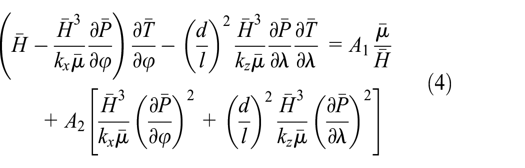
where A1 = 2μ0Ur/(ρcvT0c2), A2 = A1/4, and cv is the specific heat of the lubricating oil.
Boundary conditions
The Reynolds equation is solved for a given pressure boundary condition, in this case, the Reynolds boundary condition. The bearing structure is shown in Figure 1. The fuel supply pressure in dynamic sliding bearings is generally small. Hence, the pressure was set as zero at the inlet boundary. The two axial ends of the bearing contact with the external boundary and the pressure are set to 0. The end-side of the oil film is at a point in the divergence region behind the minimum thickness in the convergence clearance. At this point, the pressure and pressure gradient are both set to 0. The pressure boundary conditions are as follows 3


Structure of the bearing.
Since the end-side of the oil film cannot be determined in advance, it has to be calculated through iteration, and the effects of the oil chamber are also considered, thus increasing the calculation difficulty.
The boundary condition of the energy equation is

Pressure and temperature are continuous at the boundary between the oil chamber and sealing side, and positions with changing flow state.
Temperature-viscosity relationship
Generally, viscosity and the temperature-viscosity relationship significantly influence the hydrodynamic lubrication ability of a fluid. Moreover, viscosity affects the Reynolds number directly, thus influencing the judgment of the flow state. Common temperature–viscosity relationships include the Reynolds temperature–viscosity equation, Slotte temperature–viscosity equation, and Vogel temperature–viscosity relation equation. In this study, the more convenient Reynolds temperature-viscosity equation was applied in the numerical calculation and was transformed into a dimensionless form

where T0 is the lubricating oil temperature at the inlet. Although a low T0 will decrease the peak oil temperature, the oil temperature is low and viscosity is high, which increases resistance in the lubricating oil transport lines. Hence, lubricating oil must be preheated to the regulated initial temperature before entering the bearing to ensure appropriate flow. In the study, T0 = 40°C.
Oil film thickness equations
Here, a rigid model was applied as the lubrication model. Since the clearance radius (c) is far smaller than the journal radius (r), the oil film thicknesses at the sealing side and in the oil chamber are different:


where
Simulation of the lubricating properties of a sliding bearing
Solving the governing equations
In this study, equations (1)–(11) were solved by the finite difference method. Due to the presence of oil chambers on the bearing bush, the oil film thickness changed gradually along the circumferential and axial directions. To avoid thickness inconsistencies at discrete nodes, the model’s grid size was determined according to the size of the oil chamber to ensure that the boundary between the oil chambers fell on a grid line.
Equations were solved by loose iteration methods based on MATLAB software. According to the boundary conditions, initial values of pressure, temperature, and viscosity were assigned to different boundary nodes. The pressure at all internal nodes was set to zero at the first iteration. New values of pressure at each node were calculated and used to replace the old values. Pressures at nodes with P < 0 were set to zero and brought into the energy equation and temperature-viscosity equation, thus obtaining approximate values of temperature and viscosity at different nodes. Iterations continued until the predetermined convergence accuracy was achieved.
Analysis of bearing lubrication properties
The section discusses the relationships between the lubricating properties of the sliding bearing’s oil film (e.g. Reynolds number, pressure, temperature, and bearing capacity) and rotational speed and eccentricity ratio.
A radial hydrodynamic sliding bearing with four oil chambers was used as the research object. The middle plane of the bearing and the structure of the unfolded bush are shown in Figure 1. Four identical oil chambers were opened uniformly on the bearing bush along the circumferential direction and the space between any two oil chambers was on the sealing side. The basic structural size was manifested as the radius of the journal (r = 50 mm), radius clearance (c = 0.30 mm), width–diameter ratio (l/d = 1), wrap angle of the oil chambers (φb = 45°), axial dimensionless width (λb = 1.6; total axial width of the bearing was 2), and oil chamber depth (hb = 0.05 mm). The lubrication parameters included oil supply temperature (T0 = 40°C), temperature–viscosity coefficient (α = 0.032 K−1), viscosity of lubricating oil at 40°C (μ0 = 0.0384 Pa s), density (ρ = 860 kg/m3), and specific heat (cv = 1600 J/kg K). Working parameters included the journal rotational speed (n = 15,000–25,000 r/min) and eccentricity ratio (ε = 0.1–0.8). It was calculated that the critical Reynolds number was Rec ≈ 580.
The distributions of Reynolds numbers on the middle plane (λb = 1) when ε = 0.7 and n = 18,000 r/min are shown in Figure 2. Obviously, the circumferential distributions of Reynolds numbers under the two conditions are similar and show an evident gradient at the oil chamber boundaries. The oil film is in the mixed flow state. As shown in Figure 2(a), when n = 15,000 r/min, the position of

Distribution of Reynolds numbers at different rotational speeds and eccentricity ratios: (a) distribution of Reynolds numbers (ε = 0.7) and (b) distribution of Reynolds numbers (n = 18,000 r/min).
The circumferential pressure distributions on the middle plane when ε = 0.7 and n = 18,000 r/min are shown in Figure 3(a) and (b). When the eccentricity ratio is fixed, the pressure at different points in the oil film is positively related to rotational speed. The pressure at the border between the oil chambers and sealing side is continuous, but the pressure gradient is discontinuous. With convergence clearance, the pressure of the oil film increases gradually. With diffusion clearance, the oil film bears a high load and is broken quickly. When the rotational speed is fixed, the wedge contraction effect is evident under high eccentricity ratios (ε = 0.7 and 0.8). The influences of the oil chambers are weakened and the gradients in the pressure distribution curves are covered. When the eccentricity ratio is small (0.3–0.6), the influences of the oil chambers are strengthened and the pressure curve at the border between the oil chambers and sealing side has an obvious change. Since the oil film has been broken when ε = 0.1 and 0.2, the pressure peak is decreased. The calculated pressure distributions under single laminar flow and turbulent flow when n = 18,000 r/min are shown in Figure 3(c) and (d). The actual flow distribution is neglected. The pressure distribution in Figure 3(c) is slightly smaller than that in Figure 3(b). The pressure peak at ε = 0.8 is 6.7% lower. In Figure 3(d), the pressure distribution is slightly higher, with the pressure peak at ε = 0.8 being 14.6% higher.
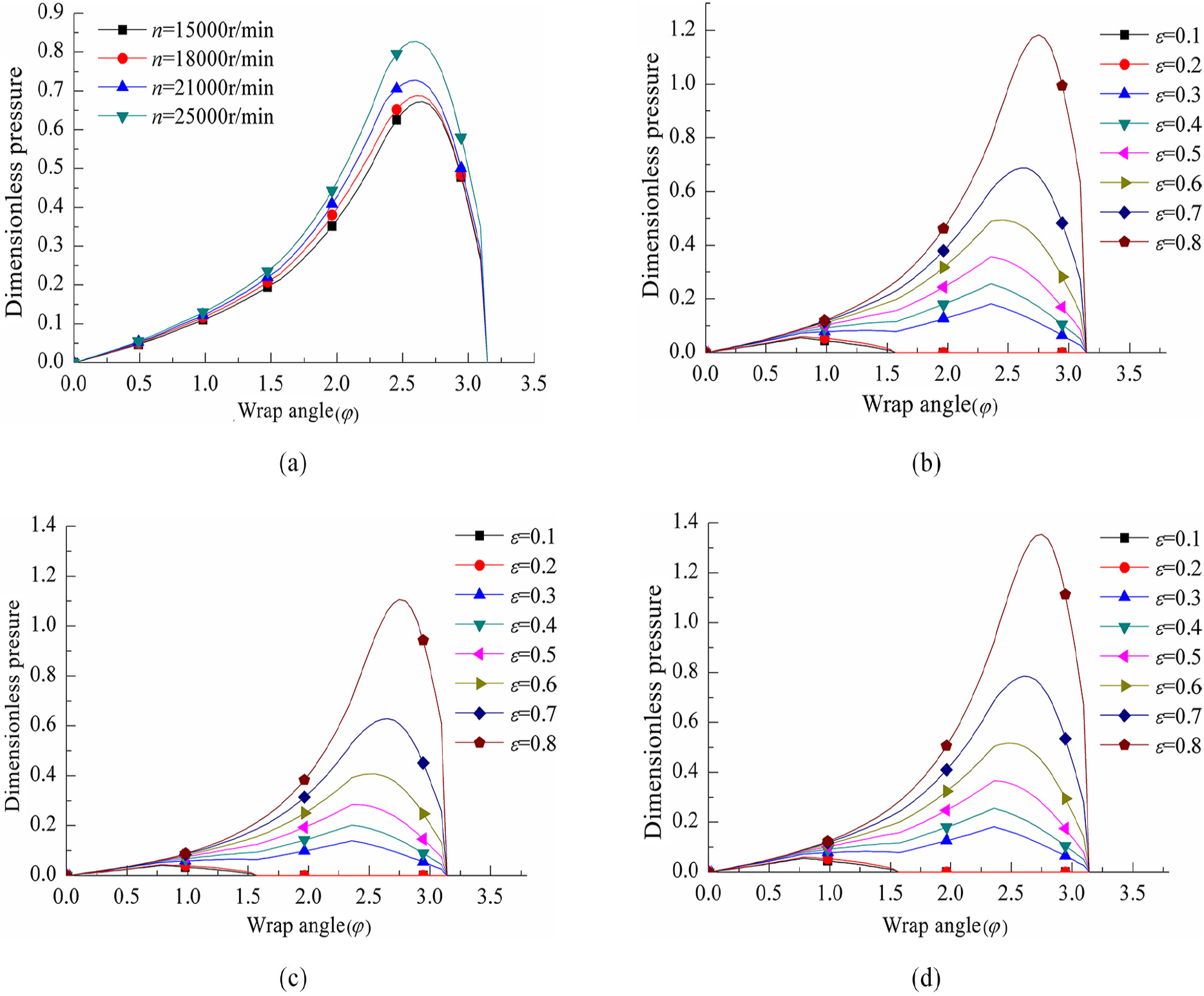
Distribution of pressure at different rotational speeds and eccentricity ratios: (a) curves of pressure at different rotational speed with ε = 0.7, (b) curves of pressure at different ε with rotational speed of 18,000 r/min, (c) curves of pressure of single laminar flow with rotational speed of 18,000 r/min, and (d) curves of pressure of single turbulent flow with rotational speed of 18,000 r/min.
The circumferential temperature distributions on the middle plane when ε = 0.7 and n = 18,000 r/min are shown in Figure 4(a) and (b). A temperature gradient is observed. However, in the turbulence governing equation, the influences of the turbulence factor on pressure and temperature are small due to the small Reynolds number occurring in this working condition. Hence, such pressure and temperature gradients are not obvious. The minimum temperature occurs at the inlet and the maximum temperature occurs at the breakage of the oil film. This is because, in the energy equation, oil film temperature is inversely proportional to thickness. When the eccentricity ratio is fixed, the viscous shear effect in the oil film is strengthened as the rotational speed increases and the oil temperature increases accordingly. When the rotational speed is fixed, the temperature peak is higher under the higher eccentricity ratio. These distribution characteristics are consistent with the stepped bearing characteristics in Pinkus and Sternlicht. 21 The temperature distributions calculated under single laminar and turbulent flows when n = 18,000 r/min are shown in Figure 4(c) and (d), respectively. The calculated temperature under single laminar flow is slightly higher than that in Figure 4(b). Of course, the actual flow state in the bearing is basically single turbulent flow when ε = 0.1–0.4, which is naturally similar to the results calculated under single turbulent flow.
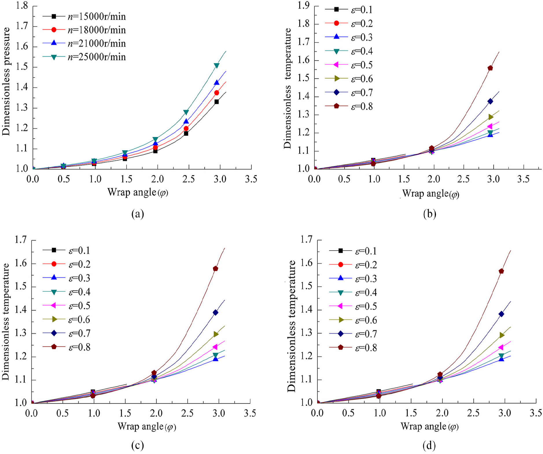
Distribution of temperature at different rotational speeds and eccentricity ratios: (a) curves of temperature at different rotational speed with ε = 0.7, (b) curves of temperature at different ε with rotational speed of 18,000 r/min, (c) curves of temperature of single laminar flow with rotational speed of 18,000 r/min, and (d) curves of temperature of single turbulent flow with rotational speed of 18,000 r/min.
The lubrication characteristics including bearing capacity, frictional force, lateral discharge, and peak temperature on the middle plane of the oil film at various rotational speeds (15,000, 18,000, 21,000, and 25,000 r/min) and eccentricity ratios are shown in Figure 5. These results are compared with the corresponding parameters of a cylindrical sliding bearing without oil chambers under the same conditions. In Figure 5(a), (c), and (d), the left side shows the relevant curves for a bearing with oil chambers, while the right side shows those for a cylinder bearing. In Figure 5(b), the upper part is for a bearing with oil chambers and the lower part is for a cylinder bearing.

Effects of rotational speed and eccentricity ratio on the static characteristics of the bearing: (a) bearing capacity, (b) frictional force, (c) lateral discharge, and (d) peak temperature.
When the eccentricity ratio is fixed, the degree of turbulence in the oil film increases with rotational speed. At the same time, the bearing capacity increases slightly. When the rotational speed is kept constant, the bearing capacity increases greatly with the eccentricity ratio. Influenced by the positions of the oil chambers, the bearing capacity of a bearing with oil chambers is slightly lower than that of a bearing without oil chambers in most cases. The bearing capacity of a bearing with oil chambers at low rotational speeds and small eccentricity ratios is slightly higher. Of course, the bearing capacity of the oil film is lower when ε = 0.1 and 0.2, which is attributed to the smaller integral region. The frictional forces of the two bearings show complex and dissimilar variations, which are mainly caused by the influences of turbulence flow. In a word, the frictional force is positively related to rotational speed. Under different eccentricity ratios, the irregular movement of fluid molecules is more violent and the frictional force is stronger at a higher turbulence degree. The frictional force of the bearing with oil chambers is smaller than that of the bearing without oil chambers at high rotational speeds. The lateral discharge distributions of the two bearings are similar due to the small difference in the axial pressure gradients at different points. Given the same rotational speed, the axial pressure gradient and lateral discharge are positively related to the eccentricity ratio. Since the bearing with oil chambers has a high turbulence degree and large turbulence area under the same conditions, the oil temperature increases more quickly and, thereby, the viscosity of the lubricating oil declines more than that of the bearing without oil chambers. As a result, the temperature increase is inhibited. The temperature of the bearing with oil chambers is lower than that of the cylinder bearing without oil chambers.
In summary, the rotational speed of the journal and the eccentricity ratio can influence the static characteristics of a sliding bearing with oil chambers to different extents. Given the same rotational speed, the oil film changes from single turbulent flow to mixed flow in response to increases in the eccentricity ratio. Consequently, the bearing capacity of the cylinder bearing without oil chambers decreases slightly. Moreover, the frictional force and temperature decrease to different contents under most working conditions examined in this study. For example, the temperature and frictional force decrease by 8.35% and 10.29%, respectively, at n = 21,000 r/min and ε = 0.5, whereas the bearing capacity decreases by 5.83%.
Experiment to investigate the static characteristics of sliding bearings
This experiment was performed on a V600 upright CNC milling machine (Figure 6). The speed of the journal was controlled by changing the output rotational speed of the machine’s main shaft. The bearing bush was a cylinder made of organic glass with good transparency and a single bottom surface. It was compressed onto the workbench by a steel flange. In the experiment, the main shaft was made of extra super duralumin alloy bars and was installed on the main shaft of the milling machine. The region size under different flow states was measured by the axial and circumferential calipers on the glass bush.

Photographs of the test bed.
In the experiment, the diameter of the main shaft was 110 mm and its width-diameter ratio was 0.9. The inner diameter and wall thickness of the bush were 130 and 10 mm, respectively. One deep oil chamber and one shallow oil chamber were present on the inner wall. The corresponding circumferential wrap angles were 15° and 50°, and their depths were 0.3 and 0.05 mm, respectively. The axial width was 70 mm. The edges of the deep and shallow oil chambers transited through the sealing side. The corresponding wrap angles of the two sides were 15° and the axial width was 120 mm. As the main shaft had a large diameter, to avoid it contacting the bushes at each side when it approached the oil chamber, the sealing side was cut slightly in the interference zone (Figure 7). The lubricating oil used oil for the L-AN5 total loss system.

Processing of the bearing bush.
In the experiment, flow changes in the oil film were recorded by a high-speed camera through the bubble tracing method. The main shaft rotated quickly and the lubricating oil was brought into the working area between the journal and bearing, forming liquid lubrication. The oil chamber close to the bearing bush was pushed slowly to simulate eccentricity of the journal and bush in the sliding bearing. Flow state changes in the oil film were observed and measured by increasing the rotational speed of the main shaft. Meanwhile, images were collected carefully.
Flow state analysis of oil film
Changes in the oil film state with main shaft speed increase at the minimum clearance (cmin = 0.2 mm) are shown in Figure 8. It can be seen from Figure 8(a)–(h) that the speeds of the main shaft were 500, 600, 700, 800, 900, 1000, 1100, and 1200 r/min, respectively.

Variations in oil film flow state with rotational speed: (a) n = 500r/min, (b) n = 600r/min, (c) n = 700 r/min, (d) n = 800 r/min, (e) n = 900 r/min, (f) n = 1000 r/min, (g) n = 1100 r/min, and (h) n = 1200 r/min.
In Figure 8(a) and (b), small bubbles entered from the two ends of the bearing to form a gradual distribution in the deep oil chamber that shrunk gradually toward the axial center. This is similar to the fluid’s speed distribution in the space between the two parallel plates. 3 Under this circumstance, the rotational speed and Reynolds number of the oil film are relatively small and the flow is relatively stable. In Figure 8(c) and (d), the movement of bubbles in the deep oil chamber gradually becomes violent. The bubble belt in the middle region is narrowed due to the interference of cavitation. In Figure 8(e), the Reynolds number is further increased. The Reynolds number in the deep oil chamber is about 481, which is significantly higher than the critical Reynolds Number (439). Moreover, the flow of bubbles is unstable and turbulent flow occurs. The lubricating oil at the upper axial end is discharged downward due to the effect of gravity and joins with the lubricating oil drawn in at the lower axial end, producing some vortexes. These vortexes are lifted gradually and integrated into big bubbles. The oil film at the border between the deep and shallow oil chambers thickens suddenly. The shape of this zone is similar to that of the sliding valve port. It was pointed out in Zhang et al., 33 that the critical Reynolds number in this region is about 260, while that in the shallow oil chamber is only slightly different at about 240. In a region about 25 mm in length, bubbles are stretched and occur alternately. After this region, the critical Reynolds number is 621, indicating that the flow is stable and laminar. In Figure 8(f)–(h), the Reynolds number in the deep oil chamber is high and bubble flow is disordered and violent. The gradient distribution deforms gradually. In the same time, the bubble strips in the shallow oil chamber change greatly, jumping vertically and diffusing gradually to the whole clearance. With increases in rotational speed, the turbulent region expands significantly and strong turbulence occurs in the oil film.
Based on the above results, laminar flow (in the shallow chamber) and turbulent flow (in the deep chamber) coexist in the bearing’s oil film under certain working conditions. Multiple flow states occur in a region between the deep and shallow chambers. It proves that the theoretical basis of the numerical method is correct, which is in line with the actual flow phenomenon and the criterion of flow regime transition.
Measurement of the pressure and temperature
Five pressure measuring and temperature measuring holes are respectively processed on the outer wall of the bearing bush. The marks are A, B, C, D, and E, which are in the deep chamber, the junction of the deep and shallow chamber, shallow chamber, the junction of the shallow chamber and the sealing side and the sealing side, respectively. 18 mm below point A is the oil inlet, and the oil return hole is set at the bottom of the bearing to facilitate the circulation of oil. The location is shown in Figure 9. After the flow is stable, the pressure gauge and thermometer are used to measure the oil film pressure and temperature successively.

Sketch of the measuring points of pressure and temperature.
Figure 10 shows the changes in pressure of the five pressure measuring holes of the minimum radius clearance (cmin) of 0.05 mm and 0.07 mm when n = 1100r/min. Mixed flows were verified under both the experiment and numerical modeling analysis conditions in the oil chambers. When the minimum radius clearance (cmin) is constant, the pressure increased rapidly at the first two points, and then getting eased at the third point. After that, the pressure increased slightly due to the wedge contraction effect. In other words, smaller minimum radius clearance (cmin) means bigger eccentricity ratio and more obvious wedge contraction effect, which results in bigger pressure values. These experiment results are in line with the numerical analysis.

Variations of the pressure with circumferential length.
Figure 11 shows the changes in temperature of the five pressure measuring holes of the minimum radius clearance (cmin) of 0.05 mm when n = 1100 r/min with the initial oil inlet flow temperature of 27°C and the ambient temperature of 17°C. It can be seen that temperature of the oil film rises with the increase of circumferential length, which is roughly consists of the numerical calculation. The experiment values are slightly lower than the numerical calculation values due to the influence of the ambient temperature.

Variations of the temperature with circumferential length.
Conclusion
The experimental results indicate that coexistent laminar and turbulent flows developed in the oil film under certain conditions. In addition, a region of mixed flows formed at the border between the deep and shallow oil chambers. This strongly demonstrates the existence of the proposed mixed flows, as well as good consistency between actual flow phenomena and flow transformation. In general, the pattern of pressure and temperature distribution obtained are similar to those results in numerical calculation in this article.
The oil chambers were opened on the bearing bush, which is equivalent to increasing the oil film thickness in the oil chamber, resulting in increases in Reynolds number. There was an evident gradient in the Reynolds number distribution. Pressure and temperature were continuous at the border between the oil chambers and the sealing side but the gradient was discontinuous. The pressure and temperature distribution curves had clear changes at this border. The pressure curve at the transition from laminar to turbulent flow showed a change indicative of mixed flow.
Under the working conditions examined in this study, the bearing capacity of the bearing with oil chambers was slightly lower than that of the bearing without oil chambers. However, the frictional force and temperature declined to different extents in most cases. Hence, evaluations of bearing structure and performance should consider such parameters.
In this article, it is shown that the static characteristics of the oil film calculated in a single laminar flow or a single turbulent flow, without considering the actual distribution of the flow regime, are different from those calculated in accordance with the actual flow states. On the premise of acceptable calculation accuracy and scale, accurate judgment of oil film flow regime can make the calculation result more accurate and reliable.
Footnotes
Handling Editor: Liyuan Sheng
Declaration of conflicting interests
The author(s) declared no potential conflicts of interest with respect to the research, authorship, and/or publication of this article.
Funding
The author(s) received no financial support for the research, authorship, and/or publication of this article.