
Abstract
This article proposes a numerical analysis for performance improvement of the stack, which represents a crucial element on the solar-powered thermoacoustic refrigerator. The stack is considered as a saturated parallelepiped homogeneous porous media. Numerical simulation of the flow and the heat transfer in the thermoacoustic refrigerator is carried out. The physical flow is governed by the modified Darcy–Brinkmann–Forchheimer model. The governing equations are solved numerically using the lattice Boltzmann method. Furthermore, the local thermal equilibrium assumption is applied to examine heat transfer. Particular attention is paid a new form of the lattice Boltzmann equation system describing the flow and the heat transfer in porous media and fluid regions. The effects of several parameters characterizing the thermal behaviour in the porous medium are studied. The parametric results lead to the optimization of the porous media form. The presence of the viscous dissipation term in the heat transfer formulation within the thermoacoustic system is particularly highlighted, due to its significant effects introduced by the Eckert number.
Introduction
Throughout the last decades, researchers have tried to turn all the systems towards green energy, in order to become environmentally friendly.1–6 Because of high energy consumption of conventional refrigerator, the exploitation of renewable energy is an appropriate solution to increase the overall efficiency. Therefore, the thermoacoustic refrigerator (TAR) is proposed 7 (known as the thermoacoustic cooler or the thermoacoustic heat pump), as one of the recent advances in the field. The operating principle of the TAR is to convert acoustic energy into a temperature difference. 8 Generally, the operating gas used in thermoacoustic systems is either binary mixtures of rare gases that are harmless to the environment, 9 or sometimes, the ambient air itself thanks to its low cost and availability.
In 1777, Byron Higgins was the first scientist who observed the thermoacoustic effect. 9 In fact, he noticed that the heat may induce acoustic oscillation (sound). Later in 1896, Lord Rayleigh 10 gave his first qualitative interpretation for the Sondhauss tube operation. However, the inverse physical phenomenon, which is the creation of a temperature gradient from an intense acoustic wave, was demonstrated in the work of Merkli and Thomann 11 in 1975 and Wheatley et al. 12 in 1983. Since that discovery, the scientific research in thermoacoustic engines started to have concrete applications.13–15 Nevertheless, industrialization and marketing were not possible because of low efficiency. 16 One of the solutions found to enhance the TAR efficiency is to couple it with a green energy source. Recent researches proved that photovoltaic and wind energy are the lowest cost technologies used to produce electricity from renewable resources.17,18 Therefore, combining TAR and the photovoltaic system should be worthwhile. Coupling TAR and solar energy has already been studied in recent research papers13–16,19 particularly in the thermo-driven TAR case. The solar-powered TAR is studied in detail by N Yassen. 20 Moreover, he designs a stand-alone power system to feed a sinuous wave generator, which produces a standing wave in the thermoacoustic resonator. T Konaina and N Yassen 21 focused on the TAR for domestic usage powdered by solar energy. Consequently, they developed a computer code provides the system dimensions and the optimal design pressure as a function of the cooling capacity to ensure a convenient sound power. The code showed good reliability by comparing its results with some manufactured systems.
A detailed explanation of the operating mode of thermoacoustic systems was provided by Swift. 8 TAR has a simple architecture without moving parts, which makes it robust and reliable. In addition, it offers opportunities for production and miniaturization at low cost. It consists of four components: the resonator, the gas filling the resonator, the loudspeaker and the stack (called regenerator). Since the stack is the most crucial part of the TAR, particular attention will be paid to its improvement. The stack geometry is generally formed by thin plates, hence its name. Adeff et al. 22 experimentally proved the efficiency of using the porous medium (reticulated vitreous carbon (RVC)) as the core of thermoacoustic prime movers and refrigerator. Furthermore, the RVC is a low-cost solution, and its manufacture simplicity makes its usage suitable for all types of thermoacoustic devices. The RVC was simulated in previous works as a porous media.16,22 Syeda H Tasnim et al. 23 proposed an analytical study of the velocity and the temperature fields in a stack composed of parallel plates where the gaps between them are filled by porous media.
The discretization method used in this article is the lattice Boltzmann method (LBM) due to its low simulation time, its simplicity and accuracy. 24 The LBM was used in previous work, on one hand, in the simulation of the TAR 25 and, on the other hand, in the simulation of the flow and the heat transfer in porous media. Therefore, the LBM is chosen in this article to simulate the TAR having a porous media as a stack. Indeed, the LBM was adopted to analyse the heat transfer in the TAR. 25 In the same work, the software ‘PowerFLOW’ was applied, which is based on the LBM to simulate the TAR with a stack formed of parallel plates. The LBM proved its performance in thermoacoustic systems. Besides, many research papers proved the performance of the LBM in the simulation of flow and heat transfer in porous media. For these reasons, the LBM was applied to simulate flow and heat transfer inside TAR having a porous media stack.
The main objective of this article is to investigate the viscous dissipation inside the porous stack. Conjugate problems, including the viscous fluid and the porous medium, are among important troubles for a whole bunch of technologies. For instance, air heaters, solid matrix, heat exchangers, electronic cooling, drying processes 26 and pulse tube cryocooler 27 are exposed to this kind of issues. In fact, enhancing heat transfer is the major advantage of porous media.28–31
However, the detailed description of the flow and thermal fields of the acoustic waves, inside the thermoacoustic stack, modelled as a porous media, are not available in the literature concerning a rectangular resonator. In this work, we developed a mathematical model of the fluid motion and the heat transfer in three parts of the solar-powered TAR. Then, a new formulation of the Lattice Boltzmann equations is presented, describing the flow and the heat transfer in both porous media and fluid regions. Furthermore, a numerical study is carried out to investigate the effect of some relevant parameters on the thermal performance of the solar-powered TAR. These parameters include the Darcy number, the porous media porosity, the heat capacity ratio, the heat conductivity ratio and the Eckert number. The remainder of this article is organized as follows: section ‘Problem specification’ defines the problem specifications, section ‘Validation’ depicts the validation procedure, section ‘Results and discussion’ is devoted to results and discussion and section ‘Conclusion’ concludes the article.
Problem specification
The system consists of a TAR powered by grid-connected photovoltaic panels as shown in Figure 1(a). The photovoltaic panel produces direct current (DC) that is converted into alternating current (AC) using the inverter, Indexed 2 in Figure 1(a). Two power metres are used to record the power generated by the photovoltaic panel and the power absorbed by the TAR. On a sunny day, the refrigerator consumes the electric energy generated by the photovoltaic panel. However, on cloudy days or at night, the TAR is powered by the grid. Moreover, the extra produced electricity by solar panels is sold to the power company. The loudspeaker converts electric power into acoustic power. The latter is then transformed into a temperature difference that can be explored in different ways such as refrigeration appliances or biomedical devices.

Schematic diagram ((a) of the system and (b) of the thermoacoustic refrigerator).
In this investigation, the simulation only concerns the TAR. The photovoltaic panel sizing is devoted to future works. To this end, the TAR is designed according to a two-dimensional model as shown in Figure 1(b). The basic components of the system are the resonator, the loudspeaker and the stack. The resonator is a quarter wavelength tubes whose boundaries are exposed to the ambient temperature. The resonator has a closed extremity on the right side as shown in Figure 1(a). In the left resonator’s extremity is located a loudspeaker, ensuring acoustic power. The resonator is filled by air under atmospheric pressure where the Prandtl number is equal to 0.71, and the average temperature Tm is equal to 300°K. The fluid is animated by the wave emitted from the loudspeaker. The resonance frequency of the tube is 200 Hz. The crucial part of the TAR is the stack which is made from a homogeneous porous medium. The stack centre is located at the position x = xc and the stack length is ls, as shown in Figure 1(b). The values of ls and xc change throughout the article.
Governing equations
The governing equations, characterizing describing the flow and the heat transfer inside the TAR, are presented in the following section. It is worth noting that the local thermal equilibrium between the fluid and the solid phases assumption is taken into consideration in this article. The thermophysical properties of the fluid are constant, the fluid is assumed to be low compressible and the porous medium is homogeneous, isotropic and saturated.
A binary parameter is used to write the equations for both sections, fluid and porous, in a unified way. The binary parameter Θ is defined as32,33

Based on the previous assumptions and the binary parameter (equation (1)), the mass, the momentum and the energy equations are written as follows23,33,34
Continuity equation

Momentum equation

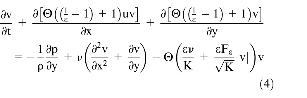
Energy equation

where u, v, p and T are the axial and the transversal velocity components, the pressure and the temperature, respectively.
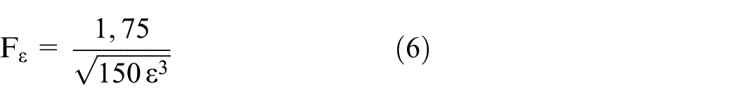
ρ, ν, α, Cp, k, ε, K and Fε are the density, the kinetic viscosity, the thermal diffusivity coefficient, the heat capacity, the heat conductivity, the porous media porosity, the permeability and the Forchheimer number, respectively. Subscripts ‘s’ and ‘f’ design the porous media and the fluid part of the solid matrix, respectively. Fε is defined as follows
Dimensionless governing equations
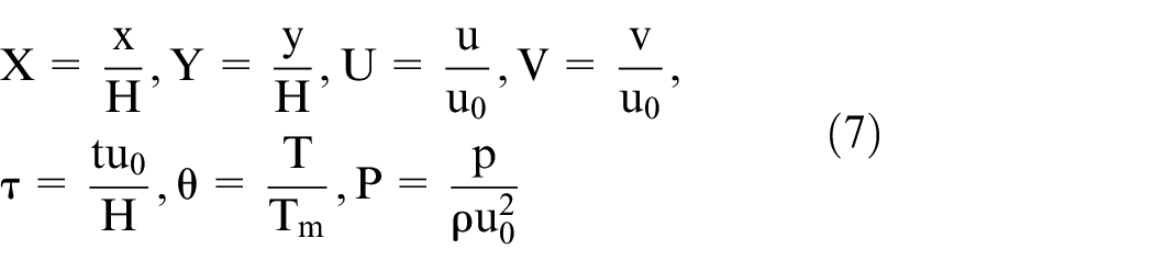
The dimensionless governing equations authorize the introduction and the study of similar problems with the same dimensionless parameter. The dimensionless reference quantities are defined as
The dimensionless governing equations (2)–(5) are given by the following formulations
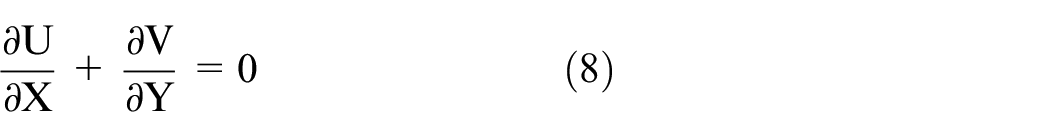
Continuity equation
Momentum equation
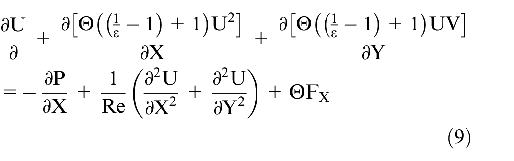
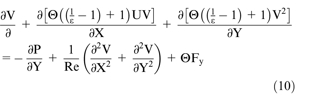
where

Energy equation

The dimensionless form often reveals the dimensionless parameters: the Reynolds number
Initial and boundary conditions
Initially, the fluid is motionless and the temperature inside the resonator is fixed at the ambient temperature
At the loudspeaker side, the velocity is expressed as follows 35

where
Here xB is the axial position of the boundary measured from the resonator closed end. So, at the loudspeaker side,

The temperature at x = 0 is written as 36

where Tm is the ambient temperature, PA is the pressure amplitude at the pressure antinode and ρ and Cp are the density and the specific heat at a constant pressure of the fluid, respectively. kw and ω are the wavenumber and the pulsation as defined above.
In the interfaces between the fluid region and the stack, the continuity of velocity and normal stress prevailing are adopted at the interfaces 37

where subscripts ‘int’, ‘fld’ and ‘prs’ refer to the interface layer, the fluid region and the porous region, respectively.
All the resonator solid walls are exposed to the ambient temperature and the no-slip boundary conditions are imposed
At x = L

At the horizontal sides of the resonator (y = 0 and y = H)

Numerical procedure
The numerical method adopted in this article is the LBM based on the Bhatnagar–Gross–Krook (BGK) approximation. 38 The LBM is a new and promising numerical method applied to fluid flow simulation. It is used in many research fields, including fluid flows in porous media, 39 oscillatory flow, 40 multiphase flow, 41 magneto-hydrodynamics 42 and fluid fluxes at the nano and microscopic scales. 43 Moreover, the LBM has proved that it is faster than the traditional computational fluid dynamics (CFD) methods. 44 The double distribution function (DDF) is used to discretize the flow and the heat transfer inside the computational domain. In fact, its mean principal is to define the temperature and the density flow fields using two distribution functions. The first distribution function named ‘f’ is used to simulate the density and velocity fields, which are the particle density distribution function. The second one is dedicated to the thermal field and it is named ‘g’. Furthermore, the LBM is based on four steps, 43 the collision step, the streaming step, the boundary conditions and the computing of macroscopic proprieties which are the density, the velocity and the temperature. 24 Besides, a two-dimensional lattice was been chosen with nine discrete speeds on a square grid of steps Δx = Δy = 1. The model is called D2Q9 and it is illustrated in Figure 2.
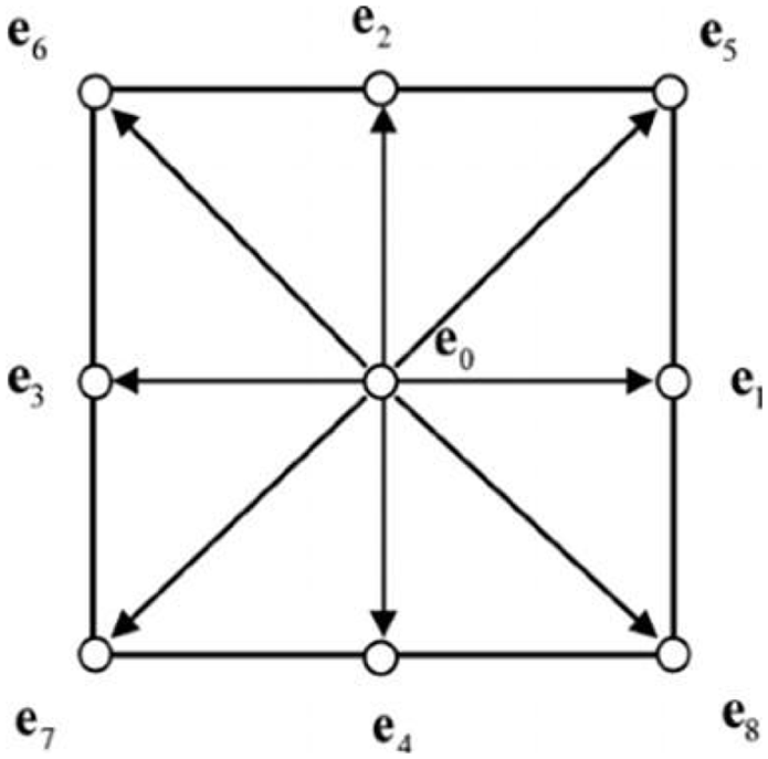
D2Q9 model.
The velocity field
In the LBM, for the D2Q9 model, the fluid velocity ‘u’ and the fluid density ‘ρ’ are calculated using the following equations. The system equation systems of fluid and porous media parts were combined.34,43 The binary parameter Θ defined in equation (1) has been used


where


where v(M, t) is a temporal velocity;26,34,45

where fi(M, t) is the density distribution function of particle located in the space position M(x, y) at the time step ‘t’.34,43
The determination of the density distribution function over time and within the calculation domain is effectuated by the collision step. The BGK approximation is used38,43

where


where ν is the kinetic viscosity of the fluid and


where
The next phase after the collision step is the streaming step 43

Temperature field
In the D2Q9 scheme, the temperature field (T(M, t)) in all the computational domain is given by equation (30). These equations are developed by combining the equations in a fluid region 43 and those related to the porous media section 34

where

where

where

where

where
where α is the fluid thermal diffusivity.
The streaming step is given as

Validation
The numerical code is developed using Fortran and is called porous media stack for a TAR (PMS-TAR). To validate the proposed model, two computing cases are considered. The former concerns a planar channel with a porous plug in the middle to test the efficiency of the LBM under this geometry. The fluid velocity vector is normal to the porous media interface plan. The simulation parameters are Pr = 0.71, Da = 10−2 and Re = 1. The presence of porous media inside the channel affects strongly the velocity profile in the centreline (Figure 3(a)). It can be concluded that using the developed code based on the LBM, obtained results are in concordance with previously published papers. 47

Comparison of our results and the published ones ((a) velocity centreline validation, (b) velocity profile validation inside the porous media for oscillating flow and (c) thermal profile validation inside the porous media for oscillating flow at t = Te/8).
The latter computing case is established to validate the velocity and the temperature profiles into a two-dimensional empty planar channel subject to oscillating flow. 27 The resolution parameters used in this simulation are the Reynolds number Re = 5, the Womersley number α = H/2(ω/ν)0.5 = 0.937, the angular frequency ω = 0.000785 and the wave amplitude A = 10−4. The velocity at t = Te/8 becomes developed and reaches a maximum value along the Y-axis (around 0.5) (Figure 3(b)). For the same position on the Y-axis, the dimensionless temperature falls to a minimum value as shown in Figure 3(c). Once again, obtained numerical results prove the validity of the approach and show the concordance between the PMS-TAR software outcomes and similar research papers.
Results and discussion
In this article, the LBM is applied to determine the dynamic and thermal fields inside the TAR (Figure 1(b)). The two-dimensional closed tube is derived from Tasnim and Fraser’s 36 geometry. The resonator dimensions are (H, 9.64H). The resonator is distributed as follows

where X1 and X2 are the stack end positions with X1 = (xc– lc/2)/H and X2 = (xc+ lc/2)/H; xc and lc are the stack centre position and the stack length, respectively. The oscillating flow is produced by the loudspeaker, which is located on the left side of the resonator (X = 0) and generates an acoustic wave whose velocity is sinusoidal. The emitted wave is reflected by the closed resonator end (x = L). Uniform temperature of 300°K prevails in the resonator and the stack. A frequency of 200 Hz is delivered by the loudspeaker. The Reynolds number and the Prandtl number are set to 25 and 0.71, respectively.
Dynamic field
In order to give a pictorial presentation of the flow inside the thermoacoustic resonator, the velocity field and U contours are recorded every quarter of period during the last simulation cycle. Figures 4(a)–(d), 5(a)–(c) and 6 illustrate the dynamic field in the three parts of the resonator. Figure 4 shows that the shape of the velocity profiles varies in the different parts. It can be depicted that the velocity reaches a maximum at the centreline of the geometry in the fluid parts (parts 1 and 3). Then, the motion of the fluid is accelerated in the first part and decelerated in the second one due to the presence of porous media and the closed end of the resonator. According to the same figure, the presence of annular effect can likewise be noticed at t = Te/4 and t = 3Te/4. The Richardson and Tyler 48 effect occurs near the top-bottom walls. This effect is as a result of both the wall viscous phenomenon and the fluid flow inertial force that comes back from the last period in the middle of the channel. 27
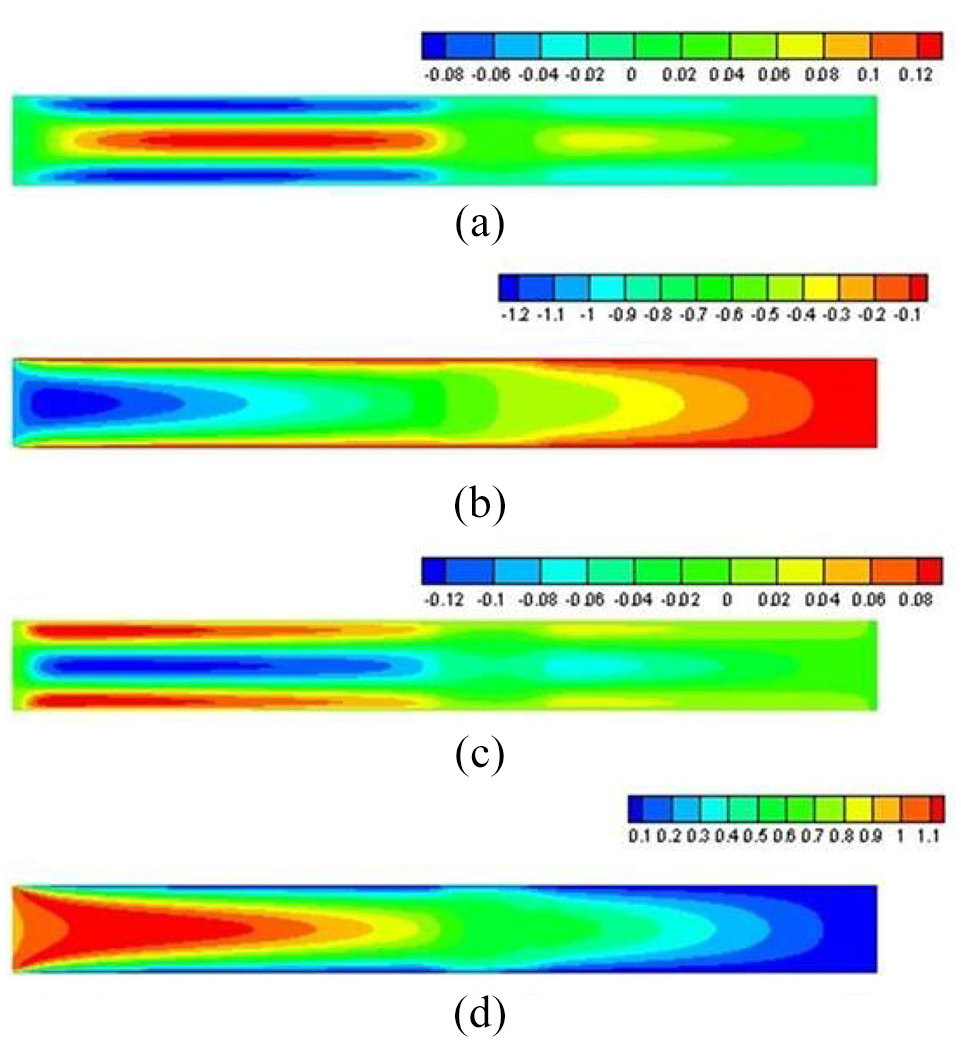
Instantaneous U contours in the resonator at four instants: (a) t = Te/4, (b) t = Te/2, (c) t = 3Te/4 and (d) t = Te.

Velocity fluctuation in a whole period at (a) X = 4.71, (b) X = 5.21 and (c) X = 7.57 for f = 200 Hz, Pr = 0.71, ε = 0.7, Da = 0.01, Rk = 30, Rc =2.5.
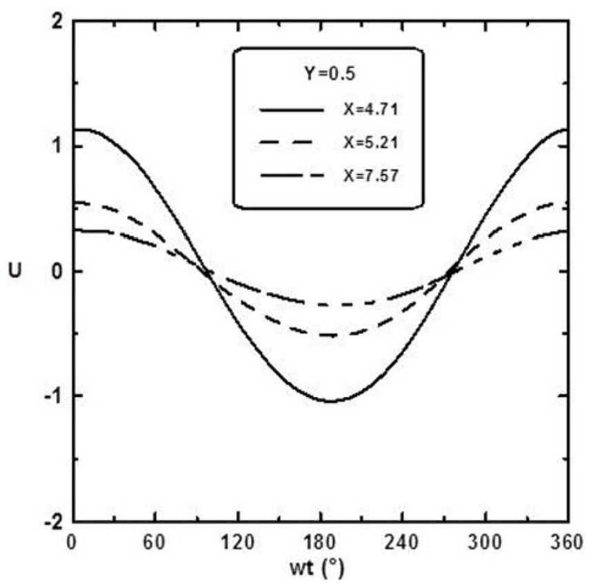
Periodically variation of U at Y = 0.5, X = 4.71, 5,21, 7.57 for xc = 5.21, f = 200 Hz, Pr = 0.71, ε = 0.7, Da = 0.01, Rk = 30, Rc = 2.5.
Figures 4 and 5(a) and (c) show that the maximum velocity is located in the channel centreline, within the fluid regions, parts 1 and 3, at t = Te/2 and Te. Then it decreases progressively to zero near the channel walls. However, at t = Te/4 and 3Te/4, the annular effect takes place. In part 2, the velocity profile is flattened, as shown in Figure 4(b). It is due to the presence of the solid matrix inside the porous media. The profile shows also an important dynamic boundary layer near the horizontal walls. 34
In the three parts of the resonator, a periodic symmetry is observed in the temporal velocity profiles throughout the resonator area with a phase difference of half a period (Figure 5). It is interesting to note that the amplitude of velocity decreases as the X-position becomes higher and gets away from the loudspeaker. In the porous stack, the dynamic boundary approaches the top-bottom walls more than it does in fluid regions.
Figure 6 shows the periodic variations of velocity at three different locations along the centreline of the channel. The velocity profile has the same trend in different instances. This velocity has two local maxima at wt = 0° and wt = 360° and a local minimum at wt = 180°. Therefore, the amplitude of the velocity decreases gradually from the inlet to the resonator exit. The observed decrease can be explained by the presence of the porous media and the closed end of the resonator. 27
Figure 7 demonstrates the effect of Darcy number on the velocity in the middle of the stack. It is clear that the presence of a porous medium affects deeply the flow. The amplitude of the velocity is proportional to the Darcy number as long as it has low values. In this case, the use of material with high permeability is recommended, to enhance the flow in the porous stack.

Dimensionless velocity profiles at the middle of the stack at different values of the Darcy number for ε = 0.92, Rk = 10, Rc = 2.5 and Ec = 0.1.
Thermal field
The main focus of this section is to study the effect of different stack parameters and to specify the best combination for a TAR having a squared stack made of porous media. The performance of the TAR is evaluated using the average temperature difference between the stack extremities across a period at a steady state. It is calculated as follows (equation (37))

where

Te is the time period of the wave, Tf is the simulation time, Tm(x) is the average of the temperature at the ‘x’ section, H is the width of channel, x = n1 and x = n2 are the stack extremities, and T(x, y) is the temperature in the (x, y) position.
In the present section, the effect of the system parameters is studied. Special attention is paid to the viscous dissipation term since it is often neglected in previous researches.
The effect of the Darcy number on the TAR performance is examined and presented in Figure 8. The lower is the value of the Darcy number, the larger the indicator is. This indicator is the performance called the time-averaged temperature difference

Time-averaged temperature difference between the stacks extremities for different Darcy numbers for Rc = 2.5, Rk = 10, Ec = 0.1, ε = 0.7, xc = 5.21 and ls = 1.
Figures 9–12 show the time-averaged temperature difference generated across the stack, over a cycle,

Dependence of the time-averaged temperature difference between the stacks extremities on the Eckert number for different Darcy numbers for Rc = 2.5, Rk = 10, ε = 0.7, xc = 5 and ls = 1.

Dependence of the time-averaged temperature difference between the stack extremities on the Eckert number for different heat capacity ratio for Da = 0.001, Rk = 10, = 0.7, xc = 5.33 and ls = 1.

Dependence of the time-averaged temperature difference between the stacks extremities on the Eckert number for different stack porosities Da = 0.001, Rk = 10, Rc = 20, xc = 5 and ls = 1.

Dependence of the time-averaged temperature difference between the stacks extremities on the Eckert number for different heat conductivity ratio for Da = 0.001, ε = 0.3, Rc = 20, Ec = 0.2, xc = 5 and ls = 1.
Figure 10 shows the dependence of the
Figure 11 illustrates
Figure 13 presents the temperature difference across the stack versus the stack centre positions varying from λ/16 to 3λ/16. The existence of a critical value of stack position is noticed, for which the considered system is more efficient. Therefore, the maximum temperature difference observed is 67.5°C at xc =λ/8. This position coincides with the middle of the resonator and the velocity antinode. 51

Time-averaged temperature difference generated across the stack extremities versus stack centre positions for Da = 0.001, Rc = 20, Rk = 1, xc = 5.33 and ls = 1.
Conclusion
A numerical investigation is performed to analyse the impacts of some parameters on the efficiency of a solar-powered TAR. The studied TAR is equipped with a rectangular section resonator and a homogeneous porous media stack. The considered parameters include the Darcy number, the stack porosity, the heat capacity ratio, the heat conductivity ratio, the Eckert number and the stack centre position. The Darcy–Brinkmann–Forchheimer extended model is employed for the momentum equation. The proposed approach follows the LBM using the BGK approximation. The time-averaged temperature difference between the stack ends over a cycle is used as an indicator to qualify the TAR performance. The used model consists of solving the Navier–Stokes and the ideal gas equations. The velocity and temperature fields are obtained and analysed. The results obtained in this article are as follows:
The flow is accelerated in the first part and decelerated in the second one due to the presence of porous media and the closed end of the resonator. The velocity profiles are harmonic and present a phase angle for half a period.
The amplitude of velocity decreases getting away from the loudspeaker. The dynamic boundary approaches the top-bottom walls in the porous stack; more than it does in fluid regions.
The flow in the considered system is enormously affected by the Darcy number.
The use of porous material with low permeability and high conductivity in the TAR enhances its efficiency.
The viscous dissipation effect, considered internal source, affects the performance of the system. This impact becomes important using a porous material with higher values of the heat capacity ratio.
The best stack centre location is the middle of the quarter wavelength resonator.
Footnotes
Handling Editor: James Baldwin
Declaration of conflicting interests
The author(s) declared no potential conflicts of interest with respect to the research, authorship and/or publication of this article.
Funding
The author(s) received no financial support for the research, authorship and/or publication of this article.