
Abstract
This paper established a lateral stiffness coupling model to investigate the lateral characteristics of air spring system under crosswind conditions. The nonlinear super-elastic characteristics, coupling characteristics of the air spring, lateral stiffness characteristics of emergency spring, and damping force are studied. The accuracy of the lateral stiffness model is validated by comparing with experimental data. In addition, the impact of geometric parameters on the lateral stiffness characteristics is discussed by a sensitivity analysis method, as well as the effect of the lateral stiffness model on vehicle mechanical performance is analyzed. The conclusions show that the lateral stiffness model can well predict the lateral characteristics of the air spring system, and provide theoretical guidance for the parameter design of rail vehicles and vehicle ride comfort improvement.
Introduction
With the increase in the vehicle speed and the lightweight of vehicle design, the risk of vehicle derailment or rollover under the influence of crosswind has become a non-negligible problem. 1 Air spring system is an important anti-rollover device of the secondary suspension system, which can improve the anti-rollover ability in the presence of crosswind, reduce the lateral sway of the car-body relative to the bogie, and mitigate wheel unloading. 2 The air spring system is located between the car-body and bogie, as shown in Figure 1.
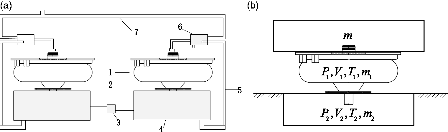
Structure of the secondary suspension system (a) and air spring system (b).
When railway vehicles encounter strong crosswind or curve, a harmful lateral vibration and car-body-swaying phenomenon will occur. 3 The lateral stiffness and damping characteristics of air springs can effectively attenuate the harmful vibrations and provide better ride comfort of railway vehicles. Therefore, the lateral stiffness and damping characteristics of air spring system are the focus of this article.
Numerous scholars have conducted extensive research, and many achievements have been made toward developing a more detailed and precise model of air spring system. Chen et al. 4 proposed a horizontal stiffness of air spring, which was composed of the horizontal stiffness of rubber bellows and rubber spring, and the relationship between the horizontal stiffness of rubber bellows and rubber spring and various influencing factors was analyzed. Facchinetti et al. 5 developed a quasi-static model and a dynamic model for air spring suspension by using a full-scale test rig. The coupling between shear and roll stiffness was included in the quasi-static model, the dependency of lateral/roll stiffness parameters on the load was incorporated in the dynamic model, and the coupling behaviors between lateral and roll deformations of air spring suspension were investigated. Thomas et al. 6 investigated the responses of a stationary rail vehicle to lateral car-body excitations imitating a crosswind by means of a full-scale measurements, and the influence of the lateral stiffness, roll stiffness, and air spring friction on the vehicle response to a crosswind were studied. Liu et al. 7 established a nonlinear finite element lateral stiffness model with considering material nonlinearity, geometric nonlinearity, and contact nonlinearity. Qi et al.8,9 constructed a horizontal stiffness calculation model of air spring based on the nonlinear finite element method, and the characters of rubber, ply disposition, fluid–solid coupling, and contact of top plate apron were considered. Berg 10 proposed a nonlinear air spring model for general three-dimensional motions, and the nonlinearity of the rubber friction and air flow in the pipe is considered. Li et al. 11 established a uniform physical model of an air spring based on thermodynamics and hydrodynamics. Docquier et al.12,13 obtained a complete air spring model with a pneumatic circuit based on thermodynamics. Zhu et al.14,15 developed an air spring dynamic model by considering the thermodynamics of the bellow-pipe-tank pneumatic system, the effective friction, and viscoelastic damping of the bellow rubber.
Throughout the above research literature works, the stiffness modeling methods of air spring system are mainly divided into mechanical analysis method, experimental method, thermodynamic method, and finite element method. Although the stiffness modeling method of air spring has matured, the research on the lateral stiffness coupling modeling is rare. Under a combined effect of track excitation and crosswind, a coupling deformation of lateral displacement and rolling motion of air spring occurs. Therefore, this article presents a lateral stiffness coupling model of air spring system, the nonlinear super-elastic characteristics, coupling characteristics of air spring, lateral stiffness characteristics of emergency spring, and damping force of air spring are taken into account.
The layout of this article is as follows: in section “Vehicle–crosswind interaction model,” an interaction model of vehicle under an influence of crosswind is established, and a lateral stiffness model is proposed which consists of nonlinear super-elastic characteristics, coupling characteristics, lateral stiffness of emergency spring, and damping force of air spring. In section “Experiments,” a full-scale laboratory air spring test bench (ASTB) is introduced, and a full set of experimental results is available to allow comparisons between simulation and experimental data. In section “Parameter identification and model validation,” the model parameters are identified through a numerical fitting method, and a comparison between the simulation results of the proposed lateral stiffness model and the experimental data is performed to verify the accuracy of the proposed lateral stiffness model. In section “Parameter analysis and discussion,” the relationship between the lateral stiffness characteristics and the geometric parameters such as effective area, equivalent volume, lateral displacement, roll angle, and excitation frequency is analyzed in terms of the proposed model, as well as the impact of the proposed lateral stiffness model on the vehicle ride comfort is discussed.
Vehicle–crosswind interaction model
In this section, the vehicle–crosswind model is performed to depict the interaction between the characteristics of air spring system and the crosswind aerodynamic force.
Simulation of crosswind
Crosswind is a typical scenario of railway infrastructure, which equipped with randomness, spatial correlation, and time-varying characteristics. The influence of crosswind on the dynamics of rail vehicles has been considered in previous studies. In this article, the focus is on the lateral aerodynamic force of crosswind acting on the vehicle car-body, the lateral aerodynamic force

Coupling model of air spring and vehicle
Figure 2 exhibits a vibration diagram of rail vehicle running on a straight track in the presence of crosswind, a coupling deformation of lateral displacement, and rolling movement of air spring occurs, as shown in Figure 2(b). The coupling deformation of air spring with its unique stiffness and damping characteristics effectively attenuates vehicle vibration, ensures the running quality of vehicles. The stiffness and damping generated by air inflation or exhaust from the air spring system generate the corresponding vertical, lateral responsive force, and roll torque, which are denoted by
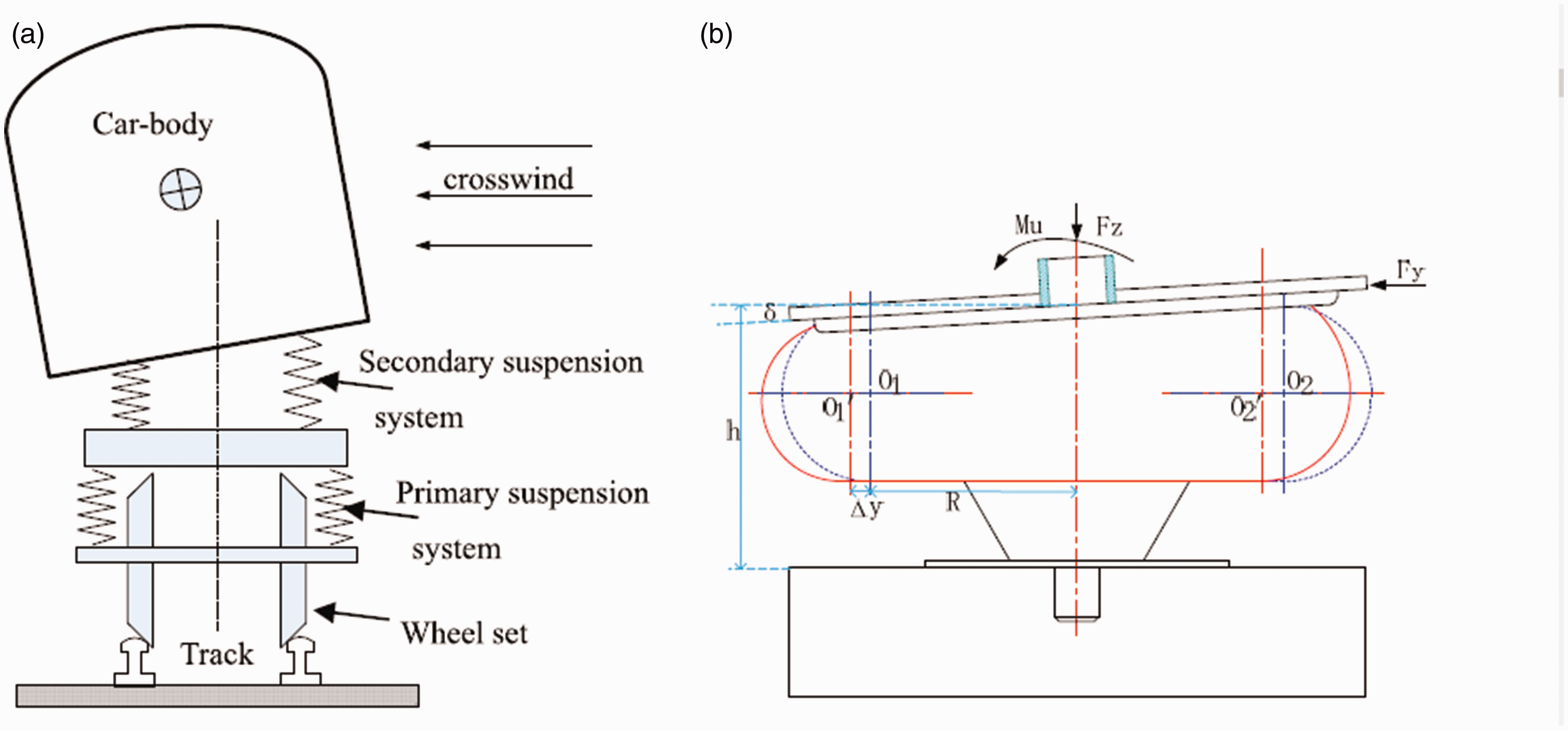
Rear-view of vehicle running on a straight track subject to crosswind (a) and coupling deformation of air spring (b).
According to Figure 2(b), a nonlinear lateral stiffness coupling model of the air spring system is constructed, as shown in Figure 3. The lateral dynamic stiffness

Nonlinear lateral stiffness model of air spring system.
Nonlinear elastic stiffness of rubber diaphragm
The lateral stiffness characteristics of air spring are mainly affected by internal pressure and variable geometric parameters. Referring to literature works,12,14,15 the inertia of air mass in air spring rubber diaphragm can be ignored in this nonlinear stiffness model, and the change process of the internal pressure is considered as an isentropic process.
The mass flow rate in the rubber diaphragm can be expressed by a continuity equation

The variation of pressure and mass in the rubber diaphragm can be expressed by the polytropic equations

The temperature inside the diaphragm can be calculated through a perfect gas equation

The rubber diaphragm volume

The change rate of the diaphragm volume

Given the effective area is a nonlinear function can be expressed as

Differentiating equation (6) and combining equation (3) yield the time variation of the diaphragm internal pressure

According to the pressure gradient
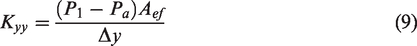
Substituting equations (7) and (8) into equation (9), the lateral stiffness of rubber diaphragm can be written as

Equivalent torsional stiffness model
According to the previous studies,5,19 the vertical behavior of air spring suspension decoupled from lateral/roll components. That is the vertical force generated by the air spring is not affected by the lateral or roll deformation, and there is a non-negligible coupling effect between the lateral deformation and the roll deformation in the lateral direction. In terms of Newton’s law, the lateral reaction force and the roll torque of air spring can be expressed as follows

According to Miguel et al.,
20
the equivalent stiffness is based on the contribution of the torsional stiffness of air spring. The torsional stiffness of the rubber diaphragm

Emergency spring stiffness model
The emergency spring and air spring are always designed in series superposition. Therefore, the lateral aerodynamic force of crosswind acting on vehicle car-body is undertaken by the air spring and the emergency spring in parallel. The lateral stiffness of emergency spring is defined as

Damping coefficient
The damping force mainly comes from the damping generated by air mass moving through the orifice and damping force produced by bellow rubber viscoelasticity.21,22 This article focuses on the former. The reason is that the air flows through the orifice with a fast speed and has a small contact area with pipe wall; the temperature in the air spring has no heat exchange with surrounding environment, so the air change process can be considered as an adiabatic process.9,14 The air mass flow through the orifice can be expressed as follows
23

where
In the vicinity of an equilibrium point, the nonlinear air mass flow equation

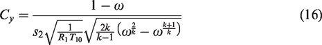
It can be seen that the damping coefficient is closely related to the orifice diameter and the pressure ratio of air spring.
Lateral stiffness model and damping coefficient
Figure 3 shows the proposed lateral dynamic stiffness model which consists of three elements in parallel: the stiffness of rubber diaphragm

The rubber diaphragm responsive force


The damping force

The emergency spring responsive force

Therefore, under the effect of lateral aerodynamic force of crosswind, the lateral dynamic stiffness

Experiments
In this section, a full-scale laboratory test bench is introduced to verify the proposed nonlinear dynamic stiffness model, and the structure of the ASTB, test conditions, and experimental results are performed in detail.
ASTB
In previous studies, the air spring system was tested on a full-scale ASTB;5,24 hence, a full set of experimental data is available to allow comparisons between simulation and experimental results. Referring to literature,5,24 the structure schematic of the ASTB is shown in Figure 4(a).

Full-scale schematic of ASTB (a), and schematic of pneumatic circuit and location of pressure sensors (b).
A rigid bolster was mounted over two air springs, and three hydraulic actuators were connected to the bolster: two of them were mounted in the vertical direction over each air spring to apply vertical loads, and the final one was arranged in the lateral direction representing a lateral aerodynamic force of the crosswind. A vibration platform was mounted under the bogie frame to simulate track irregularity excitation, which equipped with six load cells to measure the vertical and lateral force components and moments. Three internal transducers of the actuator were adapted to measure the vertical force, lateral force, and roll torque of the air spring. Laser displacement transducers were mounted below the bolster to measure the vertical displacement, and an accelerometer was also mounted at the center of the bolster, measuring the lateral acceleration.
Pneumatic system
Figure 4(b) shows a detailed representation of the pneumatic circuit of the air spring system, which consists of two air springs, two auxiliary chambers, two leveling valves, and a differential pressure valve. In addition, pressure sensors were installed in different places to monitor the pressure change of the pneumatic system.
Experimental tests
Under the combined action of lateral aerodynamics force of crosswind and track excitation, the dynamic tests of the lateral stiffness of the air spring system were carried out. A full set of experimental results was obtained, which can reflect the lateral stiffness and damping characteristics of the air spring system.
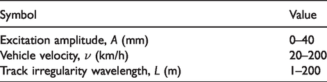
Test bench input parameters
With the intention of experimental conditions close to the ones experienced during service by the air spring suspension system, the air spring preload is defined. The vertical preload on each air spring changes from 53.5 to 145 kN, indicating the empty load AW0 and heavy load AW3. A rolling motion of air spring will be introduced by applying asynchronous vertical preload on each air spring. The main parameters for the ASTB are summarized in Table 1.
Main parameters of the air spring test bench.

Track excitation input
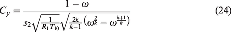
In this article, a unilateral cosine wave is used to simulate the track excitation, which is mainly affected by the vehicle speed and vibration frequency. It can be expressed as follows


Track irregularity excitation parameters.

Characteristics of excitation displacement: (a) displacement versus amplitude; (b) displacement versus angular frequency.
As shown in Figure 5(a), the displacement is linearly related to the excitation amplitude, which increases with the increase in the amplitude. The harmonic angular frequency
Experimental results
Under the combined action of crosswind and track excitation, the relationship between the lateral stiffness and damping of the air spring and the internal pressure is shown in Figure 6.

Experimental results: (a) lateral stiffness versus pressure (AW0), (b) lateral stiffness versus pressure (AW3), and (c) damping coefficient versus pressure.
The lateral stiffness of air spring increases with the increase in the internal pressure, and decreases with the increase in the excitation amplitude, as shown in Figure 6(a) and (b). Furthermore, with the increase in the pressure ratio of air spring, the damping coefficient first increases and then decreases, and decreases with the increase in the orifice diameter, as shown in Figure 6(c). Therefore, too large and too small pressure ratio and orifice diameter are not conducive to the damping characteristics of the air spring.
Parameter identification and model validation
Equation (23) shows the input parameters have an important influence on the accuracy of nonlinear lateral stiffness model. In this section, the undefined parameters
Parameters identification
The lateral stiffness characteristics are closely related to the variable geometric parameters, such as the effective area
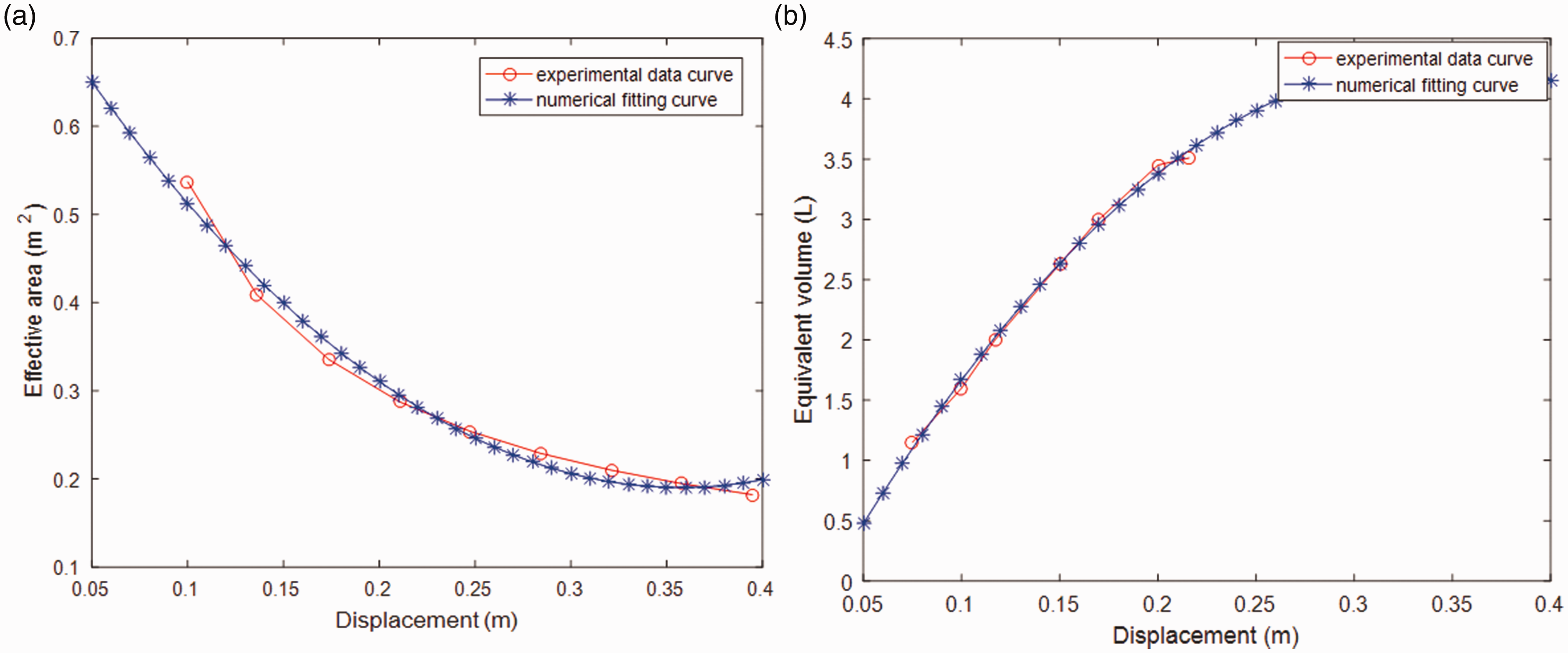
Change curves of effective area and equivalent volume: (a) effective area curves and (b) equivalent volume curves.
The curves in Figure 7 show that with the increase in the lateral displacement, the effective area decreases, and the equivalent volume increases nonlinearly. Comparing Figure 7(a) and (b) shows that the change rate of the effective area is obviously smaller than that of the equivalent volume. The other geometric parameters used for the lateral stiffness model simulation are listed in Table 3.
Main parameters for the simulation model.

Model validation
In this section, the simulation results of the proposed lateral stiffness model are compared with the experimental data from the ASTB, and the comparison results are shown in Figure 8.

Comparison results: (a) lateral stiffness comparison results (AW0), (b) lateral stiffness comparison results (AW3), and (c) damping coefficient comparison results.
As can be seen from Figure 8(a) and (b), the simulation result of the proposed model is consistent with the experimental data. The lateral stiffness of the air spring increases as the internal pressure increases, and the stiffness value in the case of AW3 is larger than that of AW0, which indicates that the lateral dynamic stiffness increases with the increase in the sprung load. Furthermore, the simulation result of the damping coefficient of the proposed model is in good agreement with the experimental data, but there is a deviation about 5% between them, the reason for this behavior is that the proposed model only considers the damping produced by the orifice, and the damping contributed from the bellow rubber viscoelasticity is not considered. In a word, the proposed lateral stiffness model can well characterize the lateral behaviors of the air spring system.
Parameter analysis and discussion
Through the above model validation, the accuracy of the proposed lateral stiffness model is validated. In terms of the proposed lateral stiffness model, the relationship between the lateral performances and geometric parameters is analyzed and discussed by a sensitivity analysis method in this section.
Lateral displacement dependence
The lateral displacement of the air spring not only affects the geometric parameter of the rubber diaphragm but also the lateral stiffness characteristics of the air spring system. The relationship between the lateral stiffness and lateral displacement under different load cases is shown in Figure 9.
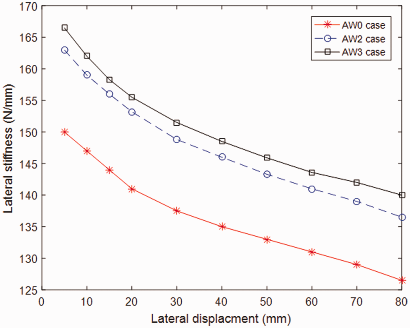
Lateral stiffness versus lateral displacement.
The simulation results show that the lateral stiffness decreases with the increase in the lateral displacement, and increases with the increase in the sprung load. The reason is that with the increase in the lateral displacement, the change rate of the equivalent volume is larger than that of the effective area, resulting in the decrease in the lateral stiffness, as shown in Figure 7. Therefore, in order to prevent excessive lateral displacement of car-body, and improve vehicle stability and ride comfort, an air spring is usually matched with a lateral damper. 25
Roll angle dependence
When vehicle running in the presence of crosswind, a car-body swaying phenomenon and a rolling movement will occur. The roll angle directly influenced the stiffness characteristics of the air spring. The relationships of the lateral stiffness and roll angle under the conditions of AW0 and AW3 are shown in Figure 10.
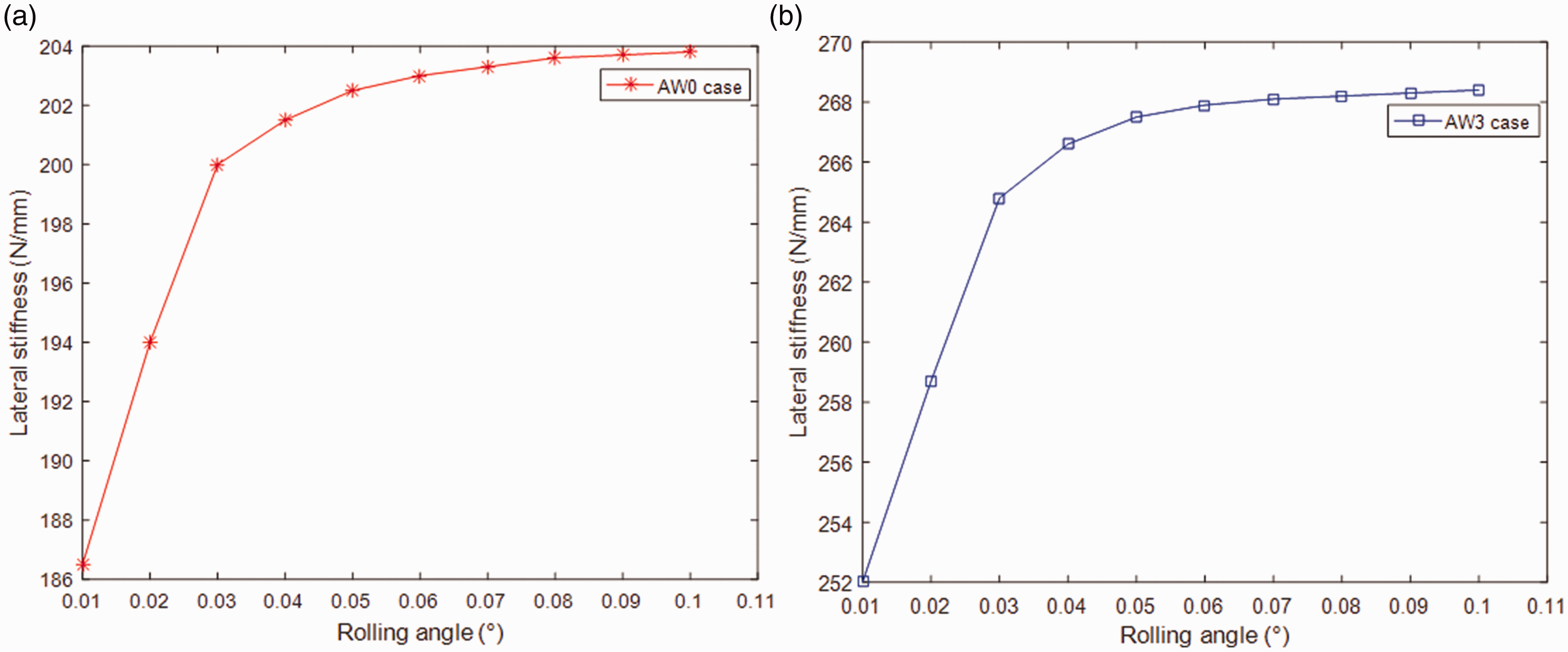
Lateral stiffness versus rolling angle: (a) AW0 case and (b) AW3 case.
Under the cases of AW0 and AW3, the lateral stiffness of the air spring increases sharply with the increase in the roll angle. When the roll angle exceeds 0.05, the lateral stiffness of the air spring changes slightly. This is because a large lateral force on the car-body induces a large roll angle and lateral displacement, and then the air spring can alleviate the lateral vibration of the car-body by adjusting its stiffness. In addition, the railway vehicles are usually equipped with anti-roll bars to prevent the car-body from rolling motion. 6
Frequency dependence
Excitation frequency is a major factor affecting the lateral stiffness and damping characteristics of air springs. When the track excitation amplitude is 5 mm, the relationship between the lateral stiffness and damping of air spring and excitation frequency under different load conditions are shown in Figure 11. The lateral stiffness increases with the increase in the excitation frequency, and at high frequency, the stiffness oscillates and slowly converges to a stable state, as shown in Figure 11(a) and (b). Figure 11(c) shows the damping coefficient has a maximum value at the natural frequency and a smaller value at the high vibration frequency. According to Figure 11, the air spring is used as a damper in the low-frequency range and as a spring in the high-frequency range.

Lateral stiffness and damping versus frequency: (a) lateral stiffness curve (AW0), (b) lateral stiffness (AW3), and (c) damping coefficient curve.
Effect of air spring lateral stiffness model on vehicle ride comfort
The merits of the proposed lateral stiffness model on the improvement of vehicle mechanical performance can be quantitatively evaluated by vehicle ride comfort index. In this article, the CEN standard ENV 12299 is used to evaluate the influence of the proposed lateral stiffness model on vehicle ride comfort.
Vehicle vibration response
According to the above discussion, the dynamic lateral stiffness and damping coefficient of the air spring system are introduced into the numerical calculation of vehicle vibration. The vehicle speed is set to be 100 km/h, the vertical sprung load is 53.7 and 145 kN, and the track excitation amplitude is 5 mm. Based on Figures 1(b) and 2, the mechanical schematic diagram of the car-body vibration under the combined action of track excitation and crosswind is shown in Figure 12.

Mechanical schematic diagram of car-body vibration.
The equilibrium equation of the car-body in the present of crosswind can be described as follows

Substituting the lateral response force 
According to the vibration equations (23) and (28), the lateral acceleration magnitude of the car-body under the load of AW0 and AW3 can be obtained.
Assessment index selection
The acceleration magnitude of car-body is closely related to the vehicle vibration and ride comfort. According to the car-body lateral accelerations, the CEN standard ENV 12299 is used to evaluate the ride comfort index.
26
Under various crosswind speeds and vertical sprung load AW0 and AW3, the angular frequency
Acceleration of car-body and ride comfort index.

The simulation results of the acceleration and ride comfort index show that with the increase in the wind speed, the car-body lateral acceleration and the ride comfort are gradually increased, and the ride comfort is within the range of comfortable. It is also found that the increment of the vertical sprung load can reduce the lateral acceleration and improve the vehicle ride comfort.
Conclusion
In this study, the lateral characteristics of air spring system in the presence of crosswind is investigated by establishing a lateral stiffness model and a damping model. The lateral model consists of three elements in parallel: the stiffness of rubber diaphragm, the stiffness of emergency spring, and the damping coefficient, in which the nonlinear super-elastic characteristics, coupling characteristics of air spring, lateral stiffness characteristics of emergency spring, and damping force of air spring are considered. The lateral stiffness and torsional stiffness of air spring rubber diaphragm, as well as the damping coefficient of air spring, are derived on the basis of thermodynamics, hydrodynamics, and Newton’s law. In order to validate the accuracy of the proposed lateral stiffness model, the proposed model was compared with the experimental data from ASTB. Furthermore, the influence of the lateral displacement, roll angle, and excitation frequency on the lateral performances is discussed in terms of the proposed model, as well as the effect of the proposed lateral stiffness model on vehicle mechanical performance is analyzed. The conclusion shows that the lateral stiffness model can well characterize the lateral characteristics of the air spring system, and provide theoretical guidance for the suspension design of rail vehicles and the improvement of vehicle mechanical properties.
Footnotes
Handling Editor: James Baldwin
Declaration of conflicting interests
The author(s) declared no potential conflicts of interest with respect to the research, authorship, and/or publication of this article.
Funding
The author(s) received no financial support for the research, authorship, and/or publication of this article.