
Abstract
Micro-cantilever has shown wide application prospect in the field of micro-sensors, actuators, gyroscope, and so on. There are abundant research studies on simple cantilever beam models, but there are few on S-shaped folding cantilever with complex structure, although it is widely used. In order to study the deformation failure of S-shaped folding cantilever, the force analysis of S-shaped folding cantilever was carried out in this article, and the stress values of different positions under the external load of the cantilever were deduced. The finite element model about S-shaped folding cantilever was built based on software ANSYS. The theoretical calculation was compared with the finite element calculation, and the results showed that the max stress is 681 MPa based on the derived theoretical formula, the max stress is 673 MPa based on the ANSYS, the error is 1.18%, which can prove formula is accurate. To further validate the stress predicted by the mathematical modeling, a micro-force testing platform was built to test the cantilever. Since the stress value cannot be measured directly in the test, the force corresponding to the stress was taken as standard and compared it with the simulation. The tested external force was corresponding the yield limit. The results showed that the experimental force was 0.06462 N before the plastic deformation occurred, the theoretical outcome was 0.065231 N corresponding the yield limit, the error was 0.94%. Both simulation and experimental results depict that the theoretical model is effective for predicting the stress of the S-shaped folded cantilever. The theoretical model helps to enhance the efficiency, and improve the performance, predictability, and control of the S-shaped folding cantilever.
Introduction
Limited by space size and drive energy, most of microelectromechanical system (MEMS) devices usually integrated many function into one, such as energy transfer, movement conversion, and actuation. 1 Most designers use micro-elastic-cantilever to achieve this kind of multifunctional mechanism, so the micro-cantilever is a kind of typical and important MEMS device. It is also essential to micro-sensor, micro-actuator, and micro-gyroscope, which can not only provide elastic force, but also transfer energy.2–6 The performance of micro-cantilever plays an important role in whether the device can work according to the design requirements. In Camilo 7 and Charles, 8 L-shaped, W-shaped, and S-shaped folding cantilevers are mentioned, respectively (see Figure 1 below), which is important to MEMS actuator.

The complex-shaped cantilever.
Among all kinds of planar-shaped folding cantilevers, S-shaped cantilever is widely used because of its simple structure and the rounded corner is less prone to stress concentration. Compared with other special-shaped cantilever beam structures, the S-shaped folding micro-cantilever has smaller stiffness and is able to obtain large deformation, so S-shaped folding cantilever is widely used in some actuators requiring greater deformation. At present, there have been many studies on the performance of S-shaped folding cantilever. Li and Shi 9 and Guang and Shi 10 studied the calculation formula of the stiffness of S-shaped micro-cantilever beam. In Liu and Hao 11 and Nie et al., 12 the stiffness of S-shaped micro-cantilever was simulated and tested. The research studies of existing S-shaped micro-cantilever performance mainly aimed to its stiffness research, but sometimes although stiffness is met, the problem of failure due to excessive deformation is still difficult to solve, the research about S-shaped folding cantilever is still inadequate.
The author found that the maximum deformation of S-shaped folding micro-cantilever always appeared at the rounded corner when the external load is too large in the experiment. It can be seen that in addition to stiffness, the stress is equally important. The stress directly affects the failure of the device and the maximum load that the cantilever can bear.
This article researched the load distribution of S-shaped cantilever, obtained the characteristics of load distribution, and the calculation formula of stress was deduced. The stress formula will provide certain basis for the failure study of cantilever beam.
Mechanical model of S-shaped folding cantilever
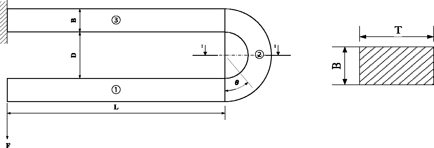
The S-shaped folding cantilever is composed of N elements (shown in Figure 1), each element has the same shape and size (shown in Figure 2). Take one of the elements and build its mechanical model, the element is divided into 3 parts, part ①, part ②, and part ③, as shown in Figure 3. B and T are, respectively, the section width and thickness of folded cantilever, L is the length of folded cantilever, and D is the gap.

Model of S-shaped folding cantilever.
One element of S-shaped folding cantilever.
One end of the cantilever is fixed, and the other end is applied to a downward force. There is only the bending moment, so the cantilever is simply bending deformation.
In area ①, the bending moment is
In area ②, the bending moment is
In area ③, the bending moment is
As can be seen from the above loading formula, the bending moment M in area ① increases with the increase in x. When x = L, the bending moment reaches the maximum and the value is FL. In area ②, the bending moment M increases with the increase in θ when θ is less than 90°. When θ is 90°, the bending moment reaches the maximum and then the bending moment M decreases with the increase in θ. When the θ is 180°, the bending moment M is minimum, the value is −FL, the bending moment is the same when θ is 0° and 180°. In area ③, the bending moment M decreases with the increase in x, the bending moment decreases to 0 when it is in anchor.
It can be seen from the above analysis, the bending moment distribution in area ② is axisymmetric and the maximum bending moment is in the in symmetrical section. Every element is under the same bending moment, so when the S-shaped folding cantilever is under an external force, the maximum stress is always in I–I section of the corner.
Theoretical model of the stress distribution
Derivation of stress formula
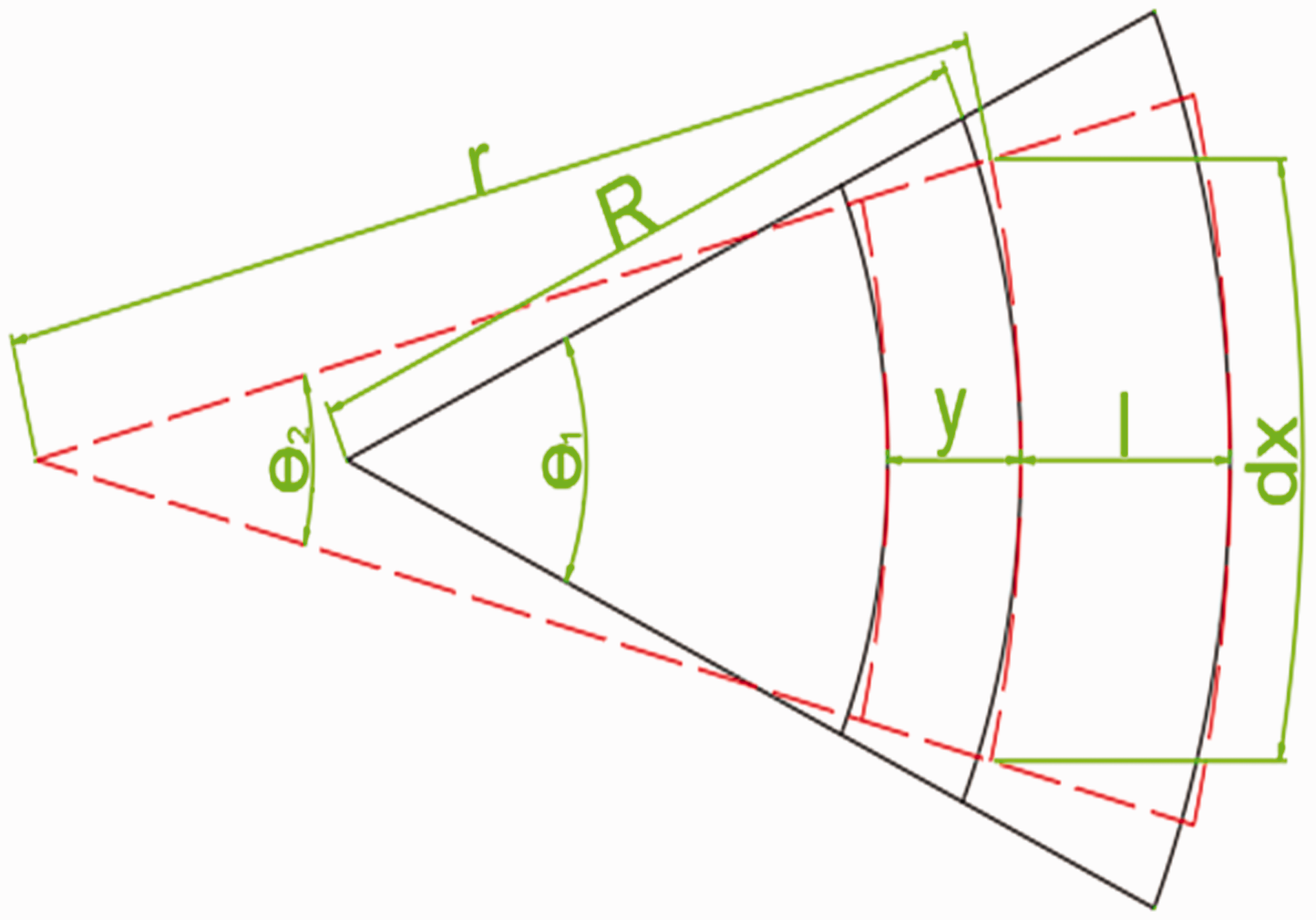
In Figure 4 above, R is radius of neutral surface before deformation, r is radius of neutral surface after deformation, y is the distance from neutral surface, l is the distance that from excircle to neutral surface, dx is the length of micro-arc. The stress–strain relationship within the linear elastic range follows

Undeformed and deform diagram of area ② under the external force.
The deformation of the plane y away from neutral surface is

From formula (2), the strain of the plane y away from neutral surface is

The cantilever is deformed by pure bending, so from the relation between force and transmogrification

Combining formulas (1), (3), and (4), we can obtain

From geometrical relationship

Combining formulas (5) and (6), we can obtain

From the relation between force and transmogrification

Combining the formulas above

In formula (9)

From formula (9), r is related to the external moment of force, and both of R, y just depend on the cantilever’s structural parameters.
Finite element model
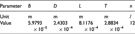
The material properties and geometric parameters of the S-shaped folding cantilever are shown in Table 1. The cantilever is modeled in ANSYS, the deformation of the cantilever is assumed to be within its elastic range. The cantilever is fixed at one end, and the other end is loaded to 0.1-N force. The stress distribution is shown in Figure 5.
Material and geometrical parameters of cantilever.


Stress distribution of cantilever.
From Figure 5, each element of the S-shaped folding cantilever has the same stress distribution, and the stress distribution is symmetric along the x-axis. The stress value located on the x-axis is the minimum, and then the stress value gradually increases along the y direction. The maximum stress occurs on the surface of the inner semicircle at the bend. The simulation results are consistent with the theoretical analysis.
In order to reduce the accumulation of errors, the bend of the beam is modeled and loaded separately. And the stress distribution is calculated in ANSYS. The force of 0.1 N can be equivalent to the bending moment load of 9.37e-5 N m, the bending moment is loaded to the cantilever, and the stress distribution is shown in Figure 6.

Stress distribution of cantilever’s bend.
According to Figure 6, the neutral axis of the section is close to the inner cylinder, not at the center of the form, and the maximum stress value is 6.81 × 10⁸ Pa.
The stress value at the 90° section of the folded cantilever beam bend is calculated by formula (9), and the data are shown in Table 2.
Theoretical calculation result.

From the theoretical calculation, the neutral axis of the section is located at the position 4.66e-5 m away from the inner circle surface, closer to the inner circle surface, and not at the centroid, which is consistent with the simulation results. The maximum stress value calculated theoretically is 6.73 × 10⁸ Pa, and the finite element simulation result is 6.81 × 10⁸ Pa, with an error of 1.18%. It can be proved that formula (9) is accurate.
Experiment
Due to the limited condition in my laboratory, the stress cannot be directly measured, and can only be obtained indirectly by measuring the force. From the known yield limit
Take sample 1 as the test object (as shown in Figure 7 below), and the geometrical parameters of sample 1 are showed in Table 3. Then, conduct tensile test on sample 1, the force and displacement (deformation) are tested by tensile test. The test device is built by the author himself (Figures 8 and 9). Test equipment include X, Y direction electric micro-displacement platform; X, Y, Z direction manual micro-displacement platform; clamping rod; double parallel beam force transducer; the charge-coupled device (CCD) camera; ring light source; quartz glass plate with high light transmission; X direction laser displacement sensor; Y direction laser displacement sensor; three-axis micro-controller; dual channel laser displacement sensor controller; image acquisition card; and master computer. The CCD camera is located directly above the S-shaped folding cantilever beam and arranged along the z-axis. The annular light source is illuminated along the negative direction of Z to form a clear image. The image acquired by the CCD camera is transmitted to the computer by the image acquisition card. The computer controls the movement of the electric micro-displacement platform 1 in the X direction and the electric micro-displacement platform 2 in the Y direction through the displacement platform controller.

SEM picture of sample 1.
Geometrical parameters of sample 1.

Testing device sketch.

Photo of testing device.
The testing process is imaging by opening the CCD camera and a light source, the image is transmitted to the computer through acquisition card, the computer discriminates image resolution and then controls the three-axis micro-controller. Adjusting the X, Y, and Z displacement of the platform, put one end of the cantilever in the slot of clamping rod, the other end into the double parallel beam force transducer, so the cantilever is in series with the double parallel beam force transducer. The motor drags one end of the cantilever and applies displacement 0.1 mm each time. The experiment results are shown in Table 4.
Experiment results.

From above, the stiffness of micro-cantilever is stable and the displacement increases linearly before step 26. The stiffness of micro-cantilever fluctuates greatly and the change of displacement fluctuates greatly too, it is not the linear relation after step 26. Thus, we can predicate that the cantilever appears plastic deformation when the step is 26 and the external force is 0.06462 N, the corresponding displacement is 1.561 mm.
The cantilever’s material is nickel, according to the material manual, it’s yield limit is 420 MPa, put it into formula (9), the corresponding external load is 0.065231 N, put the load value into the following formula (10), the corresponding displacement is 1.86 mm

For the external load, the error of theoretical calculation results and experimental results is 0.94%; for the displacement, the error of theoretical calculation results and experimental results is 16.6%.
Conclusion
The comparison shows that the experiment of external load is consistent with the theoretical calculation, but the displacement error is relatively large. The reasons are as follows: (1) due to its own gravity, the cantilever will bend during the experiment, this is the important reason that caused the displacement error. (2) Results from simulation and theoretical calculation are in an ideal condition, the load is even, but that is not possible in experiment process, this reason will also affect the measuring accuracy. From the reasons above, the stress and load calculated by formula is consistent with simulation and experiment, so the derived formula is correct and can provide practical reference for the S-shaped folding cantilever’s design.
Footnotes
Handling Editor: Ahsan Mian
Acknowledgements
The authors would like to express our appreciation to them.
Declaration of conflicting interests
The author(s) declared no potential conflicts of interest with respect to the research, authorship, and/or publication of this article.
Funding
The author(s) disclosed receipt of the following financial support for the research, authorship, and/or publication of this article: This research were supported by the Program of the Educational Department of Liaoning province under Contract No. LG201911 and Liaoning BaiQianWan Talents Program.