
Abstract
In this article, a vertical rigid–flexible coupling model between the vehicle and the equipment is established. Considering the series stiffness of hydraulic shock absorbers, the underframe equipment is like a three-element-type Maxwell model dynamic vibration absorber. The carbody is approximated by an elastic beam and the three-element-type dynamic vibration absorber for general beam system was studied by fixed-point theory. The analytical solution of the optimal suspension parameters for the beam system subjected to harmonic excitation is obtained. The dynamic vibration absorber theory is applied to reduce the resonance of the carbody and to design the suspension parameters of the underframe equipment accordingly. Then, the railway vehicle model was established by multi-body dynamics simulation software, and the vibration levels of the vehicle at different speeds were calculated. A comparative analysis was made between the vehicles whose underframe equipment was suspended by the three-element-type dynamic vibration absorber model and the Kelvin–Voigt-type dynamic vibration absorber model, respectively. The results show that, compared with the vehicle whose underframe equipment is suspended by the Kelvin–Voigt-type dynamic vibration absorber model, the vehicle whose underframe equipment is suspended by the three-element-type dynamic vibration absorber model can achieve a much better ride quality and root mean square value of the vibration acceleration of the carbody. The carbody elastic vibration can be reduced and the vehicle ride quality can be improved effectively using the designed absorber.
Introduction
With the application of lightweight technology in railway vehicles, the weight of the carbody decreases, which not only leads to a decrease in structural stiffness but also reduces the natural frequency of the carbody.1–3 Therefore, flexible vibration of the carbody under random excitation of the wheel–rail is more likely. In recent years, high-speed electric multiple unit (EMU) mode has begun to spread in the vehicle manufacturing industry.4–6 Equipments such as traction transformers, traction converters, and pantograph compressors are installed in the carbody underframe; the weight of these equipment ranges from tens kilograms to several tons, and some even with their own excitation source. 7 The design of the suspension system became a major concern and a research hotspot not only for ride comfort and driving safety but also for energy consumption.8,9 In order to prevent the spread of noise and suppress the vibration level of the carbody, the best solution for these carbody underframe equipment is still the focus of many scholars. Several relevant background sources for this work are hereby summarized.
To study the effect of the underframe suspended equipment on the flexible vibration of the carbody, Gong et al. 10 analyzed the relationship between the geometric filtering effect and the resonance frequency of the carbody and then proposed an optimized dynamic vibration absorber (DVA) to reduce the resonance of the carbody. Shi et al. 11 established the dynamics model of vehicle system by combining multi-body dynamics theory with finite element method and considered the underframe suspended equipment as DVA to analyze the vibration response of the carbody. Huang et al. 12 applied DVA theory to study the effect of suspension parameters on the vibration of the carbody and equipment itself through numerical simulation and experimental tests. Sun et al. 13 developed a 2-degree-of-freedom DVA that can control low-frequency vibration of the vehicle. Dumitriu 14 used a vehicle model without equipment and a model considering multiple underframe equipment, and then based on DVA theory analyzed the effect of suspended equipment on passenger comfort.
The aforementioned researchers have applied DVA theory to suppress the vehicle vibration, and the optimal DVA devices exhibit excellent performance in suppressing the vehicle resonance vibration, given that the characteristics of the shock absorber are important parameters that determine the overall performance of the high-speed train.15,16 The main purpose of the elastic suspension system of the underframe equipment is to reduce the effect of the equipment on the carbody vibration and to isolate the high-frequency vibration of the equipment itself. Rubber spring dampers are widely used in railway vehicles for this purpose, and some of the most commonly used mathematical models for rubber spring dampers of railway vehicles include Kelvin–Voigt-type, three-element-type Maxwell model, and several others.17,18 This three-element-type Maxwell model is well matched with the test results of rubber spring, which can well describe the high-frequency dynamic stiffness characteristics of rubber spring. 19 Most researchers use the Kelvin–Voigt model without considering the series stiffness of hydraulic shock absorbers. The series stiffness plays an important role in protecting the hydraulic shock absorber, which has strong influence on damping force, and most studies neglect the effect of the shock absorber series stiffness on the vehicle dynamic performance.
For this reason, this article considers the hydraulic shock absorber with series stiffness, introduces the DVA of three-element-type Maxwell model, and studies the influence of the three-element-type DVA on carbody vibration. Section “Vehicle–equipment dynamic model considering carbody flexibility” establishes a vertical vehicle–equipment model. In section “Vibration reduction of the flexible carbody,” the effect of the series stiffness of the shock absorber on vehicle vibration is analyzed, and the optimal parameters of three-element-type DVA based on the fixed-point theory are presented. Section “Simulation analysis” describes the use of multi-body dynamics simulation, compared with the vehicle vibration whose underframe equipment was suspended by the three-element-type DVA model and the Kelvin–Voigt-type DVA model. Finally, conclusions are made in section “Conclusion.”
Vehicle–equipment dynamic model considering carbody flexibility
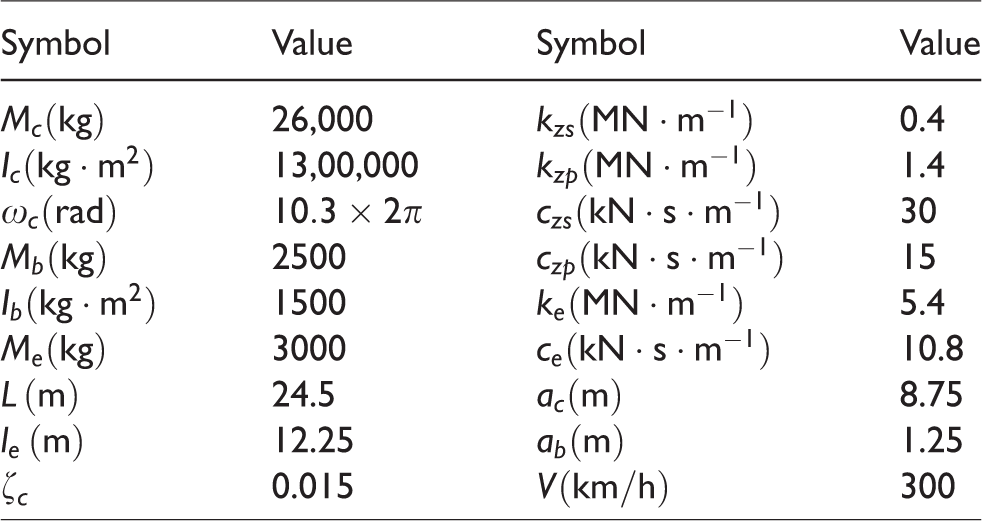
Figure 1 shows the vertical vibration model of vehicle–equipment coupling system.7,20 The model consists of an elastic carbody, an underframe suspended equipment, two bogies, and four wheelsets. The carbody is considered as a uniform Euler–Bernoulli beam, the primary and secondary suspensions of the railway vehicle are realized by Kelvin–Voigt-type systems, and the original scheme for the underframe suspension system uses the Kelvin–Voigt type. The parameters for a typical high-speed vehicle model are listed in Table 1.

Vertical vibration model of vehicle–equipment.
Model parameters of the railway vehicle.
The length of the carbody is 

The model considers the bounce 
The first vertical bending eigenfunction is


Therefore, the carbody vibration equation is
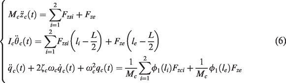

The bounce displacement of the suspended equipment can be expressed as

The equations for the bounce displacement and pitch movement of the bogies are


The systems of equations (6) and (8)–(10) can be expressed as

Using modal analysis method, the acceleration frequency response function (FRF) matrix of the vehicle can be written as

Considering the time lag characteristics of wheelset excitation, the acceleration FRF matrix, which includes wheelset excitation, can be expressed as follows
11


Thus, the acceleration FRF at any position 
Vibration reduction of the flexible carbody
Vehicle–equipment coupled vibration analysis
Figure 2 depicts the acceleration FRF curve of carbody center in three situations: without equipment, with rigid fixed equipment, and with elastic suspension equipment. 7 The peak value at 1.3 Hz is the bouncing modal of the carbody. The rigid body vibration of the carbody is not discussed here. When there is no equipment, the vertical bending frequency of the carbody is 10.3 Hz; when the equipment is rigidly fixed in the carbody center, the vertical bending frequency of the carbody decreases to 9.5 Hz due to the vibration of the equipment in phase with the carbody, and the vibration amplitude of the carbody decreases slightly at this frequency; and when the elastic suspension equipment is used, the car body no longer shows peak value at the previous vertical bending frequency, as it is replaced by a low-frequency peak and a high-frequency peak of 8.35 and 12.3 Hz, respectively. The low-frequency peak is due to the vibration of the equipment in phase with the carbody, increasing the total mass of the vibration. The high-frequency peak is due to the vibration of the equipment in opposite phase with the carbody, reducing the total mass of the vibration. Since the underframe equipment is elastically connected to the carbody, the equipment is regarded as a DVA, which changes the flexible vibration behavior of the carbody. 11

Acceleration frequency response of carbody center.
The effects of series stiffness on vehicle vibration
Figure 3 shows the suspension layout of the equipment, 


Suspension layout of the equipment: (a) Kelvin–Voigt type and (b) three-element type.
Figure 4 shows the relationship among the influence coefficient and the series stiffness and the excitation frequency. In the calculation, the damping coefficient of the shock absorber itself is
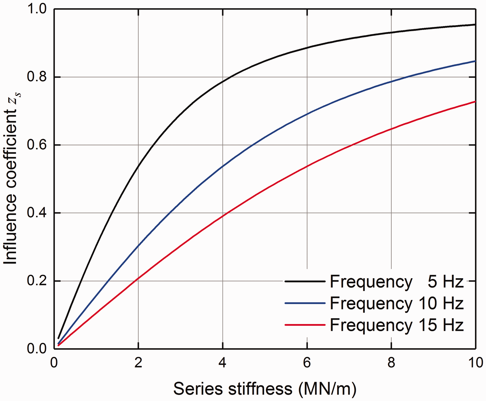
The curve of the relationship among the influence coefficient and the series stiffness and the excitation frequency.
The series stiffness affects the damping force of the shock absorber and therefore also affects the vibration of the carbody and equipment. Figure 5 depicts the effects of series stiffness on the vibration of carbody and equipment. As can be seen from Figure 5(a), with the increase in the series stiffness, the vibration amplitude of the carbody first decreases and then increases. When the series stiffness is

The effects of series stiffness on the vibration of (a) carbody and (b) equipment.
Vehicle–equipment simplified model considering the series stiffness of the shock absorber
The DVA model in this article considers the series stiffness, so the suspension system cannot be considered as a structure consisting of a damper and a spring in parallel (cf. Figure 6(a)). The structure presented in this article can be expressed as the three-element-type Maxwell model, as shown in Figure 6(b).17,25 In Figure 6,

Model of shock absorber system: (a) Kelvin–Voigt model and (b) three-element-type Maxwell model.
The carbody and the suspended equipment constitute a coupled system, and the suspension system is modeled by the three-element-type Maxwell model. The carbody is considered as an Euler–Bernoulli beam of mass 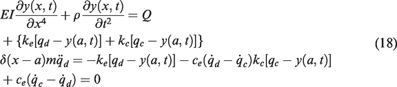
According to the modal analysis theory, the displacement of the beam can be expanded as

Suppose 
The forms of the steady-state solution are as follows

The FRF of the beam displacement can be written as


Then, the following parametric transformations are introduced

Consider the response when the point 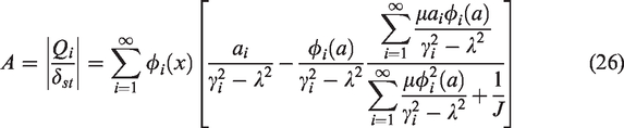

To minimize the maximum value of the main system amplitude amplification factor with given mass ratio 
From numerical analysis of equation (26), the optimal values of 
Therefore, the fixed-point theory can be used.26,27 From equation (29), the results show that the amplitude–frequency curve will pass through three points independent of the damping ratio, that is, the fixed point of the DVA. The amplitude–frequency curves with damping ratios of 0.1, 0.3, and 0.4 are randomly selected as shown in Figure 7. It is clear from the graph that the curves pass through three common points: P, Q, and R.
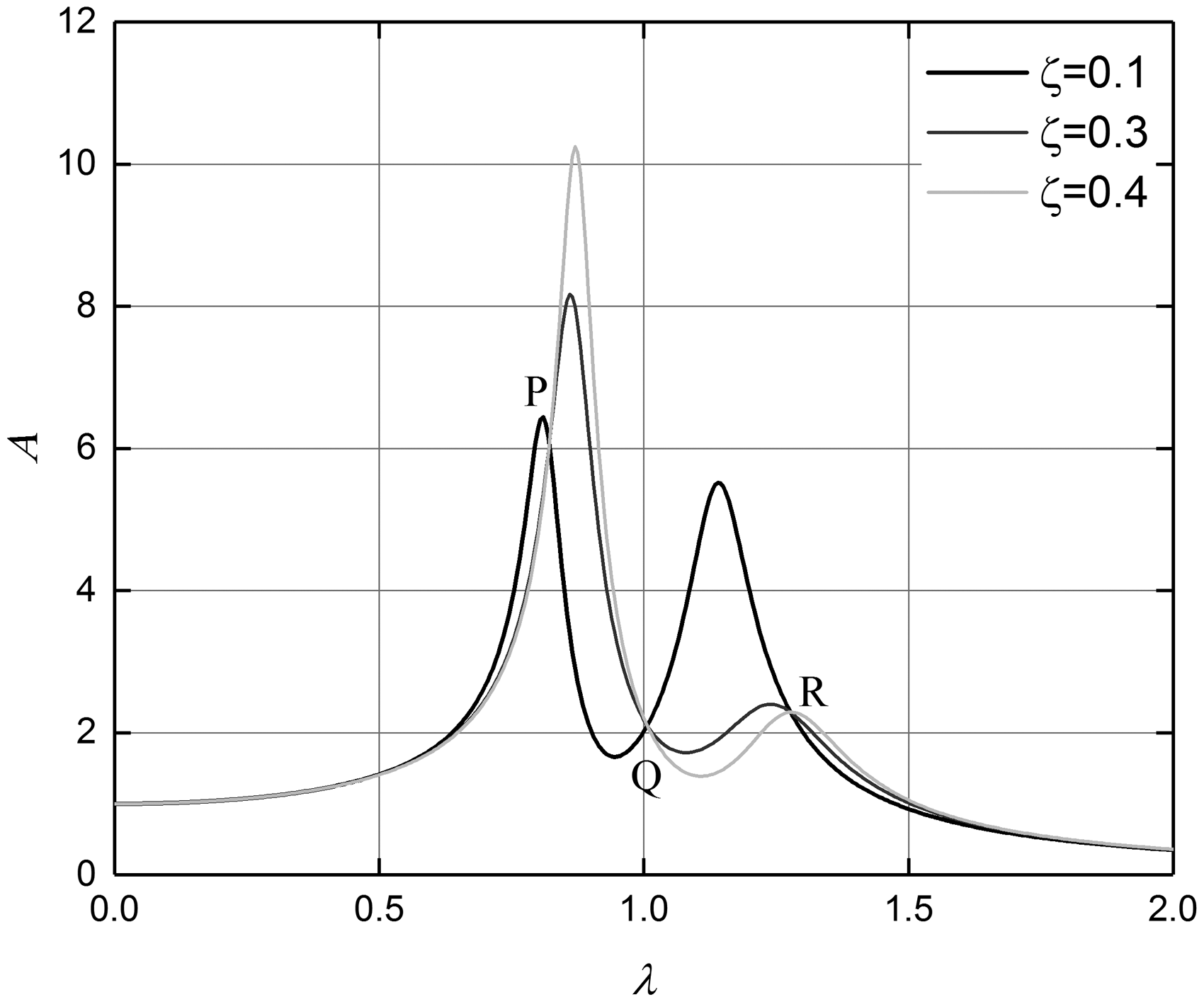
The amplitude–frequency curves under
Because the fixed points are independent of the damping ratio, it can be obtained when 

The amplitude–frequency curves of equations (31) and (32) are shown in Figure 8. As can be seen from the graph, the values of fixed points P, Q, and R differ by a sign on the amplitude–frequency curves of 

The amplitude–frequency curves under
To solve the values of the points P, Q, and R, the simultaneous formulas (31)–(33) are combined to obtain

For convenience, the real roots of three fixed points are, respectively, supposed as 
By adjusting the three points to the same height, the optimal tuning ratio can be obtained, which makes it possible to minimize the maximum value of the amplitude–frequency curve. At first, two of the points, P and R, are adjusted to the same height
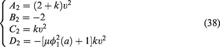
Then equation (35) can be rewritten as
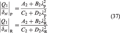
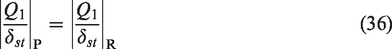
To verify equation (36), the following relation must be true

Accordingly, it is possible to obtain

Substituting equation (40) into (33)

Solving equation (41) for
yields

Substituting equation (42) into (35), as the resulting heights of the three fixed points can be rewritten as

Second, the optimal tuning ratio 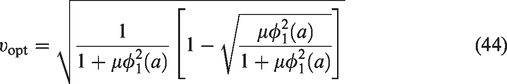
Substituting equation (44) into (40), the optimum value of 
When the three fixed points are adjusted to the same height, the optimal damping ratio can be achieved by adjusting the two resonance peaks to the same height.
28
Rewriting equation (29)


To solve the values of the optimum damping ratio and the amplitude magnification factor, let the height of the line be 
Simplified derivation using the approximate value in Asami and Nishihara
29
gives

And substituting equations (44), (45), and (48) into equation (46), we can obtain
30


Equation (50) should have two double roots. Therefore, rewrite as follows

Using Vieta’s theorem, get the following alternative expression

By eliminating the variables 

Substituting equation (48) into equations (54) and (55) yields the simultaneous equations 
Solving equation (56) for 
Substituting equation (57) into 
Solving equation (58) for 
By substituting equation (59) into (57), we can get


Then, the optimal damping and the minimized amplitude magnification factor are obtained

At this time, the optimal suspension parameters of Euler–Bernoulli beam with attached three-element-type DVA result are as follows


Figure 9 shows the amplitude–frequency curve under the optimal parameters above, which is denoted by the solid line. In order to illustrate the correctness and precision of the analytical solution, the numerical solution is also presented in this same figure. It can be clearly seen from the figure that the analytical and the numerical solution are almost identical, which also shows the correctness of the solution adopted in this article.

The amplitude–frequency curve with the optimal parameters
To prove the vibration reduction effect of the three-element-type DVA, the optimization results of the model proposed in this article are compared with the Kelvin–Voigt model.9–11,26 The amplitude–frequency curve is shown in Figure 10. It can be clearly seen from the figure that the DVA proposed in this article can effectively reduce the vibration amplitude at the same mass ratio and the same suspension position.

Comparison between the DVA in this article and the Kelvin–Voigt model DVA under
During the DVA design process, the weight and suspension position of the DVA are not arbitrary, and they are determined by numerous practical constraints, such as the space available for installation or the manufacturing cost. A smaller DVA weight or suspension position too far from the center of the beam will result in two natural frequencies (
The optimal design parameters of the three-element-type DVA can be expressed by equation (64). According to the benchmark parameters of Table 1, the optimal DVA parameters can be easily obtained based on vehicle–equipment dynamic model and model parameters, as shown in Figure 11.

The relationship between mass ratio and optimum parameters.
Therefore, the optimal design parameters of the elastic suspension equipment can be written as

Simulation analysis
Numerical analysis
In the actual operation of the railway vehicle, there is a time lag in the vertical excitation of track irregularity. The lag constant is determined by the vehicle spacing, wheelbase, and vehicle speed. Under the action of the suspension system, the geometric filtering effect will occur. The filtering frequency is calculated as follows
31
The null response frequency points

Figure 12 depicts the acceleration FRF curve of the carbody center at a running speed of 300 km/h. The first observation is that due to the influence of the geometric filtering effect, the vibration response of the carbody will have several maximum and minimum values. The extreme point frequency coincides with the filtering frequency in Table 2, and the pitch filter frequency

Acceleration FRF of the carbody center under 300 km/h.
Figure 13 shows the acceleration FRF curve of the underframe equipment at a running speed of 300 km/h. As it can be seen from Figure 10, both the DVA of the optimal Kelvin–Voigt type and the DVA of the optimal three-element type can effectively suppress the equipment resonance, but the effect of vibration reduction is almost the same. When the optimal Kelvin–Voigt-type DVA is used, the maximum FRF amplitude of the underframe equipment is reduced by 60.5%. When using the optimal three-element-type DVA, the maximum FRF amplitude of the underframe equipment is reduced by 59.3%.

Acceleration FRF of the underframe equipment under 300 km/h.
Figure 14 shows the relationship between mass ratio and acceleration FRF amplitude at the carbody center. The results show that with the increase in the mass ratio, the vibration amplitude of the vertical bending frequency caused by DVA will decrease, and the in-phase vibration amplitude will also decrease significantly. The smaller DVA weight will cause the two frequencies (
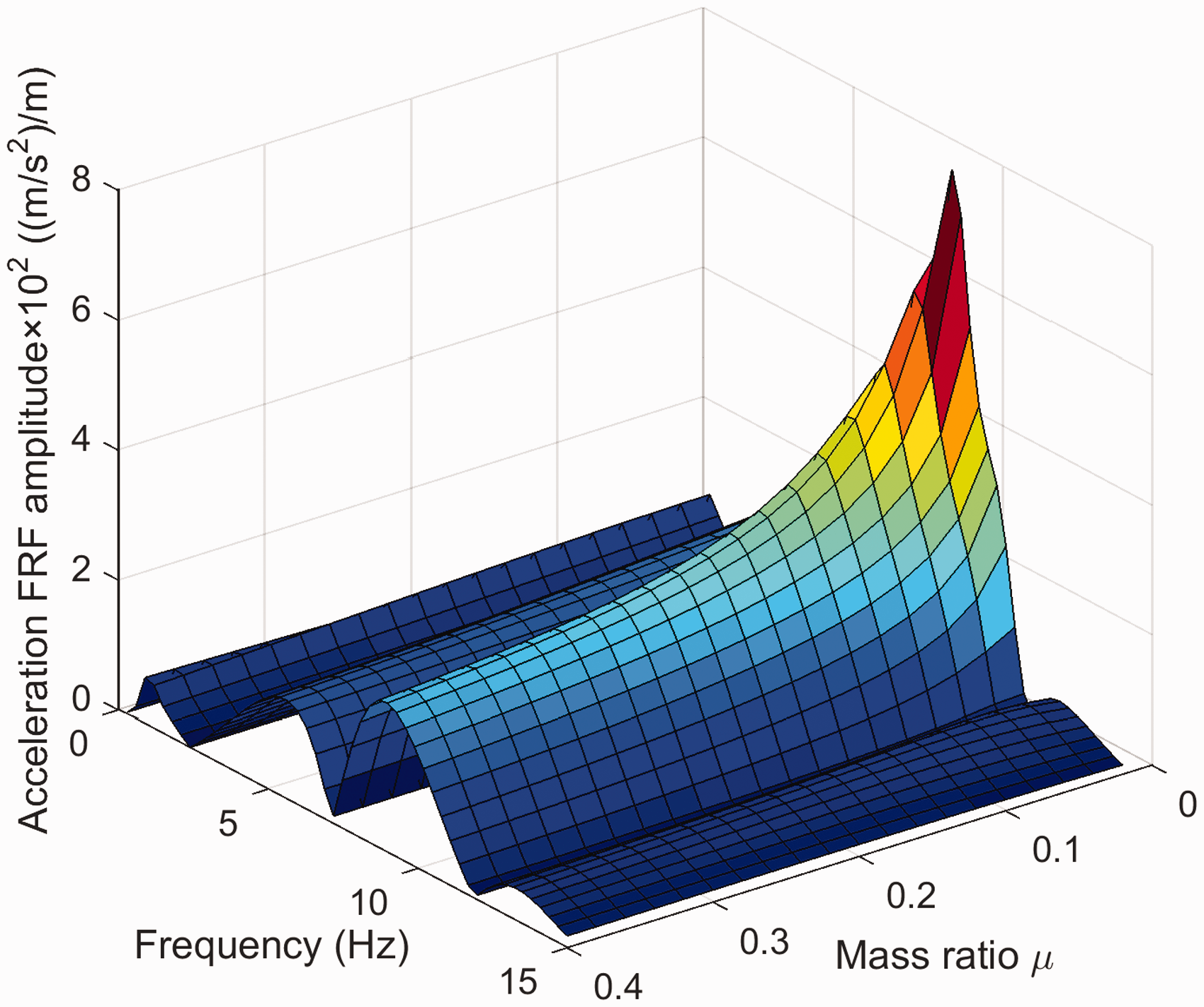
The relationship between mass ratio and acceleration amplitude.
Multi-body simulation
The 3D rigid-flexible coupled dynamics model has been established by combing the finite element model (FEM) software ANSYS and multi-body system (MBS) dynamics software SIMPACK in this article. The primary suspension is mainly modeled as parallel spring–damper elements, and in the vertical direction, the same type of element has been used to model the vertical bump stop. On the secondary suspension level, the air spring is also modeled with parallel spring–damper elements, and the yaw damper is established up as a serial spring–damper element considering the stiffness and damping of the rubber mounts. The same element type also characterizes the roll stabilizer bars. The established multi-body dynamics model is shown in Figure 15.

SIMPACK model of the vehicle–equipment system.
According to the contribution of the carbody elasticity to vibration energy, the carbody elasticity only considers low-order elastic modes, 31 where the first-order vertical bending frequency is 10.3 Hz. In this study, the mass of the equipment is 3000 kg, and the number of suspension points is 4. The traditional rubber spring parameters of the original scheme have been determined. Through the method of Huang et al., the suspension parameters of the Kelvin–Voigt-type DVA can be obtained. According to equation (64), the suspension parameters of the three-element-type DVA can be obtained. Table 3 lists these suspension parameter values.
Parameter value of the rubber spring.

DVA: dynamic vibration absorber.
Applying the fifth-grade track spectrum excitation of the United States to the dynamic model, the root mean square (RMS) value of the vibration acceleration of the carbody and equipment can be calculated under various speeds and compared with the Kelvin–Voigt-type DVA; the results are shown in Figure 16.

RMS value of vibration acceleration of the (a) carbody and (b) equipment.
From Figure 16(a), it can be seen that the vibration reduction effect of the two DVA models is not obvious when the speed is lower than 200 km/h, because the vehicle speed is not high and the carbody vibration is small. When the speed is higher than 200km/h, the three-element-type DVA can substantially reduce the vibration of the carbody. These two DVA models can also suppress the vibration of the equipment itself and can reduce the vibration of the carbody without deteriorating the working environment of the equipment.
Figure 17 shows the comparison between the calculation results of vehicle running stability Sperling index of the three-element-type DVA and Kelvin–Voigt-type DVA model for underframe equipment. The vehicle running stability index increases with speed; after the DVA model is adopted, the vehicle running stability index is significantly reduced. When the vehicle speed is 240–280 km/h, it has a good vibration reduction effect. Among them, the three-element-type DVA model can strongly restrain the vibration of the carbody and reduce the Sperling index.
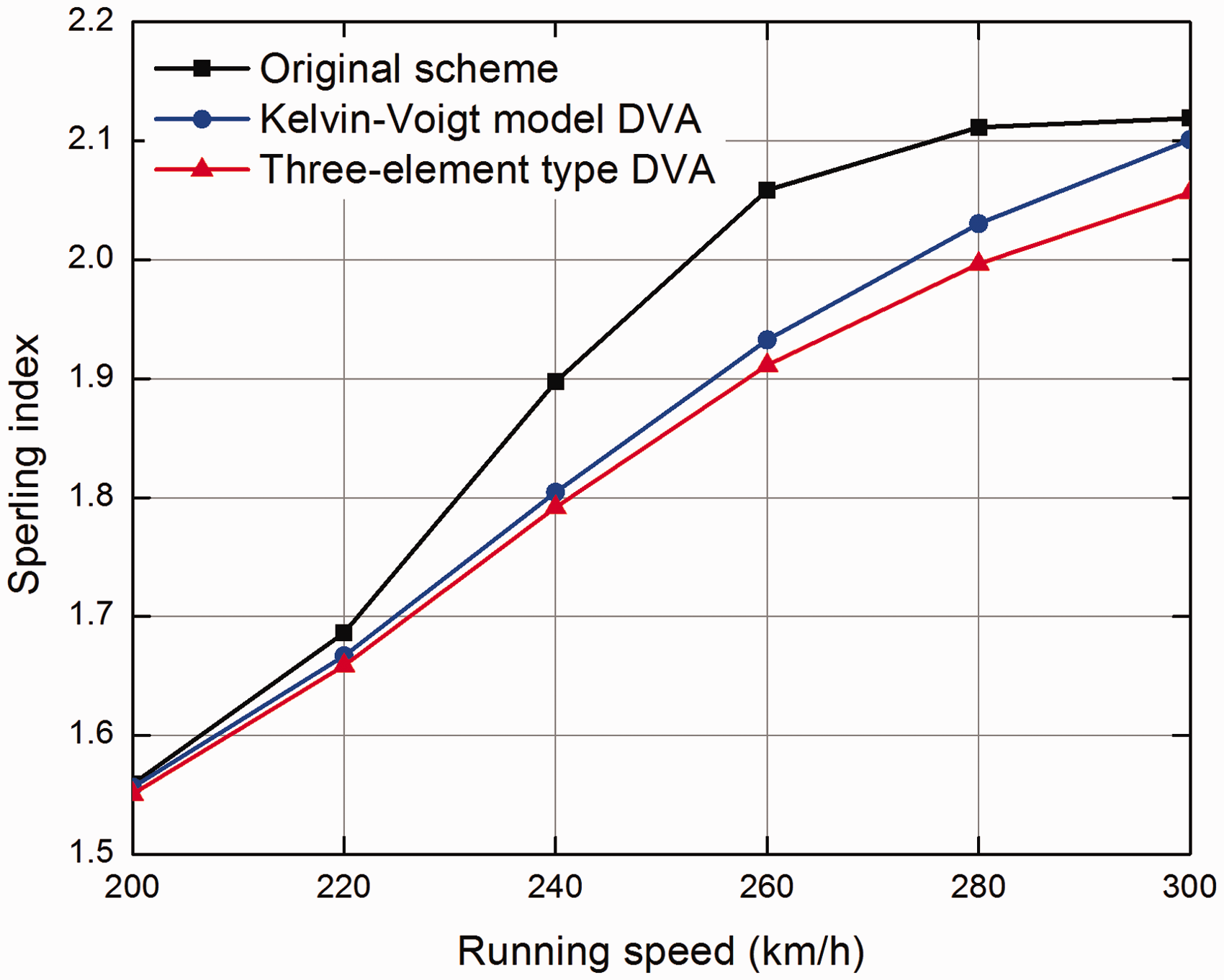
Vertical running stability Sperling index.
Conclusion
The underframe equipment is elastically suspended on the carbody, and the equipment behaves as a DVA. Therefore, DVA theory is applied to reduce the carbody resonance. Considering the series stiffness of the shock absorbers, an optimal DVA of the three-element-type Maxwell model for general beam system is investigated. Based on the fixed-point theory, the optimal design parameters are obtained, and the three-element-type DVA model parameters of the underframe equipment are designed accordingly. Comparison and analysis of the vehicle running stability and RMS value of vibration acceleration of the carbody using the three-element-type DVA model and the Kelvin–Voigt-type DVA model of the underframe equipment are performed. The results show that compared with the Kelvin–Voigt-type DVA model, the underframe equipment using the three-element-type DVA model can substantially reduce the elastic vibration of the carbody and improve the vertical running stability of the vehicle. The series stiffness affects the damping force of the shock absorber and therefore also affects the vibration of the car body and equipment; the appropriate series stiffness can be selected to make the vibration level of carbody and equipment meet the engineering requirements. The results provide a new approach for the design of the underframe equipment of three-element-type Maxwell model.
The use of the three-element-type DVA to reduce the carbody structural vibrations in the rail vehicles is a new approach that falls within the area of research studies on vehicle running stability improvement by utilizing the passive systems. This article only uses simulation to verify the vibration reduction ability of the three-element-type DVA model. The future research needs to use field tests to answer to the question linked to the influence of the three-element-type DVA model on vehicle vibration and ride comfort.
Footnotes
Handling Editor: David Chalet
Acknowledgements
The authors thank Manuel Perez for his linguistic assistance during the preparation of this manuscript.
Declaration of conflicting interests
The author(s) declared no potential conflicts of interest with respect to the research, authorship, and/or publication of this article.
Funding
The author(s) disclosed receipt of the following financial support for the research, authorship, and/or publication of this article: This work was supported by the Science and Technology Research Project of Chongqing Municipal Education Commission (Grant No. KJQN201901323), Talent Introduction Project of Chongqing University of Arts and Science (Grant No. R2019FJD02), and Chongqing Municipal Natural Science Foundation (Grant No. cstc2019jcyj-msxm X0730).