
Abstract
Small turbines must operate at high rotational speeds to generate adequate output power. In this study, a radial inflow turbine using R245fa as the working fluid is miniaturised and is designed to have a rotational speed of 30,000 r/min. The organic Rankine cycle system is not simplified, and a preheater and a superheater are installed. The turbine is experimentally analysed in the organic Rankine cycle system. The experimental results show that with an increase in the inlet pressure, the turbine output power and system efficiency increase; moreover, the turbine efficiency first decreases and then increases slightly after the pressure exceeds 1.5 MPa. The turbine efficiency decreases first and then increases and attains the minimum value at an inlet temperature of 100°C–105°C. When the flow rate is 0.82 m3/s, the speed reaches its maximum value of 28,000 r/min, and a maximum output power of 17.37 kW is generated. The maximum efficiency of the turbine is 0.885 and that of the system is 0.1625. The experimental data and design parameters of the turbine provide a reference for further design optimization.
Introduction
In recent years, with the increasing shortage of energy and an increasing focus on environmental protection, energy efficiency and clean energy have attracted considerable attention as research topics. Organic Rankine cycle (ORC) power generation is an environmentally friendly power generation technology that does not pollute the environment. 1 ORC power generation systems utilise the low boiling point of organic fluids to generate electricity, such as by using low-temperature industrial waste, 2 geothermal energy, 3 biomass 4 and solar energy 5 as heat sources. As ORC systems use water and air in the environment as cold sources, they do not consume non-renewable resources such as fossil fuels and nuclear energy.
To convert low-temperature heat energy into available energy, Yamamoto et al. 6 used R123 instead of water as the circulating fluid in a Rankine cycle experiment. They observed that the R123 system exhibited better performance than water system when the temperature was lower than 120°C. In order to improve the total power generation, Shams Ghoreishi et al. 7 compared four Rankine system arrangements and six refrigerants and selected the best arrangement for each refrigerant. Therefore, ORC has been widely studied and applied in the field of low-temperature heat recovery.
In ORC systems, the key component is the expander. The expansion process of organic fluids occurs in the expander, which converts the internal energy of the fluid into mechanical energy. Therefore, the efficiency and performance of the expander have a direct impact on the performance of the ORC system. According to their movements and structures, expanders can be divided into two types: the velocity type and the volume type. 8 Velocity expanders generate high speed by passing high-temperature and high-pressure fluids through nozzles and blades, thus generating mechanical energy. Example includes turbine expanders, which are often used in large- and medium-sized systems.9,10 Volumetric expanders expand the fluid directly, use the high pressure generated to rotate the shaft and generate mechanical energy. Examples of volumetric expanders are the scroll expander and the screw expander. Therefore, volumetric expander is widely used in micro-ORC power generation systems. 11
Lemort et al. 12 conducted an experimental study on a closed scroll expander with R245fa as the working fluid. Their experimental results showed that the adiabatic efficiency of the expander was 71.03%, and the maximum output power was 2.2 kW. Based on the measured data, a semi-empirical theoretical model of the scroll expander was defined. Quoilin et al. 13 constructed a thermodynamic model for the scroll expansion mechanism that is applied to the ORC system. Zhe-Ming et al. 14 elaborated and summarised the results obtained by several researchers regarding various aspects of scroll machinery. Kang 15 performed experiments using a radial turbine as an expander and R245fa as the working fluid in an ORC system. The experimental results showed that the system could generate an output power of 32.7 kW, while the system efficiency and turbine insulation efficiency could attain values of 5.22% and 78.7%, respectively. Harinick et al. 16 numerically simulated the flow characteristics in an ORC radial turbine nozzle with toluene, which has a high expansion ratio, as the working fluid. The thermal properties of the working fluid were accurately estimated, and the effects of different solvers, thermodynamic models and turbulence models on the flow were analysed.
Numerical investigations and three-dimensional simulations play an important role in turbine design and in the improvement of system performance. Hamdi et al. 17 studied a radial inflow two-stage turbine through an accurate computational fluid dynamics simulation interfaced with thermodynamic models and improved the numerical model based on the experimental results.
Lim et al. 18 designed and optimised the turbine generator for an ORC system at a 200 kW grade, through rotor dynamic analysis, rotor balancing, ball bearing stabilisation and spin tests. Finally, the performance of the improved turbine was evaluated in the ORC system; these procedures may be used as a reference to develop a modified ORC turbine.
Bao and Zhao 19 summarised the advantages and disadvantages of various expanders used in the ORC system. They indicated that scroll and multi-vane expanders are applicable for power outputs smaller than 10 kW, while turbine and screw expanders are suitable for power outputs greater than 20 kW. In previous studies, turbines have been used in large- and medium-sized ORC systems, and these turbines generated more power and attained higher efficiencies in the large-scale systems. For turbines, there is almost no application of ORC system less than 20 kW.
Radial turbine is a kind of speed expander that has the characteristics of high speed and high efficiency. Small turbines must have large rotational speed to produce sufficient output power. Otherwise, extremely large volumes will reduce its efficiency. For the same displacement, the turbine with higher rotational speed has greater output power and efficiency. A radial inflow turbine designed to have a speed of 30,000 r/min and an isentropic efficiency greater than 85% is adopted. The designed turbine is miniaturised and tested in the ORC system with the maximum rated output power of 20 kW.
In the case of a low-temperature heat source (<150°C), the efficiency of the ORC power generation system is low; improving the efficiency of expander can effectively improve the power generation capacity of the system. The turbine is miniaturised such that it may be used in a small ORC system. For turbines, the energy loss is primarily due to the design being unsuitable for the specific operating conditions of the system. According to the specific experimental conditions, considering the thermal properties of R245fa (i.e. evaporation temperature of 90°C–125°C, condensation temperature of 25°C–40°C, inlet turbine superheat of 5°C, inlet pressure of 1.74 MPa, expansion ratio of 10, maximum flow rate of 3000 L/h and output power of 20 kW), a radial inflow turbine suitable for the ORC system is designed and tested in the ORC power generation system. The ORC system is designed to replicate large-scale, commercially used systems, to reproduce real-world scenarios. A preheater and a superheater are installed, and the system is not simplified.
Turbine generator
The design conditions of the radial inflow turbine are determined according to the operating conditions of the ORC system. Before the turbine is designed, the ORC power generation system parameters are calculated, and the initial design parameters of the turbine are obtained, as shown in Table 1.
Design conditions of 20-kW-grade organic fluid turbine.

The main components of the radial turbine generator are the impeller, nozzle, generator and external volute. In order to improve the efficiency, the turbine and generator are connected through the main shaft and are fully enclosed. Figure 1 shows the structure of the radial inflow turbine. The impeller and nozzle are the most important components that affect the performance of the turbine. The function of the nozzle is to change the flow direction of the fluid and to accelerate it by using the cascade around the nozzle. The radial annular nozzle is adopted and is designed using an empirical design method. 20 Figure 2 shows the simulation diagram of the impeller and nozzle. The aerodynamic characteristics of the nozzle are obtained through simulation and cascade blowing experiments on the mature blade profile. 21 It should be noted that R245fa belongs to the category of organic fluids having a high molecular weight and low sound velocity; thus, its expansion ratio is relatively large. Therefore, a cascade suitable for transonic flow is selected very carefully. The turbine was manufactured by Suzhou Xida Turbine Energy Technology Co., Ltd. Figure 3 shows the designed radial inflow turbine generator.

Structure of radial inflow turbine.
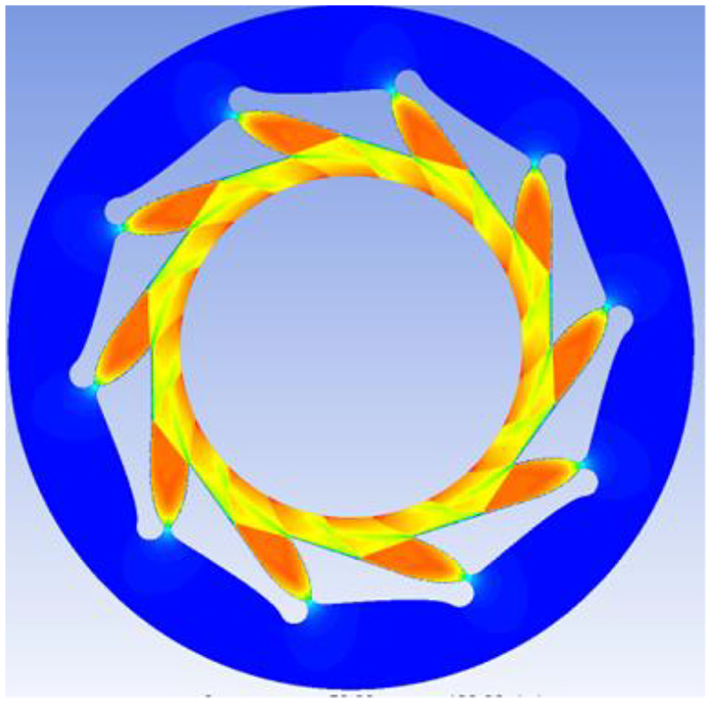
Simulation diagram of impeller and nozzle.
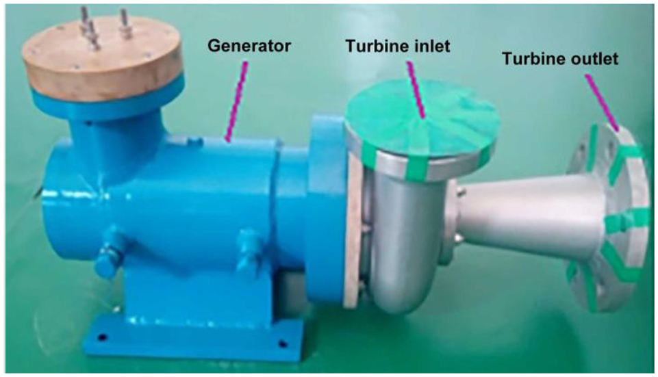
Photo of turbine generator.
In order to improve the shaft efficiency of the turbine generator and increase the actual power generation, gas ceramic bearings are adopted owing to the low friction in gas bearings, the wide operating temperature range and the low heat generation at high speeds.22,23 A high-speed generator is used to adapt to the high speed of the turbine. According to previous studies, although power loss is caused by the high frequency of the generator, it also keeps within a reasonable range with the progress of technology.24–26
ORC power generation system
The ORC power generation systems are mainly composed of evaporators, condensers, preheaters, superheaters, working fluid pumps, circulating water pumps, expanders and generators. 27 At present, the research on ORC power generation technology for medium- and high-temperature waste heat sources (>150°C) is mature. For low-temperature heat sources, the efficiency of ORC power generation systems has to be improved.28–31 The preheater and superheater adopt plate heat exchangers, and the evaporator and condenser adopt full liquid types. The specific parameters of the evaporator are shown in Table 2. From the comparisons made before and after installation, it is found that the installation of preheaters and superheaters can improve the system efficiency, and the installation of superheaters can further protect the turbine from the liquid impact phenomenon.
Evaporator performance parameters.

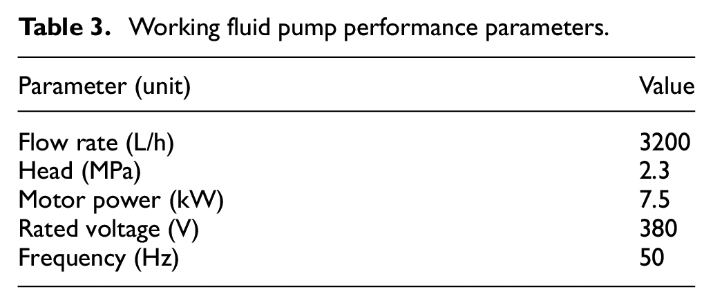
When the evaporation temperature is 120°C and the condensation temperature is 35°C, the pressure drop in the working medium reaches the maximum value of 1.72 MPa. JMD series hydraulic diaphragm pump of Nanfang Pump Co., Ltd. is selected as the working fluid pump. The specific parameters of the working fluid pump are shown in Table 3.
Working fluid pump performance parameters.
The ideal ORC consists of four main thermodynamic processes (Figure 4): constant-pressure heating (6s–1), isentropic expansion (1–2s), constant-pressure condensation (2s–5), and isentropic compression (5–6s). Owing to the resistance loss during expansion and compression, the actual expansion and compression processes are not isentropic. In Figure 4, points 1–2 indicate the actual expansion process for the working fluid in the expander, and points 2–4 indicate the heat-release process for the working fluid in the condenser. To ensure that the working fluid entering the pump is in the liquid state and to avoid cavitations, the supercooling process 4–5 is added. The points 5–6 represent the pressurisation process of the working fluid, 6–7 the preheating process, 7–8 the evaporation process, and 8–1 the superheating process. Superheated organic steam enters the expander to continue the following cycle. In addition, 9–12 and 13–16 represent the change trends in the heat source and cold source before and after the heat exchange.

T–S diagram of ORC power generation system.
Figure 5 shows the schematic diagram of the ORC power generation system. The pressure loss of the ORC system is calculated and the simulation is performed to reduce the power consumption of the circulating water pump and working fluid pump, as shown in Figure 6. Boiler steam is used to replace industrial waste heat as the heat source of the system. The heat source used is saturated steam with pressure above 0.45 MPa and a flow rate higher than 980 kg/h. Figure 7 shows the photo of the ORC power generation system.

Schematic diagram of ORC power generation system.

Three-dimensional simulation of ORC power generation system.

Photo of ORC generation system.
The ideal expansion process in the expander is the isentropic expansion; however, there is irreversible loss in the actual expansion process. For this purpose, isentropic efficiency is defined as equation (1)

where h1, h2 and h2s are the enthalpies of inlet, outlet and isentropic expansion outlet of the turbine, respectively, in kJ/kg. In the actual expansion process, the isentropic efficiency will change with pressure, temperature and other parameters. In the ORC system, the change in this value is small and can be regarded approximately as an invariant. The actual expansion power Ws can be calculated by equation (2)

where mf is the organic fluid mass flow rate (kg/s).
In the low-temperature waste heat ORC system, the expansion power directly reflects the function of the turbine, while the output power of the whole system depends on the generated power and consumed power of the system. The equation is as follows

where Wnet is the net output power of the ORC system in kW and Wfp is the power consumption of the organic fluid pump.
Another important thermodynamic parameter of the ORC system is the thermal efficiency of the system, which is the ratio of the net output power of the system to the heat absorbed by the organic fluid from the heat source

where Qe is the heat absorbed by the organic fluid from the heat source.
According to the type of fluids in the system, the circulation consists of three parts: the organic fluid cycle, steam cycle and cooling water cycle.
Organic fluid cycle. First, after preheating, the organic fluid evaporates into the high-pressure organic steam in the evaporator, and then flows into the expander after being superheated in the superheater. After the heat exchange in the superheater, saturated steam enters the preheater through pipeline 1. Second, the high-pressure organic steam forces the expander blade to rotate and then drives the generator to generate the electric power. Finally, the organic steam from the expander outlet condenses into liquid in the condenser, before flowing into the refrigerant tank. The organic fluid is driven from the tank to the preheater by the pump and then the cycle is repeated. Excess organic fluid can be stored in the refrigerant tank for adjusting the flow rate.
Steam cycle. To increase the energy utilisation level of the waste heat steam, the steam is divided into two parts: the smaller part enters the superheater and the larger part enters the evaporator. After heat exchange with the organic fluid, the two parts of steam are mixed and then flown into the preheater to continue heating the organic fluid pumped from the refrigerant tank. Finally, the steam from the preheater condenses into liquid water in the condensation tank to complete the steam cycle.
Cooling water cycle. The cooling water is pumped into the condenser from the cooling tower by a centrifugal pump. After absorbing the heat of the organic fluid, the temperature of the cooling water rises, and the counter flow cooling tower releases the heat such that the heat circulation is repeated.
In order to test the performance of the turbine and ORC power generation system, the parameters of the system are set after the designing and calculations. The measurement uncertainties of temperature, pressure, cooling water and R245fa mass flow rate were ±0.6%, ±0.48%, ±0.28% and ±0.22%, respectively. The experimental parameters are shown in Table 4.
Parameters of the ORC power plant system.

ORC: organic Rankine cycle.
Experimental results and analysis
In the experiments performed on the radial inflow turbine and ORC power generation system, the temperature reduction in the turbine, flow rate, output power, turbine efficiency and system thermal efficiency are analysed. The effects of inlet pressure, inlet temperature and rotational speed on the performance of the turbine and system are analysed experimentally. In the experiment, the steam flow rate is regulated by adjusting the opening degree of the steam valve, and the steam temperature is regulated through the boiler. The flow rate of R245fa is regulated through frequency conversion of the working fluid pump. It should be noted that the power loss in the generator is not considered in the experiment, and the efficiency of the turbine generator is assumed to be the efficiency of the turbine.
Influence of inlet pressure of turbine
The inlet pressure of the self-designed turbine is 1.74 MPa. In order to evaluate the performance of the designed turbine and system, the inlet pressure was gradually increased from 1.2 to 1.74 MPa to study the influence of inlet pressure on turbine output power, efficiency, flow rate and system efficiency. Here, the temperature of R245fa is controlled between 112°C and 117°C. Figure 7 depicts the curves showcasing the influence of the change in turbine inlet pressure on the turbine output power and flow rate.
As can be seen from Figure 8, with the increase in inlet pressure, the output power and flow rate of the turbine increase. The output power increases slowly until an inlet pressure of 1.4 MPa, and then increases rapidly, and after 1.54 MPa, it decreases. The maximum output power of the turbine is 17.1 kW. The flow rate increases rapidly until an inlet pressure of 1.35 MPa, and then decreases, before attaining a stable value of 0.833–0.87 m3/s.

Effect of inlet pressure on turbine output power and flow rate.
Figure 9 shows the effect of the change in turbine inlet pressure on turbine efficiency and system efficiency. The temperature of R245fa ranges from 112°C to 117°C, and the results of Figures 8 and 9 are from the same experimental process, thus they can be analysed together. From Figure 9, it can be seen that the change trends in turbine efficiency and system efficiency are opposite. Turbine efficiency decreases gradually with the increase in inlet pressure and then increases slightly when the pressure is greater than 1.5 MPa. The maximum turbine efficiency is 0.88 and the minimum is 0.775. This is the result of the interaction of turbine inlet pressure and flow rate. With the increase in inlet pressure and flow rate, the output power increases, resulting in the increase in turbine efficiency. After the pressure becomes greater than 1.5 MPa, the turbine efficiency decreases, which is caused by the fact that the inlet pressure value of 1.5 MPa is greater than the optimal pressure of the turbine, thus R245fa does not fully expand and the energy loss increases. It was found that the inlet pressure does not reach the design pressure of 1.74 MPa and the turbine efficiency decreases. The system efficiency increases with the increase in the inlet pressure and attains the maximum value of 0.158 when the inlet pressure is 1.55 MPa. The increase in system efficiency is mainly caused by the increase in the turbine output power according to the analysis of equation (4) and Figure 8.

Effect of inlet pressure on turbine efficiency and system efficiency.
Influence of inlet temperature of turbine
To study the influence of inlet temperature on turbine performance and system efficiency, the cooling water temperature is maintained at 20°C, while the inlet pressure is controlled between 1.45 and 1.58 MPa. The flow rates are maintained at 0.67, 0.75 and 0.86 m3/s. Referring to the thermophysical properties of R245fa, the inlet temperature of the turbine is varied between 90°C and 125°C. Figure 10 shows the influence of changes in the inlet temperature on the turbine output power. It can be seen that with increasing inlet temperature, the output power of the turbine increases. The increase in inlet temperature is accompanied by an increase in the flow rate, which leads to an increase in the output power of the turbine. The effects of inlet temperatures of 125°C and 90°C on the output power are compared. For the flow rates of 0.67, 0.75 and 0.86 m3/s, the power increases by 3.65 (∼47%), 4.275 (∼42.5%) and 2.67 kW (∼18.3%), respectively. It can be observed that the influence of the inlet temperature on the output power decreases with increasing flow rate. The trends of the three curves are similar; when the flow rate is 0.86 m3/s, the slope of the corresponding curve is minimum.

Effect of inlet temperature on turbine output power.
Figure 11 shows the influence of inlet temperature on the turbine and system efficiencies. From the variation curves of the turbine efficiency under three different flow rates, it is observed that the turbine efficiency first decreases and then increases with increasing inlet temperature and finally remains unchanged or decreases slightly. The inflection point of the turbine efficiency appears near the inlet temperature of 100°C–105°C; within this temperature range, a smaller flow rate leads to a higher turbine efficiency. Based on an analysis of the inflection point, the turbine efficiency decreases owing to the increase in the enthalpy of unit working fluid R245fa and the small increase in power output in the early stage. In the later stages, the efficiency increases because the temperature becomes similar to that of the design condition. Owing to the thermophysical properties of R245fa and the design conditions of the turbine, the turbine efficiency remains unchanged or decreases slightly after the inlet temperature exceeds 120°C, and a maximum turbine efficiency of 88.4% is achieved. The system efficiency increases with increasing inlet temperature. Before the inlet temperature of 110°C, the efficiency increases rapidly and then stabilises above 14.2%. A maximum system efficiency of 15.4% is attained. Because the irreversible loss during the evaporation and condensation processes in the heat exchanger decreases with the increase in temperature, increasing the exergy efficiency of the evaporator leads to an increase in the enthalpy of the fluid entering the turbine. Comparing the three system efficiency curves under different flow rates, it can be seen that the system efficiency increases as the flow rate becomes similar to that of the design condition.

Effect of inlet temperature on turbine efficiency and system efficiency.
Influence of rotational speed
The radial turbine is a high-speed impeller machine with a designed maximum rotational speed of 30,000 r/min. A change in the rotational speed considerably affects the output power and efficiency of the turbine, consequently affecting the performance of the power generation system. The inlet temperature of the turbine is 120°C, and the outlet pressure is 0.174 MPa. Upon increasing the flow rate of the working fluid pump from 0.615 to 0.82 m3/s, the turbine rotational speed changes from 12,000 to 28,000 r/min. The temperature drop and the variation in the output power of the turbine are shown in Figure 12.
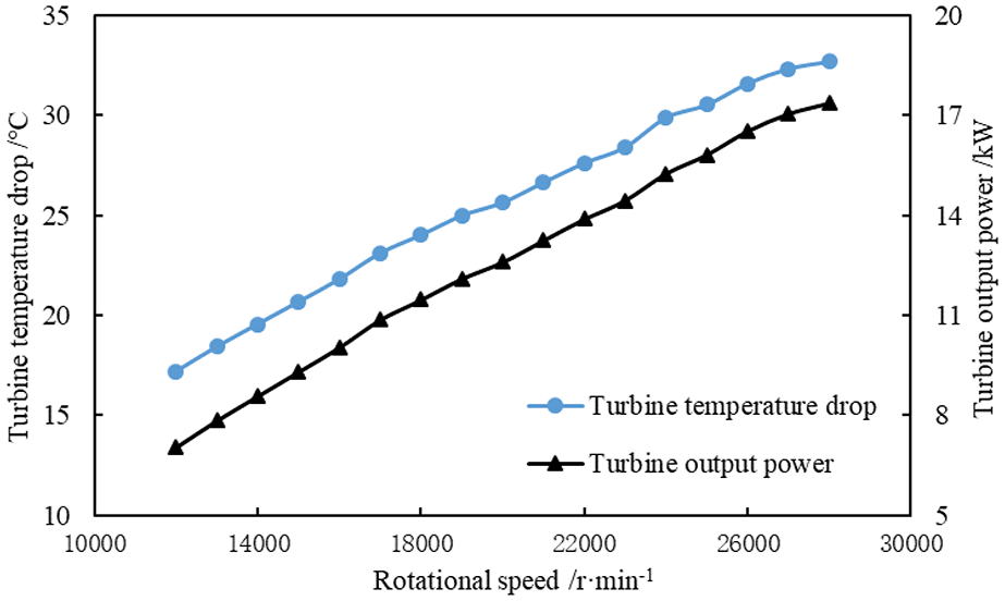
Effect of turbine speed on turbine temperature drop and output power.
With the increase in R245fa flow rate, the turbine rotational speed increases from 12,000 to 28,000 r/min, and the temperature drop and output power of the turbine also increase. When the flow rate is 0.82 m3/s, the turbine speed increases to 28,000 r/min; the temperature drop reaches the maximum value of 32.7°C and the output power reaches the maximum value of 17.37 kW. With the increase in rotational speed, the turbine can convert more thermal energy into mechanical energy. The increase in rotational speed makes the expansion process more similar to the design condition, thereby reducing various losses.
The influence of turbine speed on the turbine efficiency and system efficiency are shown in Figure 13. The turbine and system efficiencies increase with an increase in the rotational speed. When the rotational speed increases from 12,000 to 28,000 r/min, the turbine efficiency increases from 0.53 to 0.885, and the system efficiency increases from 0.123 to 0.1625.

Effect of turbine speed on turbine efficiency and system efficiency.
Conclusion
According to the thermophysical properties of R245fa, temperature range of the heat source, inlet pressure, and output power, the design of the radial turbine is executed. Small turbines must have large rotational speeds to produce adequate output power. The radial inflow turbine is miniaturised and designed with a rotational speed of 30,000 r/min. A cascade suitable for transonic flow is selected. High rotational speed requires high-performance steel, wear-resistant technology and machining accuracy. In order to improve the turbine efficiency, the turbine and alternator are coaxially connected and completely enclosed.
The ORC system is simulated in order to reduce pressure loss. The ORC system is not simplified. From the comparisons made before and after installation, it is observed that the installation of the preheater and superheater can improve the system efficiency, and the installation of the superheater can further protect the turbine from the liquid impact phenomenon.
When the turbine inlet temperature is 112°C–117°C, the flow rate, output power and system efficiency increase with increasing inlet pressure. The turbine efficiency gradually decreases with increasing inlet pressure. It was observed that the inlet pressure does not attain the design value of 1.74 MPa and that the turbine efficiency decreases. After the pressure exceeds 1.5 MPa, the turbine efficiency increases slightly, and maximum and minimum efficiencies of 0.88 and 0.775, respectively, are attained.
When the turbine inlet pressure is maintained between 1.45 and 1.58 MPa and the flow rate is maintained at 0.67, 0.75 and 0.86 m3/s, respectively, the increase in inlet temperature is accompanied by the increase in flow rate, which further leads to the increase in the output power of the turbine. With the increase in turbine inlet temperature, the turbine efficiency first decreases and then increases, and obtains the minimum value near the inlet temperature of 100°C–105°C, and at the same temperature, the flow rate is smaller while the efficiency is higher.
When the turbine speed increases from 12,000 to 28,000 r/min, the temperature drop and output power of the turbine increase. When the flow rate is 0.82 m3/s, the turbine rotational speed increases to 28,000 r/min; the temperature drop reaches the maximum value of 32.7°C; and the output power reaches the maximum value of 17.37 kW. The turbine efficiency and system efficiency increase with the increase in rotational speed, attaining maximum values of 0.885 and 0.1625.
Footnotes
Appendix 1
Handling Editor: Jose Ramon Serrano
Declaration of conflicting interests
The author(s) declared no potential conflicts of interest with respect to the research, authorship and/or publication of this article.
Funding
The author(s) received no financial support for the research, authorship and/or publication of this article.