
Abstract
The field of electronic device applications is becoming more and more extensive. With the development of science and technology and the improvement of the integration of electronic components, local heating is becoming more and more serious. If heat cannot be discharged immediately, it will cause heat to accumulate, causing the temperature of each component to exceed the limit. The reliability of electronic equipment is greatly reduced. Especially in important fields such as military and aerospace, the thermal reliability of electronic components is higher. The research results show that increasing the Reynolds number is helpful to reduce the overall temperature and thermal resistance of the heat sink, but the increase of the Reynolds number and the decrease of the thermal resistance value are gradually flat. The design concept of material reduction has a significant impact on processing and cost. The results of this article show that selecting the appropriate heat sink fins and matching the specific Reynolds number can effectively improve the heat transfer performance of the heat sink.
Introduction
The field of electronic device applications is becoming more and more extensive. With the development of science and technology and the improvement of the integration of electronic components, local heating is becoming more and more serious. If heat cannot be discharged immediately, it will cause heat to accumulate, causing the temperature of each component to exceed the limit. The reliability of electronic equipment is greatly reduced. Especially in important fields such as military and aerospace, the thermal reliability of electronic components is higher. At present, the failure rate of electronic components increases with the increase of temperature, so the higher the temperature rise, the worse the reliability. Shah et al. 1 used numerical analysis to investigate the situation of flat-type heat sinks to find the optimal central fin geometry and air mass flow rate. The results show that during the same air mass flow rate, the improved stepped heat sink has higher thermal efficiency than the general heat sink and has a lower pressure gradient, which makes the heat source temperature improve. Sathyamurthy et al. 2 used nozzle to impact the center of the fin, using the κ–ε turbulence model, and comparing the experiment with the simulated analysis. The results show that when Re > 11,000, changing the fin length and cross-sectional area causes the internal flow velocity to be fast and the pressure drop to be large, resulting in eddy current, circulation, and reflow, which have an effect on thermal efficiency. Jonsson and Palm 3 explored three different types of heat sinks, changing the fin width and height when 2000 < Re < 14,000. The results show that in the absence of lateral bypass (zero bypass), the thermal resistance between the experimental data and the relationship is less than 10%, as shown in Figure 1, and the pressure drop is within 20%. Leon et al. 4 explored the pressure drop caused by fin flow resistance. The results show that using a heat sink with a small flow resistance, when Re ≧ 800, it can help the flow of fluid inside the fin and can accelerate the removal of heat; otherwise, if Re < 100, the fin shape has a lesser impact. Leon et al. 5 explored the thermal efficiencies between three different types of fins with linear fins, staggered rectangular fins, and staggered cylindrical fins. The results show that the staggered heat sink uses a circular heat sink to significantly improve aerodynamic efficiency. For the same cooling rate, the aerodynamic efficiency of the circular staggered heat sink may be 2.80 times that of a rectangular in-line heat sink. Therefore, in order to reduce the flow resistance, a circular heat sink is recommended for all heat sinks with a staggered layout. The beneficial effect of the rounded fins only occurs when the Reynolds number is above 800. Morega et al. 6 explored the optimal distance and plate number of flat fins in a fixed volume and plate spacing in natural convection. The results show that when the flat fins are placed at equal distances at 100 < Re < 10,000, the flat fins have an optimized heat dissipation performance. Harahap et al. 7 explored the heat dissipation fins of five rectangular arrays by changing the fin spacing, length, height, thickness, and number of arrays, and using the dimensionless similarity analysis to derive the data. The results show that the key parameters affecting heat dissipation are fin spacing and length. Narasimhan and Majdalani 8 used electronic cooling simulation software to simulate the heat dissipation of natural convection plate types and array column fins. The results show that the fin temperature distribution and the exit velocity situation are clearly visible when the three-dimensional graphic is displayed. Sara 9 explores the heat dissipation efficiency of staggered column fins. By changing the internal fin spacing and the distance from the nozzle to the fin, when the fin spacing is reduced from the nozzle to the fin, the internal average Nu number is the friction factor is increased, and in the case of low Reynolds number, the staggered array fins have better heat dissipation performance. Brignoni and Garimella 10 explored the distance from nozzle to fin, different nozzle caliber, and Reynolds number and found the best thermal condition by experimental method. The results show that the smaller diameter nozzles have a better heat transfer rate when the fixed Reynolds number is applied; the smaller nozzles have a lower thermal resistance value when the volume flow rate is fixed. Behnia et al. 11 simulated the flow field and heat transfer of the impact effect in a turbulent flow mode under a circular hole with limited and unrestricted conditions. The results show that the nozzle is close to the plate, which causes the average heat transfer rate to decrease, but the local heat transfer coefficient does not change. Because of the limitation, the flow field is stagnated, resulting in poor heat conduction. El-Sheikh and Garimella 12 used the number of nozzles, the nozzle, and the nozzle spacing to match each other and impacted the column fins to find out the thermal benefits. Kim et al. 13 explored the thermal efficiency of foamed aluminum fins under forced convection. The thermal resistance of foamed aluminum fins is about 28% lower than that of flat fins, and the quality is reduced by about 25%. The thermal efficiency of the film is improved a lot.

Computational domain and boundary conditions.
Analysis
Governing equations
Schematic diagram of reduced fins has been tabulated in Table 1. Figure 1 shows that the computational domain, boundary conditions, and the base of the heat sink are assumed to be thermally insulated. Inlet and ambient fluid temperature are 20°C. The governing equations of the fluid are the Reynolds-averaged Navier–Stokes equations and the energy equation. Its general form is given as
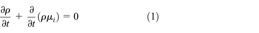


in which
Schematic diagram of reduced fins.

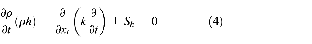
The equation governing the solid state is the heat conduction equation. Its general form is given as
The overall rate Q of heat transfer of the heat sink is defined as

in which

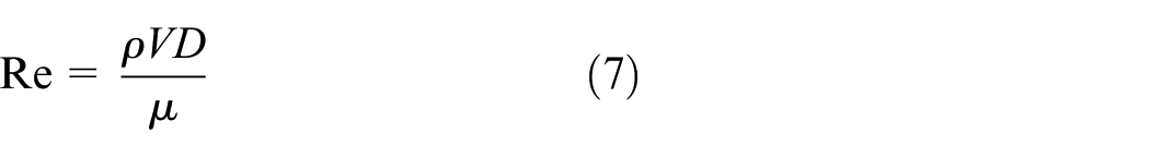
The Reynolds number is defined as
We treated the pressure term with a standard approach but solved the pressure–velocity coupling with the SIMPLE algorithm. The convergence criterion to terminate the computation was defined as 10−7 for the scaled residual of the energy equation or 10−5 for the scaled residual of other equations.
Meshing
In order to verify the accuracy of the calculation model and the numerical method, the grid independent verification was used. The numerical simulation heat sink was placed in the channel, and the two-step heat sink was verified by the Re = 5000. Since this study mainly discusses the effect of thermal resistance value, manual grid encryption is performed around the radiator, and the grid points are compared with the thermal resistance value independently. The results are shown in Figure 2. The thermal resistance values of the number of grids 60,190, 113,242, 201,151, 294,664, 385,953, 501,762, and 625,485 are 5.112725°C/W, 5.40662°C/W, 5.65369°C/W, 5.83492°C/W, 5.768825°C/W, 5.4887°C/W, and 5.543985°C/W. The number of grids 625,485 increased by 512,243 grids over 113,242, but the thermal resistance values differed by 0.8%. Therefore, in order to take into account the accuracy of the simulation and the time of the simulation operation, this study will take the number of grids 113,242 as the reference basis for grid construction.

Grid independence test.
Results and discussion
Figures 3 and 4 are velocity distribution diagrams when Re = 5000 and 40,000. Two-step fins: when Re = 5000, the gas does not enter the fins at all, the velocity field is very slow, and the gas flows directly along the steps to the rear end of the fins. However, as the Reynolds number increases, it is obvious that the gas has entered the fins. Three-step fins: when Re = 5000, part of the gas enters the fin, but it is also limited to the part along the step surface, and the flow of the two-step type gas is better, but the Reynolds number increases, the gas will enter the fins. After Re = 40,000, the range of gas entering the fins has also increased. However, the maximum speed occurs above the heat dissipation fins because the fluid resistance above the heat dissipation fins is small. When the gas hits the heat dissipation fins, it will flow upward along the fins, causing the gas velocity above the heat dissipation fins to increase.

Velocity distributions on the symmetric plane of a heat sink (Re = 5000).

Velocity distributions on the symmetric plane of a heat sink (Re = 40,000).
From Figure 5, it can be found that the overall temperature (Re = 5000) of the two-step and three-step is higher, and the two sides of the front end of the flat plate heat sink have a small part of lower temperature. From Figure 6, it can be found that in addition to the gradually increasing temperature diffusion range at the front end (Re = 40,000), the diffusion range increases to both sides of the rear end of the heat sink. The temperature spreads and the range gradually expands, effectively removing heat. Increasing the Reynolds number can effectively reduce the surface temperature of the heat sink.

Surface temperature of heat sink (Re = 5000).
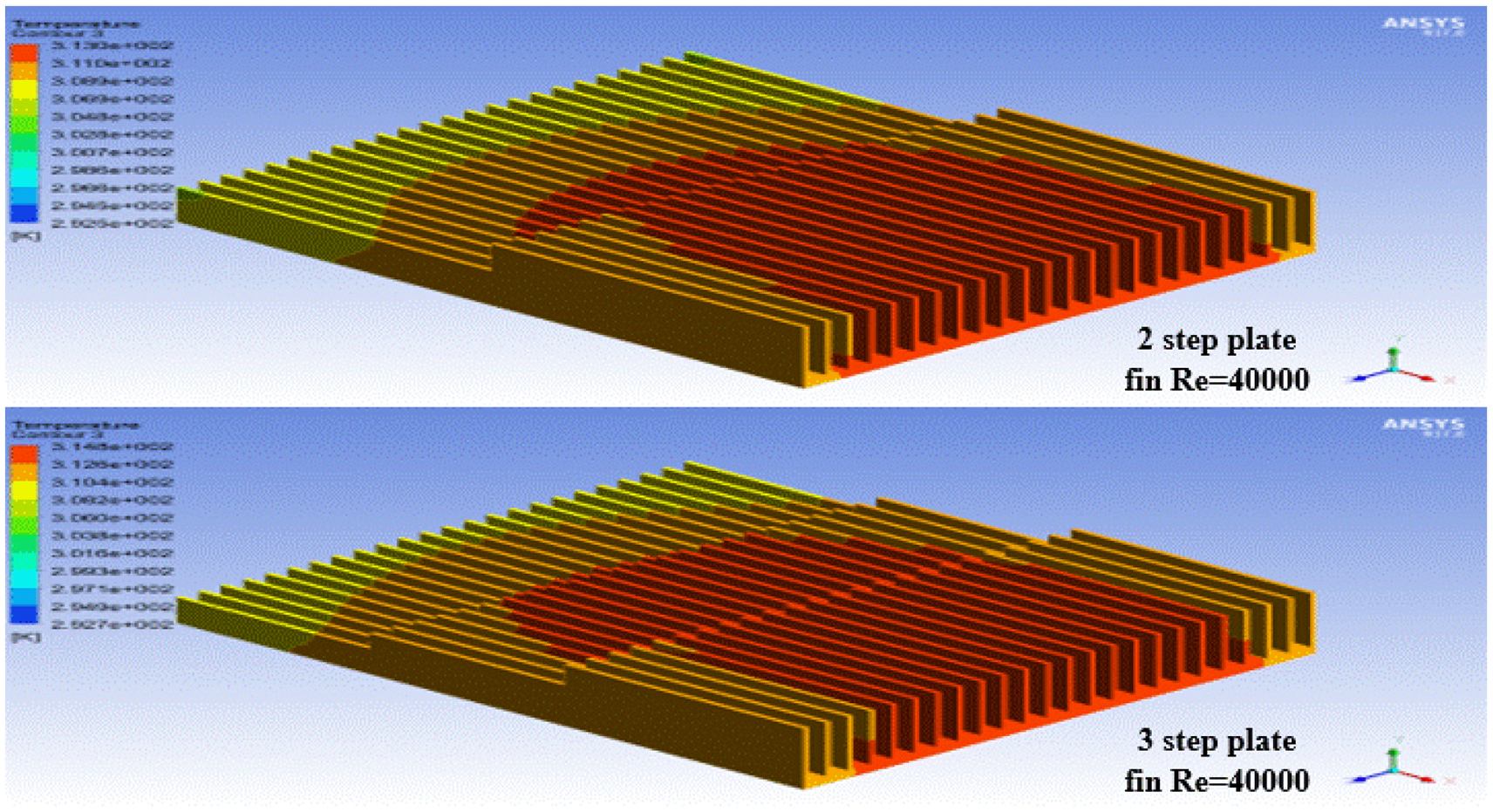
Surface temperature of heat sink (Re = 40,000).
From Figure 7, the change in thermal convection coefficient is very small at low wind speeds, and the wind speed gradually increases; as the forward wind speed increases, the heat convection coefficient also increases. With the increase of Reynolds number from Figure 8, the heat resistance has a significant decrease in thermal resistance, and the best overall thermal resistance performance is the flat type. In the two-step and three-step heat sinks, although the thermal impedance value is higher at Re = 5000, as the Reynolds number increases, the thermal impedance of the heat sink decreases significantly, and even at Re = 40,000, the thermal impedance is already close to flat plate heat sink. Although the heat transfer performance of the two-step and three-step types is not better than the flat type, the two-step and three-step types generally have good heat transfer performance at high Reynolds numbers, so the material is saved. Considering with mass production, it is to achieve cost savings.
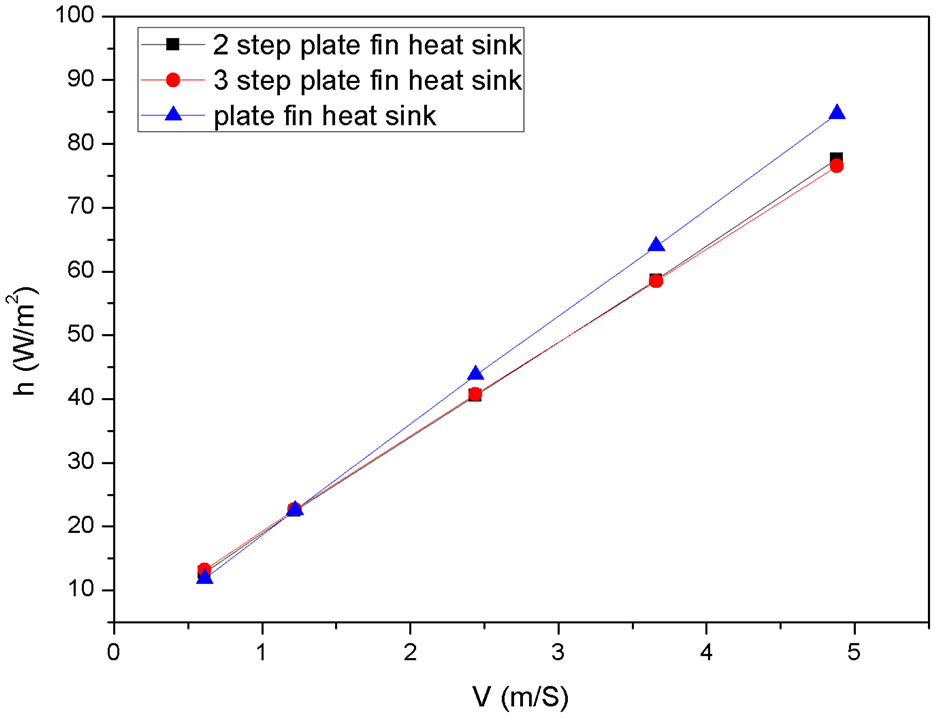
Convection heat transfer coefficient of heat sink.
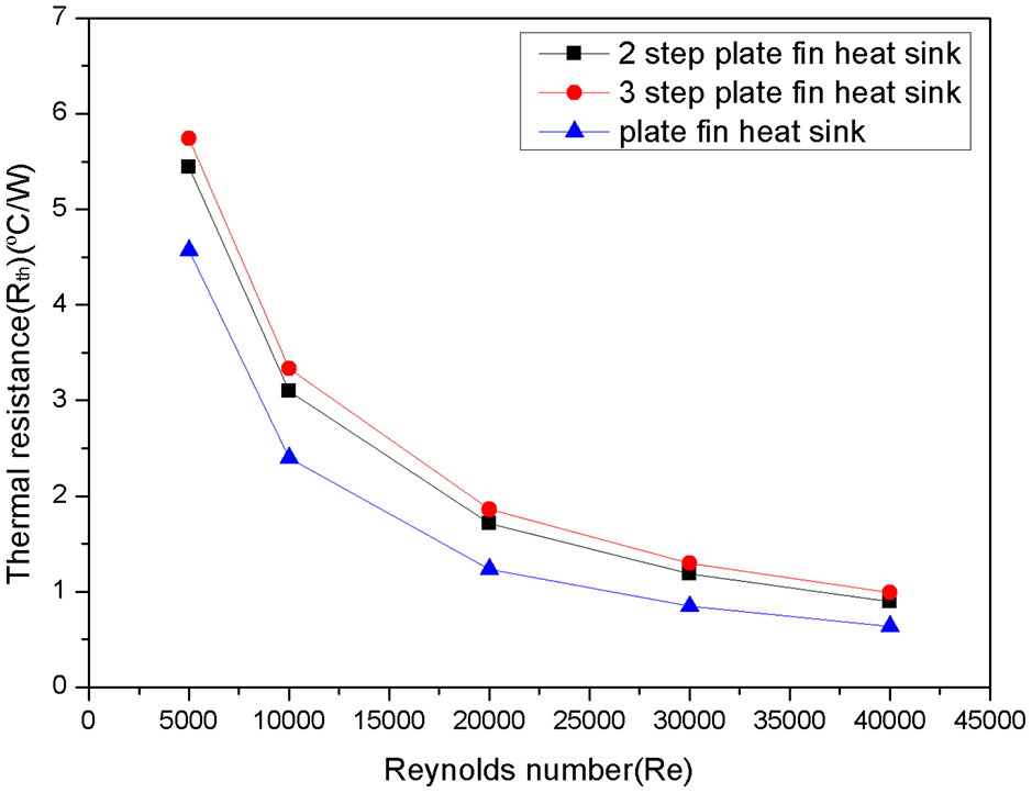
Reynolds number versus thermal resistance.
Conclusion
ANSYS Fluent software uses five different types of heat sinks to establish a channel for simulation analysis and comparison. Although the stepped heat sink has a reduced heat dissipation area, with the increase of the Reynolds number, the overall heat dissipation performance is not necessarily poor. With the increase of the Reynolds number to Re = 40,000, the overall heat transfer performance is better than the Pin heat sink. Increasing the Reynolds number is helpful to reduce the overall temperature and thermal resistance of the heat sink, but the increase in the Reynolds number gradually decreases the thermal resistance value. Therefore, increasing the Reynolds number is used to improve the heat transfer performance of the heat sink. There are limits. The design concept of material reduction has a significant impact on processing and cost. The results in this article show that the selection of an appropriate heat sink fin and a specific Reynolds number can effectively improve the heat transfer performance of the flat plate heat sink. When three grooves are added, although the surface area is reduced, the overall heat transfer performance is improved. Higher thermal convection coefficient, lower pressure drop and thermal resistance are the overall heat of the five heat sinks. The heat transfer performance is the best, so properly adding grooves on the appearance of the heat sink can help improve the overall heat transfer performance of the heat sink.
Footnotes
Handling Editor: James Baldwin
Declaration of conflicting interests
The author(s) declared no potential conflicts of interest with respect to the research, authorship, and/or publication of this article.
Funding
The author(s) received no financial support for the research, authorship, and/or publication of this article.