
Abstract
In this study, a numerical method was used to investigate the melting process of PCM-Heat Sink and PCM-Hybrid Heat sinks for electronic cooling. Firstly, three different PCMs, designated as RT-28HC, RT-31, and RT-54HC, with varying thermophysical properties, were used within aluminum finned heat sink and three-dimensional time-dependent analyses was conducted using the ANSYS Fluent software, at heat fluxes of 3.6, 4.2, and 4.8 kW/m2. To calculate the enhancement ratio in the PCM-Heat Sink, setpoint temperatures of 45°C and 60°C were selected. The results revealed that RT-54HC is the best option among them, since it produced the lowest heat sink base temperature at the end of 120 min simulation period. At last, two hybrid heat sink models, designated as HPCM1 and HPCM2 were designed and their cooling performances were analyzed at heat transfer coefficients of 5, 10, and 15 W/m K. The RT-54HC was used as the PCM for hybrid heat sinks at a heat flux of 4.8 kW/m2. It was observed that HPCM1, with heat conductivity coefficients of 10 and 15 W/m2 K were more effective than PCM-HS models for cooling. In conclusion, this study provides useful guidelines for designing heat sinks and selecting PCM types for electronic cooling.
Introduction
Excessive heat generation from electronic devices is a growing challenge with the introduction of more compact and higher performance devices. This leads to a deterioration in the operating performance and the service life of the electronic device. 1 Consequently, effective thermal management is crucially important in electronic devices. Phase-Changing-Materials (PCMs) are often considered to be effective components in cooling units. A PCM is capable of absorbing a large amount of heat energy at an almost constant phase change temperature. PCMs are also lightweight components and they require fewer equipment compared to traditional cooling systems. Therefore, a PCM-based heat sink is often preferred as a passive cooling method in thermal management of electronic devices. PCMs, as their name suggests, inherently have the ability to change phase. PCMs can absorb heat by transitioning from solid phase to liquid phase and release heat by transitioning from solid phase to liquid phase. They can offer a large thermal capacity with a certain temperature range. The latent heat and melting temperature range of each PCM is different. This significantly affects the melting process. The operating principle of PCM is quite simple. When the temperature increases, the PCM absorbs heat and its phase transitions from solid to liquid as an endothermic process. As a reverse process, when the temperature decreases, the PCM releases heat and its phase changes from liquid to solid as, an exothermic process. 2
In the melting process, heat is first transferred to the PCM by conduction, and then by natural convection. The reason is, the removal of the solid region from the heat transfer surface and increase in the thickness of the liquid region near the heat transfer surface. Since the thermal conductivity of a liquid PCM is lower than a solid PCM, the conduction of heat can be negligible while the melting of PCM. The biggest portion of heat transfer occurs by natural convection, due to the density gradient of liquid PCM in melting process of PCM. 3
PCMs are classified as organic, inorganic, and eutectic mixtures. For choosing the right PCM, attention should be paid to some criteria about the crucial parameters, such as a high coefficient of thermal conductivity, a high latent heat, a high specific heat, and a small expansion-contraction during the phase change. 4 In addition, it should be noted that, the melting temperature of the PCM should not be lower than the maximum operating temperature of the electronic device. 5 Among the PCMs, the organic, paraffin-based ones are very popular among researchers because they have a wide melting temperature range.
Although PCMs have high heat capacity, they also have a low thermal conductivity. This slows down the heat absorption and heat dissipation during melting and solidification. In many studies, embedding the PCM within a heat sink, which acts as a Thermal Conduction Enhancer (TCE), has been considered and evaluated. Embedding PCM in the heat sink can enhance the heat dissipation capability. Such systems are called “PCM Heat Sink.” Baby and Balaji 6 conducted an experimental study of a copper foam-PCM based heat sink and they found that the operational time increased by seven times with use of copper foam. At the power level of 2.4 W/m2, they observed a 24% reduction in the heat sink temperature. Huang et al. 7 conducted a numerical study using low melting point alloy (LPMA) and paraffin as PCM to reduce the weight and cost of the heat sink. They measured the effects of LPMA volume fraction, fin structure, and thermal power on the performance of dual PCM-heat sink. Their results showed that, due to the non-identical thermophysical properties of dual-PCM, although melting processes of the two PCMs were not simultaneous, their thermal performances were compatible in the phase change phase. A fin structure is often used in conjunction with a heat sink to expedite the heat transfer. Many studies in the literature investigate the effects of the fin structure’s dimensions and geometric properties on heat transfer. For example, Pakrouh et al. 8 conducted a numerical study for the PCM based pin fin heat sink. They examined the effects of parameters, such as heat sink base thickness, fin height, fin thickness, and number of fins. They pointed out that the number of fins has a significant effect on the heat removal performance of the heat sink. Arshad et al. 9 used a two-dimensional, time-dependent numerical simulation method to examine the heat transfer and flow field characteristics of PCM-based finned heat sink. They reported that when the fin thickness was 3 mm in finned heat sink, the melting time increased by 6.63%, 3.59%, and 1.90% for 4, 5, and 6 W power levels, respectively, compared to 2 mm fin thickness case. Elshaer et al. 10 numerically studied a PCM based heat sink for thermal management of satellite subsystems. They selected RT-35 as PCM. They used three different fin orientations with heat sink, such as parallel fins, cross fins, and pin fins. Their results showed that the triangular pin fins have better performance than others. With triangular pin fins, a maximum temperature of 41.5°C was observed, corresponding to a 10.8% reduction. Similarly, Elshaer et al. 11 also numerically investigated PCM-based heat sink for thermal management of satellite subsystems. For this study, they used cross-shaped, I-shaped, and V-shaped fins with heat sink. They also used RT-35 as PCM. Their findings showed that, the heat sink temperature was reduced by about 1.6%, 2.6%, and 6.6% than circular fin by using cross-shaped, I-shaped, and V-shaped, respectively. Furthermore the melting fraction of PCM increased about 32.3% by using V-shaped fins. Joshi and Rathod 12 have investigated the optimum fin size and location to increase PCM heat transfer. It is clear from the result that the fin design increased thermal performance by 4.38% compared to the conventional design. Halving the fin volume not only increased the thermal energy storage but also reduced the solid mass of the fins. This showed that halving the fin volume can help reduce the overall weight of thermal energy storage systems. Kalbasi et al. 13 studied the optimum number of fins in PCM-based heat sink and examined the relationship between the number of fins and fin spacing for various heat flux inputs. In their study, they investigated around 900 different geometries of heat sink at input heat fluxes of 5000 and 10,000 W, for finding optimal number of fins. The results showed that the optimal number of fins decreased when the fin thickness increased.
Zahid et al. 14 conducted an experimental study, in various heat sink as simple heat sink as a square pin-fins heat sink, and Cu foam integrated heat sink for passive cooling. They used nano enhanced PCM and selected alumina as enhancer. Different concentrated with 0.15, 0.20, and 0.25 were used in RT-54. The results showed that base temperature was reduced by 36.96% in Cu foam integrated heat sink. Chen et al. 15 experimentally and numerically studied a heat sink with rectangular fins that had paraffin as PCM, placed within a small cavity. They investigated the effect of the PCM heat sink on fluid flow and heat transfer characteristics, as well as the effect of the PCM heat sink height on heat transfer rate and heat absorption. The results indicated that 22.5% of the thermal energy could be absorbed by using PCM heat sink. Under the same conditions, with 0.012 m height of heat sink absorbs 14% heat than 0.02 m.
Heat sink fin structures may not always be uniform. In the recent years, tree-shaped fin structures started to be used. Xie et al., 16 placed PCM into a plate and tree-shaped finned heat sink and analyzed it under two different conditions, with and without taking natural convection into account. They observed that the thermal performance of PCM-based heat sink is positively affected by natural convective heat transfer. Mills et al. 17 also conducted an experimental and numerical study of melting process of PCM in a heat sink with a tree-shaped internal fin. The aluminum tree-shaped heat sink is formed with aluminum and bio-based coconut oil as PCM. In the study, the effect of orientation of the heater and the input power were investigated. The results showed that heater temperature dropped approximately by 17% and 23% when heating from the side and when heating from the bottom, respectively, compared to heating from the top, at heat flux of 7.3 W. Besides tree-shaped fins, a honeycomb heat sink design was studied by Ben Abdelmlek et al. 18 They studied thermal management of LED lamp by using honeycomb heat sink filled with PCM. Three different heat sinks, such as an aluminum-filled honeycomb radiator, a hollow honeycomb radiator without PCM, and a hollow honeycomb radiator with PCM, were numerically simulated. The results showed that a 25% temperature reduction occurred in the hollow honeycomb radiator with PCM for a 20 W power lamp.
The angle at which the fins are placed on the heat sink also affects the heat transfer rate. Thus, Ji et al., 19 carried out a numerical study, placing fins at +0°, +15°, +30°, −15°, and −30° angles for improving the non-uniform heat transfer of a vertically heated rectangular housing. They found that placing the fin at +15° angle increased the melting rate significantly, compared to a same length fin placed zero angle. This arrangement also reduced the melting time by 67.7%. Sunku Prasad et al. 20 developed a numerical model to study the behavior of a PCM-based heat sink for electronic cooling applications at constant and variable heat fluxes. They utilized two different PCMs for the analysis (RT-35HC and RT-44HC). The results showed that the base temperature of the PCM-based heat sink was lower under constant heat flux of 50 W/m2 K compared to it was at variable heat flux.
There are very few studies in the literature comparing different PCMs. One of such studies, which examined the thermal behaviors of different PCMs under natural convection conditions, was conducted by Ali et al. 21 In the study, the effect of PCM type on thermal performance of the PCM heat sink was investigated. The results showed that the heat sink performed better with n-eicosane than it did with paraffin wax. Irshad et al. 22 applied a numerical method by using PCM based heat sink with triangular and rectangular pin-fins. The analyses were performed by using three different PCM, such as RT-54, RT-44, and RT-35 HC, at input powers in the range between 4 and 8 W, in COMSOL Multiphysics 5.5. The results showed that triangular pin fins reached the maximum heat transfer rate with RT-35HC and RT-54, at 5 and 8 W, respectively. In addition, Soliman et al., 23 conducted an experimental study, using a PCM heat sink with a flat heat pipe, for thermal management of PV systems, to study the effects of different PCM’s with heat pipe. Three PCMs, designated as RT-25, RT-35, and RT-44, were used with heat pipe in the experimental study. Furthermore, usage of one or two heat sinks were compared to using only a PCM. The results indicated that RT25 attained the lowest PV temperature and RT44 had the highest energy storage.
Like the passive methods like PCM based Heat Sink, PCM-hybrid heat sink is another method for cooling. Various studies on PCM-Hybrid Heat Sinks were published. Sahoo et al. 24 experimentally investigated a PCM based Hybrid Heat sink for electronic equipment cooling. They used eicosane, hexadecanol, and paraffin as PCM, with two different heat sinks, designated as Heat sink I and Heat Sink-II. In another study, a hybrid heat sink model was numerically analyzed for different PCM materials. Kalbasi 25 studied a novel PCM based hybrid heat sink with air for thermal management of electronic devices. The results showed that thermal performance of hybrid heat sink was better than those of PCM based and air-cooled heat sinks. Furthermore, it was seen that a hybrid heat sink with a 50 W/m2 K convective coefficient could compete with an air-cooled heat sink with a 100 W/m2 K convective coefficient. Nandan et al. 26 experimentally investigated the thermal performance of a PCM based finned heat sink under passive and active convective conditions. They used paraffin wax and 1-hexadecanol as PCM. The power input, varied from 4 to 12 W, was applied on the heat sink with PCM and without PCM at constant and cycling loading. They reported that that using 1-hexadecanol with heat sink provided better thermal performance in transient operation and under active conditions, total process time of the heat sink was reduced by 41% and 43% than that in passive conditions, when Paraffin wax and 1-hexadecanol was used with heat sink, respectively.
There are also some studies in which hybrid heat sinks were used with heat pipes. For instance, Ali 27 conducted an experimental study using PCM hybrid heat sink with heat pipe. Different heat sink geometries were investigated with RT-64 as PCM. Results depicted that the base temperature was reduced by 38% and 39% with using hybrid system at heat fluxes of 2 and 3 kW/m2, respectively. In addition, there are other studies in which PCM- hybrid heat sink was combined with additional applications, like heat exchanger, multichannel, to improve the heat transfer rate. Boujelbene et al. 28 numerically investigated melting and solidification processes of PCM in horizontal double-tube heat exchangers integrated with straight and twisted fins. RT-35 was selected as the PCM that was placed in inner tube and water was selected as the heat transfer fluid, which was placed in outer tube. The results indicated that heat transport and phase change rates were better improved by twisted fins than straight fins. Furthermore, it was seen that charging and discharging rates were increased by 10% and 14% with the twisted fin. Zhang et al. 29 reported a novel PCM-hybrid heat sink with the active and passive convection for controlling temperatures of electronic devices which give shock heat fluxes. Furthermore, the energy efficiency of hybrid heat sink was investigated. The results indicated that the PCM-hybrid heat sink had better performance than the conventional one and with using a hybrid heat sink, the energy efficiency increased by approximately 83.3%. Similarly, Ramesh et al., 30 numerically investigated PCM based hybrid microchannel heat sinks (PCM based MCHS) by using six novel heat sink designs. They analyzed the thermal performances of six different PCM based MCHS models in ANSYS Fluent and compared them with the empty heat sink. They found the temperature uniformity coefficient and the thermal resistance as 15.26% and 7.3% lower than traditional heat sink, respectively.
Selection of PCM has a significant importance because of the every PCM has different thermal and physical properties. Latent heat of PCM is an important parameter that determines the heat absorption capacity of the PCM. Therefore, a proper combination of PCM thermophysical properties ensures optimum cooling. 31 To our best knowledge, there are very few studies in the literature that compare different PCMs within heat sinks and this study is presented to fill this gap. In this study, thermal behaviors of the PCMs with different thermophysical properties were investigated under different heat loads. The aim of the study is to determine the most appropriate PCM for given temperature ranges. RT-28HC, RT-31, and RT-54HC were used as PCMs in heat sink. PCMs under heat flux values of 3.6, 4.2, and 4.8 kW/m2 were numerically analyzed to determine their thermal behaviors. In addition, hybrid heat sink configurations, which have become very popular in recent years, were compared to PCM heat sinks. Two different hybrid heat sink models were designed and thermal analysis of both models were conducted numerically, at air flows with convective heat transfer coefficients of 5, 10, 15 W/m2 K. A time-dependent model based on the enthalpy-porosity method was selected to characterize the PCM melting behavior. Afterward, time-dependent temperature and solidification values were plotted for each analysis. In the PCM based heat sink (PCM-HS) design, it was assumed that heat transfer occurs by natural convection in the melting stage. On the other hand, in the hybrid-heat sink designs, it was assumed that air flow is applied to the heat sinks at certain convective heat transfer coefficients, resulting in forced convection. The temperature and melting charts were also plotted in ANSYS Fluent Software for all the designs.
Methods
Description of numerical mode
PCM based heat sink (PCM-HS)
In the numerical study, a PCM-based finned heat sink was modeled in 3-D. The symmetry of the design was used in the analysis to reduce computational loads as shown in Figure 1. In the literature, there are many studies that used square pin fin for PCM heat sink.32–34 Thus, square pin fins with dimensions of 2 × 2 × 20 mm were selected to be placed inside an aluminum block of dimensions 114 × 114 × 25 mm. The pin fin heat sink design was adapted from Arshad et al. 35 The total number of pin-fins was 225. Al-6061 was used as the pin fin and heat sink material.

Three-dimensional schematic diagram of the computational domain.
It was assumed that heat enters the heat sink through the base, which has a rectangular surface of 100 × 100 mm2, and it is transmitted to the PCM through the base and fins. This arrangement was chosen to prevent the heat sink temperature from exceeding the maximum permissible value. This goal was reached thanks to PCM’s melting and heat absorbing actions. RT-28HC, RT-31, and RT-54HC were selected as PCM.
Thermophysical properties of PCMs were read from Rubitherm’s data sheet. 36 The properties of the PCM and heat sink materials used in the analysis are listed in Table 1. The melting temperatures of the selected PCMs vary between 27°C and 54°C. RT-54HC has a higher melting temperature than RT-31 and RT-28HC have, whereas RT-28HC and RT-54HC have higher thermal capacities than RT-31 has.
Properties of PCMs and materials used in design.

Some assumptions that had been done for the numerical analysis are listed below:
The liquid was of Newtonian type and incompressible.
According to the Boussinessq approximation, the density of the molten PCM was constant except for the z-momentum equation.
Volume change of PCM was neglected during melting. Therefore, solid and liquid PCM densities were assumed to be equal.
The bottom surface of the heat sink, except for the side wall surfaces and the heat input surface, was insulated, and the heat input surface was exposed to a constant heat flux.
The upper surface of the heat sink was subjected to natural convective conditions.
Initially, the heat sink, fin, and PCM were at the same temperature.
In Figure 2, the PCM-HS design for the first part of the study is depicted.

Schematic diagram of the PCM-HS used in current study.
PCM based hybrid heat sink (HPCM)
The PCM based hybrid heat sink (HPCM) combined both passive and active cooling methods. In HPCMs, PCM material is placed among the fins and air flow was generated by a fan, effectively removing heat from the heat sink. In this study, two different HPCMs were designed, designated as HPCM-1 and HPCM-2, and the schematic drawings of the HPCM designs are given in Figures 2 and 3. Unlike PCM-HS, PCM did not completely fill the space between the fins. This allows the inner surfaces of the fins and the heat sink to be also in contact with the air flow.

Different configurations of HPCM’s investigated in current study.
Boundary and initial conditions
Initially, PCMs and aluminum heat sink were assumed to be at a temperature of 288 K as
Initial conditions:


1. Heat flux on heater:

2. Symmetry Boundary conditions at the side:


3. Natural convective boundary conditions at the top of the heat sink:
4. Adiabatic walls:


In HPCM designs, since there was air flow, the forced convection conditions at the boundary conditions was changed as in equations (9) and (10).
Forced convection boundary conditions for HPCM-1:

Forced convection boundary conditions for HPCM-2:

Governing equations
In the design, it was assumed that heat transfer in the heat sink and the fins occurs by convection. Equation (11) is the governing equation for convective heat transfer.

Here, S refers to the source term. PCM-HS was modeled in three dimensions and the air flow was assumed to be laminar in the simulation.
Enthalpy-porosity technique
Enthalpy-porosity is a technique that is used to model convective-diffusion controlled phase changes in ANSYS. 37 This technique is crucial for accurately modeling the foundations of the solidification and melting process.
The Continuity equation:

The momentum equation:
The Energy equation:
The enthalpy term used in the governing equations includes the latent heat and the specific heat values. The H given in equation (14) can be expressed as in equation (15).

The terms h and

On the other hand,

In equation (17), L refers to the latent heat of the PCM and

The mushy zone is the place where melting and solidification actually begin and continue, while latent heat is simultaneously being absorbed or released. Mushy zone is critical for latent heat storage. The enthalpy-porosity technique treats the mushy zone as a porous medium and sets the porosity in every cell equal to the liquid fraction in that cell. 38 In totally solidified regions, the porosity is equal to zero. As the porosity decreases, the momentum, hence the speed in the mushy zone, is expected to decrease. Since the velocity in the mushy zone changes due to phase change, it is necessary to add the source term S to the momentum equation. The formulation of S is given in equation (19). 19

In the PCM melting process, the liquid PCM flow is assumed to be laminar, unstable, and incompressible. While PCM transitions from solid to liquid, the volume change was neglected. The thermophysical properties of the PCM, such as thermal conductivity, viscosity, specific heat, were set constant in the simulation. After a sufficient amount of PCM liquefied, natural convection dominates the heat transfer process. The effect of natural convection was defined using the Boussinesq approximation, in which the density changes with the buoyancy force. This approach is given in equation (20).

In equation (20),
Numeric analysis
In this study, after the model had been designed in the ANSYS Workbench, the mesh structure was created. Patch Conforming Method was used to create the mesh structure. Attention was paid to keeping the Mesh skewness ratio below 0.96 for a high-quality mesh structure. ANSYS Fluent 19.1, a commercial software, was used to solve the governing equations, based on the finite volumes method. The SIMPLE algorithm for pressure-speed coupling and the PRESSURE based solver was also used for pressure correction equality. The momentum and energy equations were discretized by the second-order upwind scheme. The convergence criteria was set to 10−5 for the speed and continuity components and 10−8 for the energy components. Parallel solver option was activated, so four processes could be simultaneously run on each core of a 4-core GPU.
The numerical model was verified with respect to an experimental study, which had previously been conducted and published by Kothari et al. 39 In their study, an un-finned heat sink with nano-enhanced PCMs and pure PCM had been used, in a constant heat flux of 2.0 kW/m2, for thermal management of electronics. They had used Al2O3 as Nano-enhancer in different concentrations and paraffin wax as PCM. The un-finned heat sink with internal dimensions of 100 × 100 × 20 mm3 and a heater with 100 × 100 × 4 mm3 dimensions had been placed on heat sink.
PCM Based heat sink had been insulated with Acrylic glass to ensure adiabatic conditions. The numerical model was run for validation by using the pure PCM in the un-finned heat sink at the same boundary conditions and geometric parameters as their experimental study. The initial temperature of the heat sink base was taken as 30°C. Time dependent temperature distributions and melting fraction results produced by the numerical and experimental studies are given in Figures 4 and 5, respectively. The results clearly show that there is good agreement between each other.

Comparison of present numerical study results with experimental temperature data from Kothari et al. 39

Comparison of present numerical study results with experimental liquid fraction data from Kothari et al. 39
Goodness of the results’ fit was evaluated by the root mean square (R2), whose formula is given in equation (21). R2 values for the temperature distributions and melting fractions were calculated as 0.9826 and 0.9943, respectively. Therefore, it was concluded that, our numerical model was capable of accurately estimating the behavior of a real setup. 40

Another validation of the numerical model was done with respect to the experimental findings of a study that had been published by Zahid et al. 41 In their study, they had investigated the thermal performances of different heat sinks, such as simple heat sink, circular pin finned heat sink, and copper foam heat sink with nano enhanced PCM at varying heat fluxes. They had used RT-54HC as the PCM. The numerical model simulated the simple heat sink with PCM, at a 2.94 kW/m2 heat flux. The simple heat sink had had dimensions of 116 × 116 × 32 mm3, a 7.5 mm wall thickness and an inner cavity of dimensions 101 × 101 × 27 mm3. A silicon rubber plate heater, that had been placed above the heat sink, had dimensions of 101 × 101 × 1.2 mm3. The scatter plot for comparing the experimental results and the numerical results is given in Figure 6. Here, again, the goodness of agreement criterion was the root mean square (R2) and a R2 value of 0.9678 indicates that the numerical model was quite accurate.
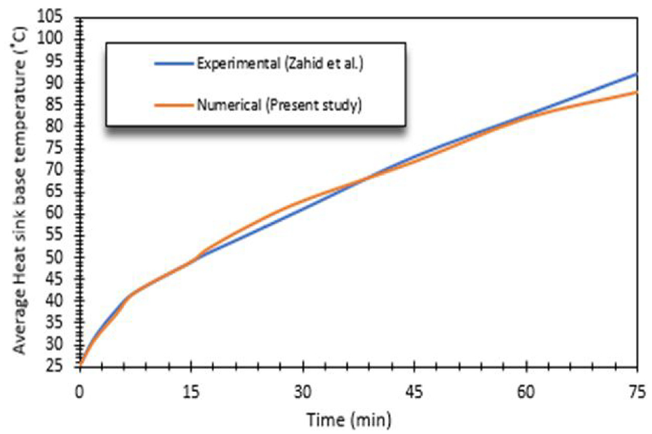
Comparison of present numerical study results with experimental study from Zahid et al. 41
For grid independency, three mesh structures were created with element sizes of 1, 1.5, and 2 mm. All the three numerical models with different mesh structures were run in the same boundary conditions and the results are also shown in Figure 7. It can be observed that, all the models produced very similar heat sink base temperature profiles. Accordingly, the mesh structures were created with a 1.5 mm element size. Furthermore, as time step can theoretically affect estimation of numerical results, three different time steps of 0.2, 0.5, and 1 s were used separately in the numerical analyses. However, the independence test showed no significant change in the heat sink base temperature with respect to the time step. This fact can be observed in Figure 8. Thus, the following numerical analyses were performed by taking time step sizes as 0.5 s.
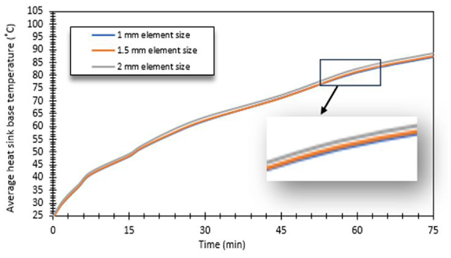
Grid independence study.

Temperature distribution of average heat sink base temperature for different time step size.
Results
PCM-HS
In the first part of the study, numerical analyses were conducted for PCM-HS. The thermal behaviors of three PCMs, each having different melting points and latent heats, were studied during melting process. RT-28HC, RT-31, and RT-54HC were selected as PCMs. Each PCM-HS was analyzed under different thermal power inputs. Figure 9 shows the change of three different PCMs’ base temperature with respect to time, under thermal power inputs of 3.6, 4.2, and 4.8 kW/m2.

The variation of three different heat sink base temperatures with respect to time.
The chart in Figure 9 shows that, for every PCM, when the heat power input increases, heat sink base temperature increases and PCM melting time decreases.
When a heat flux of 3.6 kW/m2 was applied to the system, the base temperatures of RT-28HC, RT-31, and RT-54HC reached 85°C, 122°C, and 59.4°C, respectively, at the end of 120 min. Similarly, under a heat flux of 4.2 kW/m2, the base temperatures of RT-28HC, RT-31, and RT-54HC were recorded as 107.9°C, 145°C, and 85.5°C, respectively. At a heat flux of 4.8 kW/m2, the base temperatures of RT-28HC, RT-31, and RT-54HC were read as 121.6°C, 169.6°C, and 112.49°C, respectively. In Figure 10, melting rates of three different PCMs with respect to time is given, at heat fluxes of 3.6, 4.2, and 4.8 kW/m2. The longest melting time at all heat fluxes was observed with RT-54HC. Two critical set point temperatures (SPT) were selected in the study. The first SPT was 45°C for the RT-31 and RT-28HC and the second SPT was 60°C for all the three PCMs.
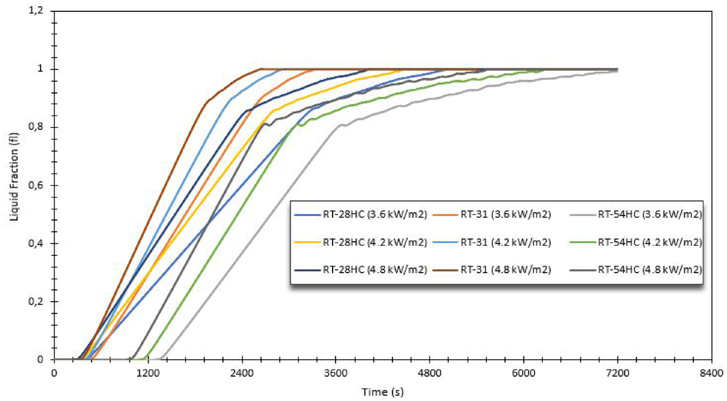
The variation of three different PCM melting process with respect to time.
In order to demonstrate the thermal performance of passive cooling, the Enhancement Ratio values, which report PCM melting rates, were computed. Enhancement Ratio (E.R.) is defined as the ratio of the time it takes to reach the critical S.P.T with a heat sink cooler to the time it takes to reach the critical S.P.T with PCM-based heat sink cooler. 42

In Figures 11 and 12, the E.R. values of PCMs were calculated for the SPT values of 45°C and 60°C at different input powers. Accordingly, it was observed that as the input power increases, the E.R. increases. E.R. values for RT-31 and HC were calculated as 8.6 and 13.8, respectively, for a critical SPT value of 45°C and at heat flux of 4.8 kW/m2. Since the melting point of RT-54HC was higher than 45°C, it was not included in the calculation of E.R. for SPT value of 45°C. Similarly, E.R. values of RT-31, RT-28HC, and RT-54HC were calculated as 6.74, 10, and 11.20, respectively, for a critical SPT value of 60°C and at heat flux of 4.8 kW/m2. For STP = 60°C, RT-54HC gave the best enhancement ratio. Based on this result, it can be concluded that, for electronic devices that have high operating temperatures, RT-54HC have the best thermal performance among the three PCM’s. For STP = 45°C, the enhancement ratio of RT-28HC was computed to be higher than that of RT-31. Thus, it can be reasoned that, for relatively lower temperature applications, RT-28HC is the more advantageous option compared to RT-31.

E.R. values of RT-31 and RT-28HC for the critical SPT point of 45°C.

E.R. values of different PCMs for the critical SPT value of 60°C.
Another important parameter is the Stefan number, which stands for the superheat gained from the PCM. 43 This dimensionless number was calculated as in equation (23). 44
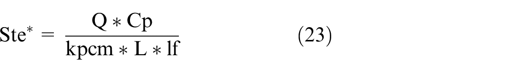
Table 2 shows the Stefan numbers for different PCMs and heat fluxes. If two PCMs have similar melting point temperatures to each other, their Stefan numbers melting times would also be similar.
Stefan numbers for different PCMs at various heat inputs.
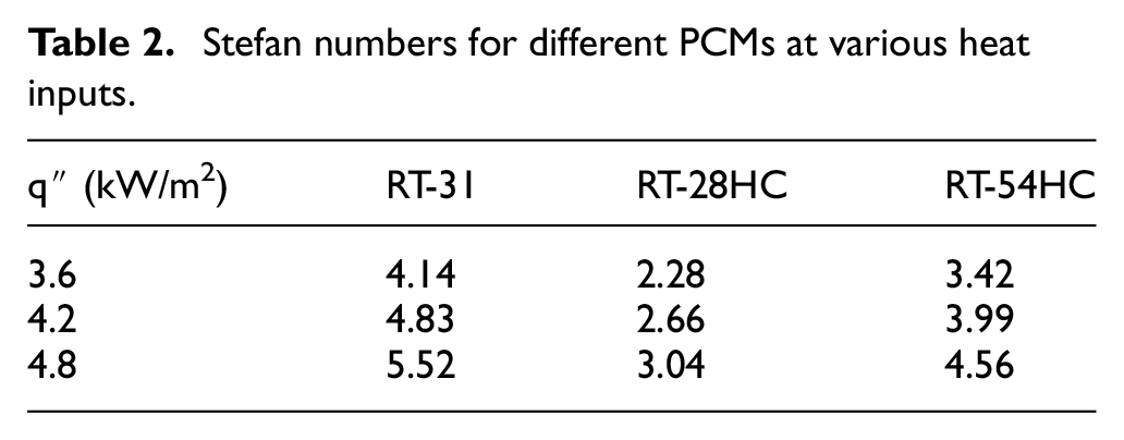
As the Stefan number increases, the time it takes to reach the critical SPT decreases. For a heat flux of 4.8 kW/m2, the melting times of RT-31 with a Stefan number of 5.52 and RT-28HC with Stefan number of 3.04 were 40 and 60 min, respectively.
Thus, it can be said that, for these two PCMs, which have low melting points, the melting time decreases as the Stefan number increases.
On the other hand, because the thermal conductive coefficient of RT-28HC is greater than that of RT-54HC, it can be concluded that the melting time of RT-54HC, which has a Stefan number of 4.56, is longer than RT-28HC.
Static temperature and liquid fraction contour charts were plotted in ANSYS Fluent to observe the changes in the melting rates and the heat sink base temperatures of the three different PCMs.
In Figure 13, the contour of temperature distribution of RT-28HC and in Figure 14, the contour of liquid fraction distribution of RT-28HC was given in times of 20, 40, 60, and 80 min for a heat flux of 4.8 kW/m2.
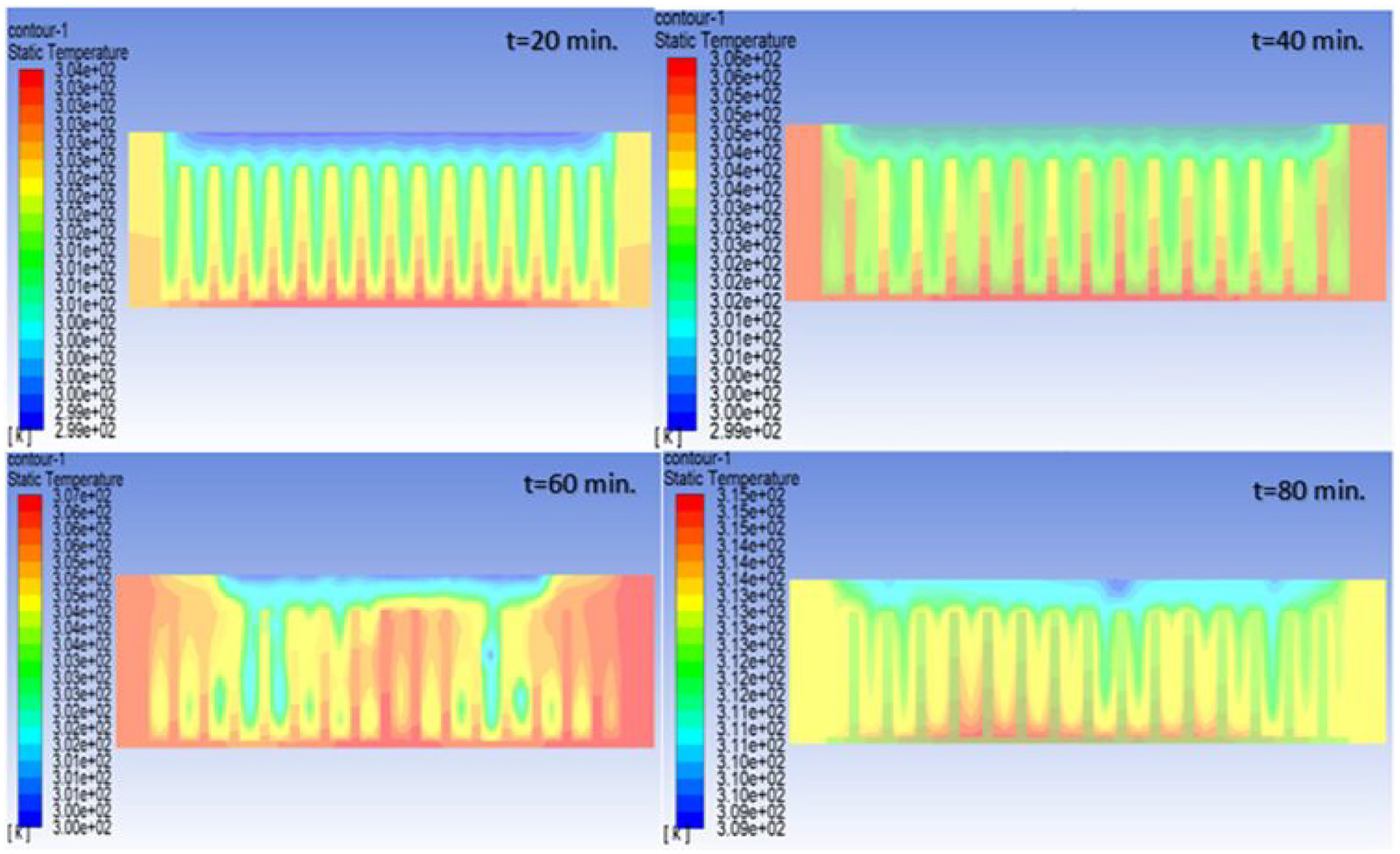
The contour of temperature distribution of RT-28HC.

The contour of liquid fraction distribution of RT-28HC.
Similarly, the contours of temperature and liquid fraction distributions of RT-31 and RT-54HC are given in Figures 15 to 18, for a heat flux of 4.8 kW/m2. While contours of temperature and liquid fraction distributions for RT-31 are given in times of 20, 30, 40, and 50 min, for RT-28HC, they are given in times of 30, 50, 70, 90 min, due to the longer melting times of PCMs.
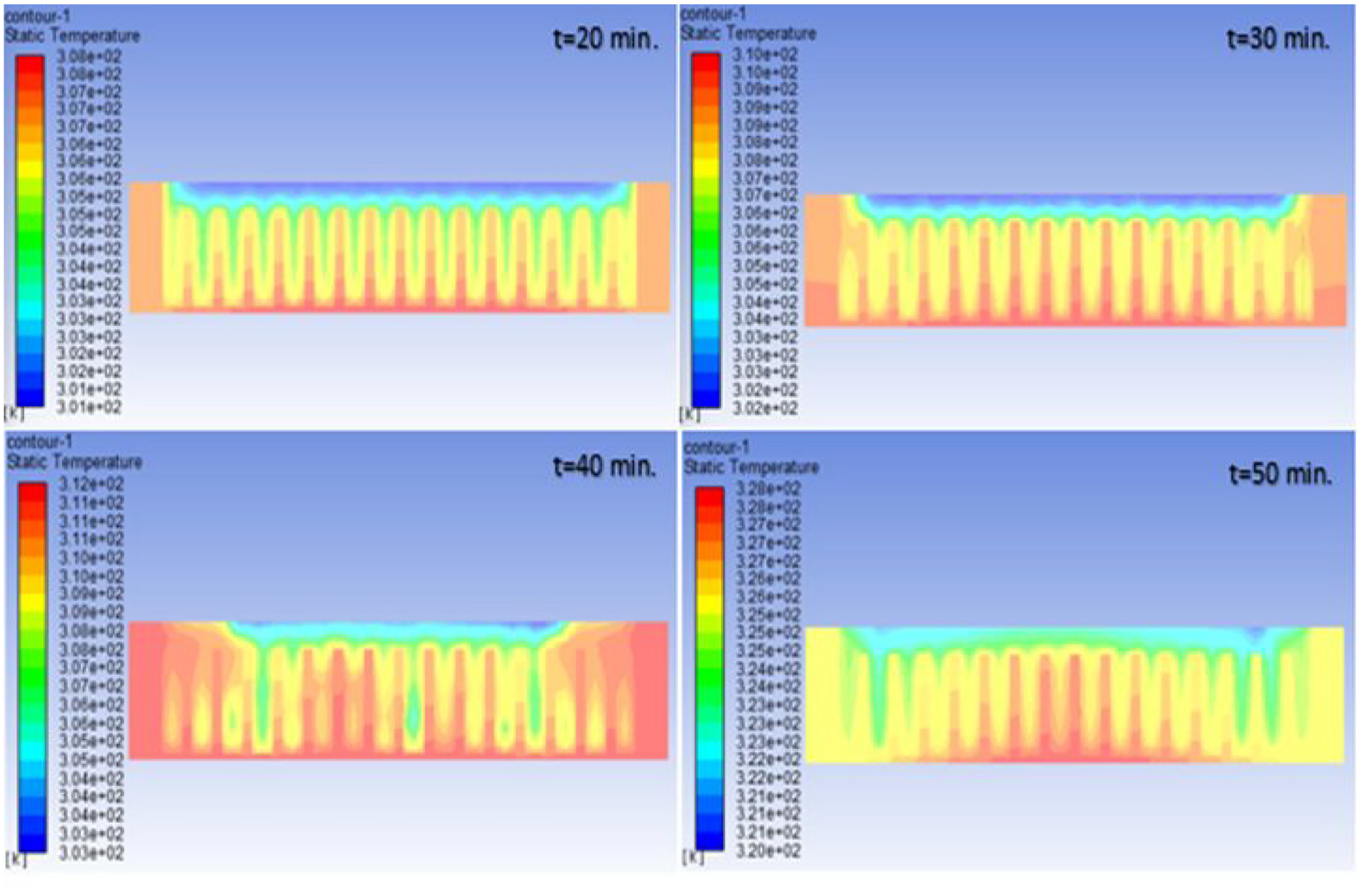
The contour of temperature distribution of RT-31.

The contour of liquid fraction distribution of RT-31.

The contour of temperature distribution of RT-54HC.
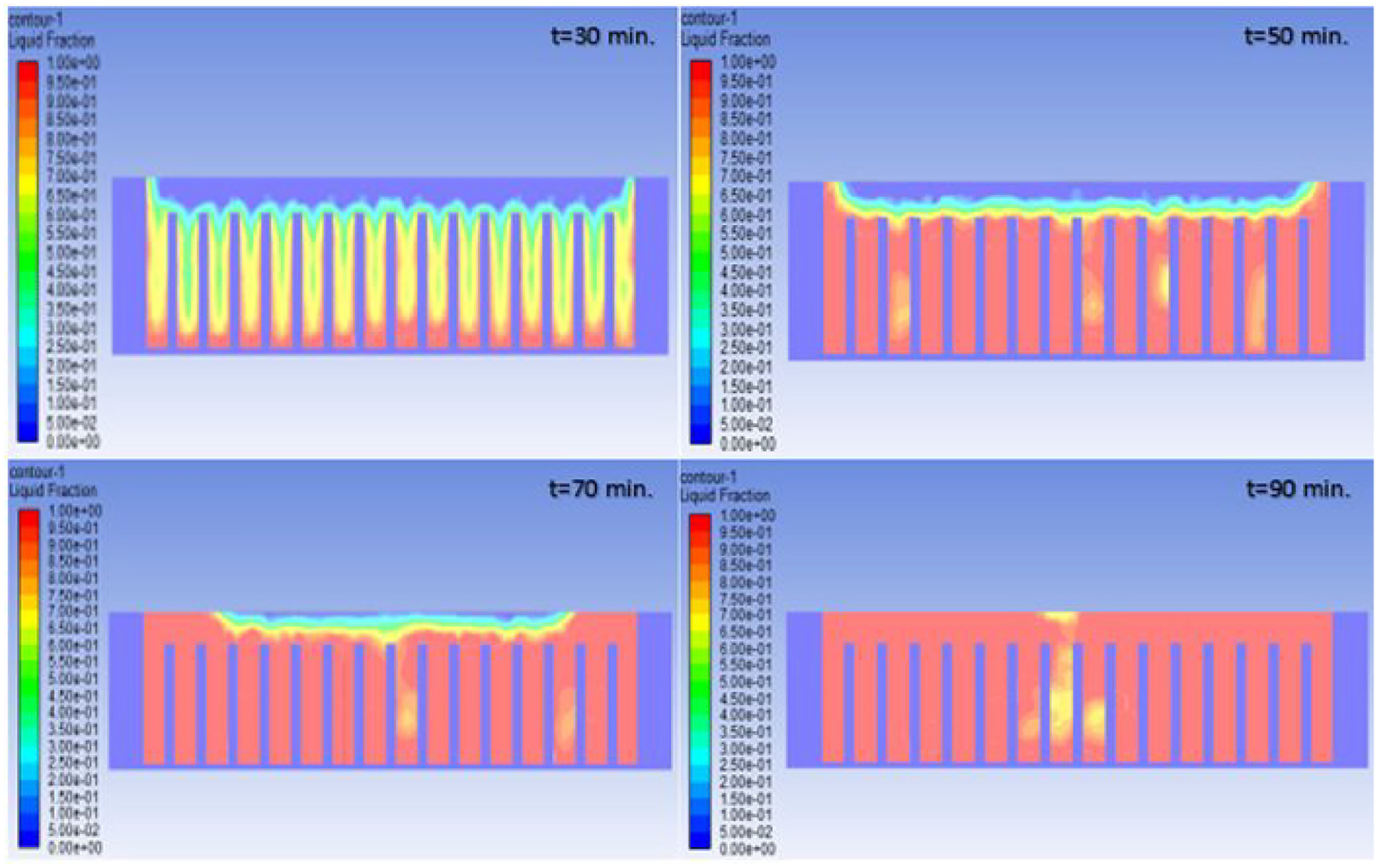
The contour of liquid fraction distribution of RT-54HC.
In Figures 13 and 18, there are different time intervals corresponding to the temperature distributions and liquid fractions for every PCM. While contour charts for up to 80 min are shown for RT-28HC, they are given up to 50 and 90 min for RT-31 and RT54HC, respectively. Moreover, every PCM started melting at a different temperature. The reason for this is, for every PCM, it takes a different duration to entirely complete the transition from the solid phase to the liquid phase. Also, every PCM has a different latent heat storage time.
Figures 13 and 14 illustrate the temperature distribution and the liquid fraction distributions of RT-28HC. It can be clearly seen that the melting rate at t = 40 min is significantly higher than that at t = 20 min. For RT-28HC, melting started at 302 K (29°C) temperature and completed at 307 K (34°C). So, it is observed that, melting rate increases with increasing temperature. In the time dependent temperature contour chart of RT-28HC, the lowest temperature of the PCM at t = 80 min is read as 309 K. This value is outside RT-28HC’s melting temperature range, which ends at 307 K. This can also be observed in the time dependent liquid fraction diagram and melting of the PCM is complete at the end of the related time window.
Figures 15 and 16 illustrate the temperature distribution and the liquid fraction distribution of RT-31, respectively. For RT-31, melting started at 300 K (27°C) temperature and completed at 302 K (29°C). Since the starting point of RT-31’s melting temperature range is similar to that of RT-28HC’s melting temperature range, the liquid fraction chart for this PCM is shown starting from t = 20 min. It can be observed that, at t = 30 min, melting rate of RT-31 is quite high and melting is entirely complete at t = 50 min. These plots reveal that, RT-31 melts faster than RT-28HC. At the first point where both PCM’s have totally melted, the maximum temperatures for RT- 28HC and RT-31 are 315 and 328 K, respectively. For now, it can be said that, among those two PCMs which have low melting points, RT-28HC is the more advantageous one.
The contours of temperature and liquid fraction distributions of RT-54HC are given in Figures 17 and 18, respectively. For RT-54HC, melting started at 326 K (53°C) temperature and completed at 327 K (54°C). The liquid fraction chart for RT-54HC starts from t = 30 min. Since RT-54HC has a high latent heat, like RT-28HC, the time it takes for it to completely melt reached almost 90 min. Within this time window, the peak temperature of the PCM with heat sink was recorded as 334 K (61°C). When comparing the temperature at the end of the melting stage, the heat sink with RT-54HC as the PCM exhibited the highest one. However, in terms of the average heat sink base temperature over the 120 min period, RT54HC, exhibited the lowest one over those three PCMs (112°C).
PCM based hybrid heat sink
In this study, not only PCM-HS was examined, but also two different PCM Based Hybrid Heat Sink (HPCM-1 and HPCM-2) models were considered at different heat conductivity coefficients for electronic cooling. RT-54HC was preferred as the PCM in the analyses, which were conducted with an heat flux was 4.8 kW/m2. In hybrid heat sink models, air was assumed to have the convective coefficients of 5, 10, and 15 W/m2 K and the analyses were run accordingly.
In Figure 19, the change of the heat sink base temperature with respect to time is given for each analysis.

Temperature distribution of different configurations for RT-54HC.
As can be seen in Figure 19, HPCM1 with convective coefficients of 10 and 15 W/m2 K, was better for thermal management than PCM-HS. But HPCM2, with convective coefficients of 5 and 10 W/m2 K, did not perform better than Pure PCM. HPCM2, with a convective coefficient of 15 W/m2 K, reached almost the same heat sink base temperature at the end of 120 min. In addition, between two hybrid heat sinks, the lowest heat sink base temperatures were obtained by using HPCM1 at all the three different convective coefficients. As a matter of fact, as the heat transfer coefficient increases, the average heat sink base temperature decreases. Furthermore, the lowest base temperature was obtained by HPCM2-15 in analyses. As a matter of course, as the heat transfer coefficient increases, the average heat sink base temperature decreases. Furthermore the lowest base temperature was obtained by HPCM2-15 in analyses.
Conclusions
In this study, numerical models were developed for PCM-based heat sink (PCM-HS) and PCM-based Hybrid Heat Sink (HPCMs) designs. In the first part of the study, the thermal behaviors of three different PCMs were examined at heat fluxes of 3.6, 4.2, and 4.8 kW/m2 and the results were compared to each other. RT-31, RT-28HC, and RT-54HC were selected as PCMs. Enthalpy-Porosity Technique was chosen for simulating the PCM melting process. The results were interpreted with the help of some parameters, such as Stefan Number and Enhancement Ratio.
The lowest Stefan number was obtained in RT-28-HC and the highest one was reached in RT-31. It was observed that, as the input power of system increases, the Stefan number of the PCM increases, for every PCM. It is also known that the melting time of PCM decreases as the Stefan number increases. Therefore, as the heat flux of system increases, the melting time of PCM is expected to decrease. For example, while transition from solid to fully liquid state of RT-28HC took 76 min with a heat flux of 3.6 kW/m2, this duration shrank to 70 and 64 min at heat fluxes of 4.2 and 4.8 kW/m2, respectively. The highest Stefan number reached was 4.14, by RT-31. In addition to this, Stefan number was calculated as 3.42 for RT-54HC and as 2.28 for RT-28HC. However, in this case, melting time did not decrease as the Stephan number of PCM increased. This can be attributed to higher thermal conductivity value of RT-28HC compared to that of RT-54HC.
When input heat fluxes of 3.6, 4.2, and 4.8 kW/m2 were applied to RT-28HC, RT31, and RT-54HC, it was observed that, for every 0.6 kW/m2 increment in input heat flux, the corresponding rises in the heat seat base temperature were 23°C, 24°C, and 27°C, respectively.
When an input heat flux of 3.6 kW/m2 was supplied to the heater, RT-31 started to melt at t = 412 s and transition from the solid phase to liquid phase was complete at t = 2614 s. Melting times of RT-54HC and RT-28HC were longer than RT-31 about 2.08 and 1.6 times, respectively, at same heat flux. For every PCM, an increased input heat flux resulted in an earlier start in melting. Similarly, total duration of melting also shrank. For example, total melting time of RT-28HC was reduced by 10.8% and 19.27% at heat fluxes of 4.2 and 4.8 kW/m2, respectively.
For every input power, the lowest heat sink base temperature was achieved with RT-54HC, thanks to its high melting temperature and high latent heat. The RT-54HC also had the highest E.R. value for the 60°C SPT point. For the SPT point of 45°C, which was calculated for RT-31 and R28HC (with a low melting point), highest E.R. value was obtained with RT-28HC in all input powers. For this reason, if it is necessary to choose a PCM with a low melting temperature, RT-28HC may be a good option with its fast melting rate.
In the second part of the study, two different HPCMs were designed and numerical analyses for these two models were conducted. RT-54HC was selected as the PCM in this part and all models were analyzed for a heat flux of 4.8 kW/m2. The analyses were repeated in different heat conductivity coefficients of 5, 10, 15 W/m2 K. Accordingly, it was observed that HPCM1, with heat conductivity coefficients of 10 and 15 W/m2 K, was more effective than PCM-HS for cooling. At the end of 120 min simulation period. PCM-HS had an average heat sink base temperature of 111.4°C. Under the same conditions, average heat sink temperature was reduced by 18.75% and 41% by using HPCM1, with 10 and 15 W/m2 K, respectively. Both HPCMs with heat conductivity coefficients of 5 W/m2 K did not provide better cooling than PCM-HS. HPCM2 with heat conductivity coefficients of 15 W/m2 K had almost the same average heat sink base temperature with PCM-HS at the end of the 120 min simulation time.
As a result, the lowest heat sink base temperature was obtained as 63°C with HPCM1 with a 15 W/m2 K heat flux within the 120 min simulation period and it was seen that the HPCM2 design was insufficient compared to PCM-HS, but HPCM1 was more effective than PCM-HS at air convection coefficients such as 10 and 15 W/m2 K.
Footnotes
Appendix
Handling Editor: Sharmili Pandian
Declaration of conflicting interests
The author(s) declared no potential conflicts of interest with respect to the research, authorship, and/or publication of this article.
Funding
The author(s) received no financial support for the research, authorship, and/or publication of this article.