
Abstract
In this article, the effects of film cooling holes arrangement and groove depth on the heat transfer and film cooling performance of blade tip are investigated. For this numerical research, a high-pressure turbine blade with the squealer tip is applied, and the tip clearance is given to be 0.8 mm (1% of the blade span). Simultaneously, a typical tip cooling technology of film holes in the groove floor is used. The number of film holes is fixed at 10, and two kinds of holes arrangements are considered: (1) equidistance distribution and (2) dense distribution near the leading edge. Three groove depths are studied with the values of 1.5, 2.0, and 2.5 mm (1.875%, 2.5%, and 3.125% of the blade span, respectively). The results show that the area-averaged film cooling effectiveness is higher when the holes distribute densely near the leading edge, and the cooling effect of the groove depth with 2.0 mm is obviously high compared with the other two depths.
Introduction
With the development of modern gas turbine technology, the inlet temperature in front of the high-pressure turbine is rising. Because the tip space is very small and the blade tip is over weak, the cooling for the blade tip is difficult. Meanwhile, the rotor blade tip would bear serious heat load due to the tip leakage flow erosion. Therefore, the study of approach in tip cooling and flow is eager to be implemented.
According to the researches, the most common cooling method for gas turbine blade tip is film cooling. The way of film cooling is achieved by one or more jetstreams blowing out from film holes, and the stream close to the hole forms a thin layer of cooling film and protects the tip wall from the high-temperature gas. It can provide efficient cooling characteristics. A solid summary can be found in the study of Bogard et al. 1 They pointed that film cooling performance is quantified by using the film effectiveness, heat transfer coefficients, and net heat flux reduction. Meanwhile, improving the thermal environment along the blade tip is generally accomplished through impingement cooling and film cooling. Researches have been done in blowing from the tip by Kim and Metzger, 2 Kim et al., 3 Kwak and Han,4,5 Ahnet al., 6 Christophel et al., 7 Acharya et al., 8 and Hohlfeld et al. 9
They also summarized the influence of cooling holes geometry and configuration. Huitao Yang et al. 10 performed numerical prediction of film cooling and heat transfer with different film holes arrangements on the plane and squealer tip of a gas turbine blade. They investigated three types of film holes arrangements and concluded that the film cooling effectiveness on the blade tip is higher. Chao Zhou et al. 11 studied thermal performance of cooled tips in a high-pressure turbine cascade. The calculations were performed using a cooled flat tip, a cooled cavity tip, and a cooled suction side squealer tip in a cascade at a tip gap of 1.6% blade chord. The results were presented in terms of heat transfer coefficient, cooling effectiveness, and so on. They concluded that the effect for the cooled suction side squealer tip was the best.
Meanwhile, studies of the tip leakage flow have been done, and there are many factors influencing tip leakage flow. In order to reduce the tip leakage flow, the squealer tip is a common mean. And the configuration of squealer tip has a great influence on the tip effect. Originally, Metzger et al.12,13 experimentally studied the cavity heat transfer on a transverse grooved wall in a narrow flow channel. It was also confirmed by the experimental results of the GE-E3 first-stage rotor blade tip with the flat and squealer structures at different boundary conditions which are concluded by the study of Bunker 14 and Azad et al.15,16 The effects of the turbulence intensity, the tip clearance size, and tip geometry on heat transfer characteristics were all investigated in their experiments. The results showed that the heat transfer distribution in the squealer tip is obviously different from the one with the flat tip.
However, it is difficult to measure the tip leakage flow and heat transfer in the tip gap and groove. In order to obtain an optimal cooling approach, it is necessary to know about the complex leakage flow of this region. Therefore, numerical simulation has played a more important role in the studies of tip leakage flow and heat transfer. And with the development of the computer technology and computational fluid dynamics (CFD), various types of the squealer tip configurations which investigators could envisage have taken less time and energy in studying. Ameri et al. 17 used numerical simulation to compare flat tip and squealer tip geometry. A variety of single- and double-side squealers were investigated in a rotating turbine by Camci et al. 18
Huitao Yang et al.19–21 performed numerical simulation of flow and heat transfer through a turbine blade with various tip configurations. They found that the squealer cavity leads to a substantial reduction in the heat transfer coefficient and leakage vortex than that of the flat tip. Meanwhile, Dianliang Yang et al. 22 conducted the numerical investigations by using the GE-E3 first-stage rotor blade with different tip gap height and groove depth. They indicated that the flow structure and the heat transfer distribution in the linear blade were different from that of the rotating blade. This was also investigated by the studies of Jiangtao Bai et al.,23,24 Maosheng Niu et al., 25 and so on.26–27
According to these studies, it is concluded that many geometric and aerodynamic parameters can reflect the blade tip heat transfer and flow characteristics. The different geometries and arrangements of film cooling holes have a great influence on the blade tip. It is essential to research the characteristic of the tip shape which can be thought. And the squealer tip is a labyrinth seal structure that increases the flow resistance and introduces additional resistance to the tip leakage flow path, which has an effect of reducing the tip leakage flow.28–34 A few studies about the influence of the groove depth are carried out. From the above discussion, the consideration of the tip groove depth is necessary.
The goal of this work is to present the tip cooling influence of different tip film cooling holes arrangements and groove depths. Because the temperature in the tip leading region is relatively high, two film holes arrangements of equidistance distribution and dense distribution near the leading edge are investigated. It can be noted that the previous numerical studies commonly adopt a partial blade, so a whole blade is researched in this article for getting a more reasonable result. By the numerical analysis, an optimal tip configuration is achieved.
Geometry models
To investigate the film cooling holes arrangement and squealer tip depth effect on blade tip, a high-pressure turbine rotor is used in this study. Figure 1(a) shows the cooling blade and flow information. The blade span is 80.0 mm and the tip clearance is 0.8 mm (1% of the blade span). The blade is cooled by two internal cooling passages and some cylinders near the trailing edge. Figure 1(b) shows the blade tip schematic diagram. It is a squealer tip. The depth of the squealer tip is 2.0 mm. The rim width on the pressure and suction side is 0.5 mm. The thickness of blade tip is 0.1 mm. There are 10 film cooling holes distributed in the middle line of the tip gap. The 10 film holes have an equal diameter of 0.5 mm. Meanwhile, the inner cooling passage is shown in Figure 2. The whole passage consists of two parts. The first part is a typical serpentine ribbed passage, and the second part, the trailing edge, is commonly cooled by pin-fin structure.

High-pressure turbine rotor sketch: (a) blade and gas flow and (b) squealer tip.

The inner cooling passage.
First, two kinds of film holes arrangements are considered, which includes equidistance distribution (Figure 3(a)) and dense distribution near the leading edge (Figure 3(b)). The film holes are distributed in the middle line of the blade tip. The squealer tip depths are 2.0 mm. Then, three squealer tip depths are studied with the values of 1.5, 2.0, and 2.5 mm, and the holes arrangement is equidistance distribution. The film holes are cylindrical and perpendicular to the blade tip. They have an equal diameter of 0.5 mm.

Two kinds of film holes arrangements: (a) equidistance distribution and (b) dense distribution near the leading edge.
Computational details
Overview
With the development of CFD, heat flow and solid coupling analysis can predict the flow and heat transfer characteristics of the blade tip well. The boundary conditions and grid independence study are presented in this part. The computational model is generated by UG version 8.0. The grids are acquired by a commercial software ICEM version 14.0. Figure 3 shows the computational grid of the high-pressure turbine rotor. The simulation software is CFX version 14.0.
Turbulence model
The numerical investigations in this article have been performed using commercial CFD software ANSYS CFX version 14.0. It has many kinds of turbulence models for CFD simulation, and different turbulence models employ different equations. According to the study of Huitao Yang et al., 19 the standard k–ε turbulence model and the scalable wall function are selected in this computational analysis. In the simulation of near-wall grid, it can improve the convergence and accuracy. The solid model of solid domain is defined to be thermal energy, which takes the influence of temperature on the blade into consideration.
Boundary conditions
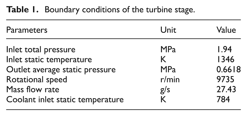
In this study, the boundary conditions are shown in Table 1. The blade rotational speed is 9735 r/min. At the inlet, the total pressure is 1.94 MPa, and the static temperature is 1346 K. The inlet flow angle is 59.47°, and the inlet turbulence intensity is 5%. The average static pressure is 0.6618 MPa at the outlet. The coolant inlet static temperature is 784 K. An adiabatic boundary condition is applied on the blade root and shroud surface. In the calculations, high first-order turbulence numeric method is selected. Convergent solutions are reached while the residuals are less than 1 × 10⁻⁴.
Boundary conditions of the turbine stage.
Grid independence study
In this study, both the aerodynamic and thermal performances are investigated numerically for different blade tip configurations. The grids of solid and fluid domain are meshed separately. At this time, the grids’ consistency of two domains’ interfaces should be kept. Because the computational models are complex, the unstructured grid is selected.
In order to improve the accuracy of calculation results, the grids of blade tip and film cooling holes are meshed, respectively (Figure 4). The y-plus values in the tip region are at the range of 30–100, and it can get an accurate result according to the study of Kuahai Yu et al. 35 Meanwhile, the y-plus values at the range of 30–300 are reliable in the standard wall function.

Schematic of the grid: (a) the whole blade and (b) the tip and holes.
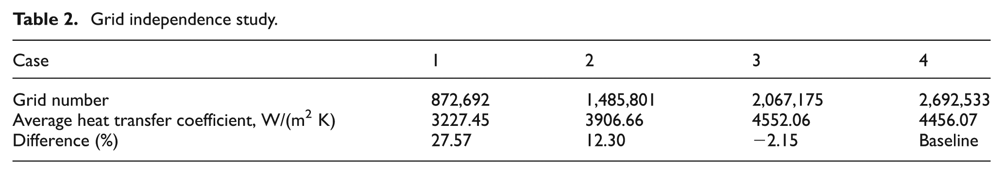
Generally speaking, the larger grid number is in favor of the calculation accuracy in the numerical study. However, it takes more time to compute the model with a larger quantity of grids. In order to keep a balance between computational precision and efficiency, four grid number systems (Cases 1, 2, 3, and 4) are discussed (Table 2). According to the study of Jin Wang et al., 34 the goal of grid research is the average heat transfer coefficient for blade tip. It has been evidently found that the average heat transfer coefficient difference in Case 3 is the smallest, and it saves computational time about one time than the Case 4. Therefore, the grid element number of 2,067,175 is selected finally.
Grid independence study.
Results and discussion
This section mainly describes the blade tip flow and heat transfer characteristics. The detailed numerical results are exhibited and discussed for different blade tip configurations.
Parameter definitions
In terms of the thermal performance for the blade tip, the parameters of heat transfer coefficient and film cooling effectiveness are generally analyzed in the past study. The definitions are given as follows.
The heat transfer coefficient is computed as
Here, q is the local heat flux per unit area, Taw is the adiabatic wall temperature, and Tw is the wall temperature.
The film cooling effectiveness is defined as

where Tm is the temperature of the inlet flow, Tc is the temperature of the coolant, and Taw is the adiabatic wall temperature. Higher film cooling effectiveness indicates better thermal protection by the coolant.
In order to achieve better analysis of the computational results, the average heat transfer coefficient and film cooling effectiveness of the blade tip are computed in this article. Finally, the thermal performance of the different blade tip configurations is evaluated.
Tip leakage flow characteristics
It has been studied that there is tip leakage flow on the squealer tip, which is caused by the different pressure between pressure side and suction side of the blade. Tip leakage vortex has a great influence on the blade tip flow and secondary flow. Therefore, the blade tip flow is investigated in this section. Figures 5 and 6 show the flow path lines on the tip zone of different film cooling holes arrangements and tip gap depth, respectively. The tip leakage vortex near the suction side of blade trailing edge and in the tip clearance is obviously observed. Meanwhile, the cooling air from the film holes flows along the groove wall of the blade tip, which has an effect on protecting the blade against the high-temperature turbine gas. Moreover, the tip leakage vortex in the tip clearance increases the flow resistance, which reduces the mainflow gas leakage of the blade tip. This study verifies that the average Mach number of the blade tip with film cooling holes structure is lower than that of the blade tip without holes.

The tip flow path of different film cooling holes arrangements: (a) equidistance distribution and (b) dense distribution near the leading edge.

The tip streamlines of different tip gap depths: (a) 1.5 mm, (b) 2.0 mm, and (c) 2.5 mm.
Figure 5 is the tip flow paths of different film cooling holes arrangements. The tip flow path of the tip holes with equidistance distribution is clearly shown in Figure 5(a), and the tip flow path of the tip holes with dense distribution near the leading edge is presented in Figure 5(b). Compared to Figure 5(a), the tip cooling flow volume near the leading edge is larger (Figure 5(b)), which leads to the more complex flow near the tip leading edge. From the numerical calculation results, we can find that the static pressure ratio between the pressure side and suction side (Table 3) is larger when the film cooling holes arrangement is dense distribution near the leading edge. It indicates that the dense distribution near the leading edge of the tip holes has an effect on reducing the tip leakage loss because of the stronger flow resistance.
The static pressure ratio of two different film holes distributions.
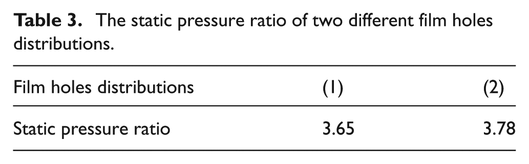
Figure 6 shows the tip streamlines of different tip gap depths. The depth values of 1.5, 2.0, and 2.5 mm which are 1.875%, 2.5%, and 3.125% of the blade span are, respectively, shown in Figure 6(a)–(c). The comparison indicates that the flow velocity is the largest and the cooling flow from the film holes can optimally attach to the groove floor when the gap depth is 2.0 mm. The effect of preventing the tip leakage is inferior with the smaller gap depth. When the gap depth is 2.5 mm, the pneumatic loss increases rapidly, and the turbine efficiency decreases. It is because the increase in groove depth inevitably leads to a more complex groove flow. Meanwhile, the blade tip static pressure ratio of different groove depths is listed in Table 4. According to the study of Dianliang Yang et al., 22 the larger static pressure ratio illustrates the better effect of throttling. Therefore, the blade tip with a 2.0-mm groove depth can reduce the tip leakage effectively.
The static pressure ratio of different groove depths.

Heat transfer
Figure 7 shows the tip heat transfer contour of two different film holes distributions. It demonstrates that the heat transfer distribution is of consistency between equidistance distribution and dense distribution near the leading edge. Because the mainflow gas temperature is the highest in the tip leading edge, the temperature difference between the mainflow gas and the tip leading edge is so severe that the heat transfer carries out easily. It is also found that the heat transfer coefficient decreases by the blade tip leading edge to the trailing edge. As the gas and cooling air is mixing and the cooling air is protecting the blade tip from the turbine gas, the touch between gas and the blade tip is more and more difficult from the tip leading edge to the trailing edge which also results in the lower heat transfer coefficient of the tip trailing edge. Meanwhile, the wall heat transfer of film holes is obviously higher than its surroundings as shown in Figure 7. Due to the tip cooling air obstacle during the leakage vortex through the film holes, the leakage flow is accelerated and the heat transfer increases partly between the two film holes. In addition, it is clearly shown that high heat transfer region after half of the blade tip moves from the pressure side to the suction side. Owing to the separated vortex caused by the leakage flow into the gap, the high-temperature leakage lifts up from the pressure side and the separation zone is formed. The leakage flow attaches to the surface of blade tip again through the separation zone. It directly leads to the rise in heat transfer around the suction side.
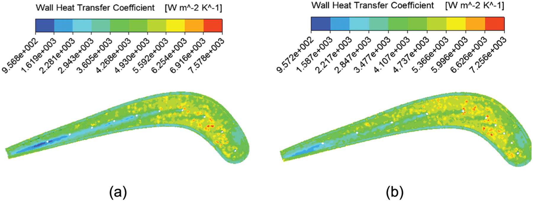
The tip heat transfer contour of two different film holes distributions: (a) equidistance distribution and (b) dense distribution near the leading edge.
Compared to Figure 7(a), the low heat transfer coefficient zone near the tip trailing edge is smaller (Figure 7(b)). With the film holes of dense distribution near the leading edge, the cooling air in the leading edge in pace with high-temperature gas flows through the tip gap to the blade suction side and the smaller amount of cooling air reaches the trailing edge. Accordingly, the tip cooling effect is balanced when the film holes arrangement is dense distribution near the leading edge and the average heat transfer coefficient is lower in this case. As is known to all, the high heat transfer coefficient causes the heavy heat load on the blade tip and the serious erosion. The balanced heat transfer means equal heat erosion. In this case, the working life of the blade tip can be extended. Overall, the effect of the tip holes dense distribution near the leading edge is better than the equidistance distribution.
The numerical results of the tip heat transfer coefficients with different groove depths are shown in Table 5. With the increase in groove depth, the tip average heat transfer coefficient gradually decreases which indicates that the blade tip is notably protected by the cooling air. However, the increase in groove depth results in the amount of high-temperature gas rising correspondingly. And it inevitably leads to the complex mixture flow between the cooling air from film holes and the gap mainflow gas. Combined with the tip heat transfer and flow characteristic, the effect of the blade tip with 2.0-mm groove depth is the best.
Average heat transfer coefficient of different groove depths.

Film cooling effectiveness
According to the study, the cooling effectiveness of the blade tip depends on the convection and diffusion of cooling gas. Figure 8 shows the tip cooling effectiveness of two different film holes distribution. It is clearly found that the film cooling effectiveness of the pressure side is lower than the suction side. Due to the blade rotation and the mainflow impacted, the cooling air from film holes shifts to the tip suction side. Meanwhile, the film cooling effectiveness around the film holes is higher than other areas. Because of the cooling air flowing with the mainflow, the cooling effect of the holes downstream is better than that of the holes downstream.

The tip film cooling effectiveness of two different film holes distributions: (a) equidistance distribution and (b) dense distribution near the leading edge.
Compared to Figure 8(a), the area of low film cooling effectiveness in the leading edge is larger (Figure 8(b)). When the film holes are arranged by dense distribution near the leading edge, a larger amount of cooling air exists. Simultaneously, the distribution of film cooling effectiveness is equal in Figure 8(b). In accordance with the previous conclusion of heat transfer coefficient, the cooling effect of film holes with dense distribution near the leading edge is better.
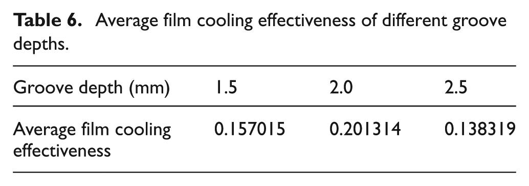
Table 6 is the average film cooling effectiveness of different groove depths. The comparison shows that the average film cooling effectiveness is the biggest when the groove depth is 2.0 mm, which is 28.2% bigger than that of the 1.5 mm groove depth and 45.5% bigger than that of the 2.5 mm groove depth. This result also proves the previous conclusion that the effect of the blade tip with 2.0-mm groove depth is the best.
Average film cooling effectiveness of different groove depths.
Conclusion
To investigate the heat transfer of different blade tip shapes, two kinds of holes arrangements and three squealer tip depths are considered. The holes arrangements are equidistance distribution and dense distribution near the leading edge, and three values of the groove depth are 1.5, 2.0, and 2.5 mm, respectively. Based on the above numerical analysis and results, the major conclusions are summarized as follows:
With dense distribution near the leading edge of the tip holes, the tip average heat transfer coefficient is lower. And the cooling effect of the whole blade tip is balanced. It is important to extend the working life of the blade. In a word, the effect of the holes arrangement with dense distribution near the leading edge is better.
With the increase in tip groove depth, the average heat transfer coefficient gradually decreases, and the average film cooling effectiveness increases first and then decreases. When the tip groove depth is defined to be 2.0 mm, the average film cooling effectiveness is the greatest obviously. Through integrating the heat transfer and cooling results into account, the effect of the blade tip with 2.0 mm groove depth is the best.
Footnotes
Declaration of conflicting interests
The authors declare that there is no conflict of interests regarding the publication of this article.
Funding
This work was supported by Graduate Starting Seed Fund of Northwestern Polytechnical University (Grant No. Z2014121), National Natural Science Foundation of China (Grant No. 51205315, 51375387 and 51210008), China Postdoctoral Science Foundation (2014M562281), Aerospace Technology Support Foundation (2014-HT-XGD), Science Foundation of Aeronautics of China (Grant No. 2012ZB53012), and Fundamental Research Foundation of NPU (Grant Nos JCY20130126 and 13GH014610).