
Abstract
GH536 has been widely employed as one kind of high-performance materials; however, the poor machinability of GH536 especially substantial tool wear can still be considered as a problem. On the contrary, deep cryogenic treatment can be considered as an effective heat treatment to improve the milling cutter performances. Considering few studies that investigated the deep cryogenic treatment of the WC-Co cutters, this article experimentally investigated the effects of deep cryogenic treatment on WC-Co cutter performances in milling of superalloy GH536. The detailed discussion in terms of the microhardness before milling, the cutting forces during milling, and the tool wear and the machined surface quality after milling operation were performed based on the in-depth analysis of the experimental result comparison between the deep cryogenic treatment and the conventional tools. Some key findings were given in the end to conclude this work.
Introduction
GH536 has been widely employed as one kind of high-performance materials in many industries, including aerospace, automotive, and energy due to the high hardness and the good strength. Although the new tools 1 and key knowledge of the process physics 2 in the precision machining have been highly developed, the rough machining process of GH536 can still easily result in hardening layers and significant tool wear or even burns.3–5 On the contrary, deep cryogenic treatment (DCT) can be considered as a special heat treatment method during which the specimen is cooled down or heat up at low temperature.1,2 DCT can result in the desired variance of material microstructures, and the typical variance can be the phase transformation between martensite and austenite, and the homogenization of carbide component distributions,3–5 highly improving the mechanical properties of specimens in terms of wear resistance, hardness, and fatigue life.6,7 Therefore, substantial efforts have been paid so far relating with the DCT, and many improved performances have been evidenced in the literature in terms of (1) tool hardness, (2) wear resistance, and (3) residual stress uniformity.
In terms of tool hardness, Akhbarizadeh et al. 6 found that the tool hardness after the DCT was improved by 8% in comparison with the original value, which can be related with the reduction of the retained austenite in the microstructure and the generated martensite with higher hardness.7–9 Mohan et al. 10 provided another explanation where the DCT resulted in the precipitated carbide phase with long and thin grains and therefore the highly increased grain boundary length. Therefore, the material hardness was highly increased. El Mehtedi et al. 11 found that, by changing the heat treatment and the DCT order, it might be possible to completely transform the retained austenite into martensite. With the aid of tempering at the temperature in the range from 450°C to 500°C, the specimen hardness might reach the peak hardness, which was around 150% of the original value.
Except for hardness, the tool wear resistance was also found to be increased after the DCT. The abrasion resistance especially at the high speed was highly improved after the DCT of the tool steel. 12 Yildiz and Nalbant 13 observed the similar improvement, where the tool service life was extended by at least five times after the DCT. Zhao et al. 14 performed the indentation test and found that the metal material hardness was increased at the low temperature, and the authors explained this based on the fact that the low temperature can help to maintain the material toughness and transverse rupture strength. 15
In terms of residual stress, Bensely et al. 16 employed the X-ray diffraction technique to study the residual stress distribution at the low temperature. It found that the maximum residual stress in the carburized steel was reduced at least three times after the DCT. This might be because the substantial amount of the ultra-fine carbides was precipitated during the DCT process. Moreover, the Young’s modulus of 18NiCrMo5 carburized steel was also found to be increased around 3 times in the tensile test. 17
However, it could find that few studies investigated the DCT of the WC-Co cutters, although WC-Co cutters possessed 5 to 80 times longer tool life and can be employed at four to seven times cutting speed faster than the applicable speed of high speed steel cutters.
To fill this gap, the effects of DCT on WC-Co cutter performances in milling of superalloy GH536 were studied by systematical experiments in terms of tool morphology, cutting force, and machined surface roughness. The performance of the conventional cutters was employed as the reference.
Experiments
Workpiece and tools
The workpiece used in this study is GH536 with the dimensions (length × width×height) of 150×mm ×80 mm × 50 mm (see Figure 2(d)), and the chemical components are given in Table 1.
Chemical components of the workpiece GH536 (mass percentage).

As seen in Figure 1(e), the cutters used in the study were the countersinking vertical 4-tooth milling cutters (SS-ES4-PL, Xiamen Golden Egret Special Alloy Co., Ltd) where the shanks were made of ultra-fine grain tungsten carbide with the coating. The cutter diameter was ϕ12 mm, and the cutting edge length was 80 mm.

(a) Cryogenic furnace, (b) the captured milling force and the average value, (c) the employed temperature curve, (d) the workpiece milled by conventional tool (left), cryogenic cooling tool (middle), and raw material (right), (e) the conventional tool (top) and cryogenic cooling tool (bottom), (f) experimental setup, and (g) enlarged view.
Two same cutters were used in the experiments. One was the conventional tool, the other one was the cutter treated by deep cryogenic operation. Both of the tools are coated with PL. The DCT was performed by using the cryogenic furnace (STL-250, Beijing Suyuan Zhongtian Scientific Ltd), where the liquid nitrogen was used as the cooling medium (see Figure 1(a)). The STL-250 microcomputer controlled cryostat was used to carry out the cryogenic experiment on the milling cutter. The cooling medium was liquid nitrogen, and the cooling rate and tempering heating rate were both set at 2°C/min. Figure 1(b) shows the process curve for the cryogenic treatment of the milling cutter. The milling cutter was placed in a cryogenic treatment tank and cooled to −180 degrees in 80 min, and after being kept for 120 min, the temperature was raised to 180 degrees in 100 min for 60 min. Finally, the temperature is lowered to room temperature to complete the heat treatment process.
Experiment setup and parameters
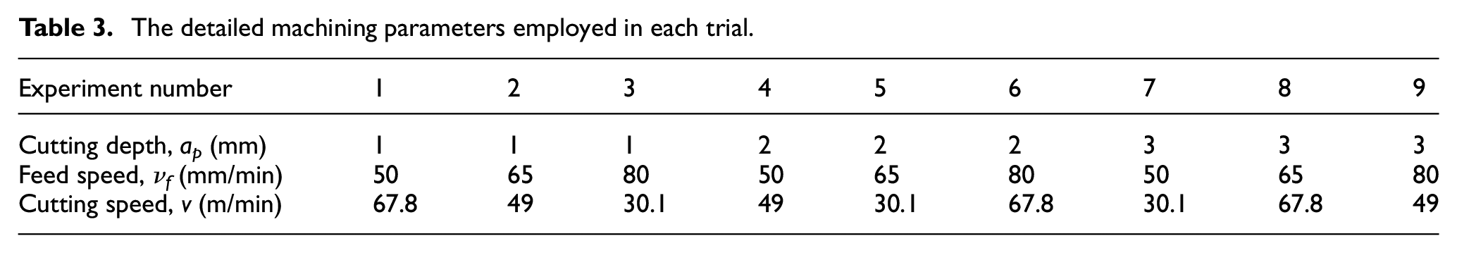
The experimental setup is shown in Figure 1(f) and (g), where the CNC vertical milling machine (Baoji Machine Tool Group Co., Ltd, MVC1000) was used to perform all the trials. The workpiece was fixed on the jig, which was then fixed on the dynamometer (9257B, Kistler) so that the cutting forces can be recorded. The cutter was fed along the workpiece width direction and did the single-pass slot milling operation. The three levels of the milling parameters, including cut depth, feed speed, and spindle speed, were used in the experiments, as seen in Table 2. The detailed parameters employed in each trial were given in Table 3.
The employed milling parameters in the experiments.

The detailed machining parameters employed in each trial.
Measurements
During the experiment, the milling forces were measured by the dynamometer with the sampling frequency of 10 kHz. The captured milling force along the x-axis can be seen in Figure 1(c). Because the force would fluctuate periodically, only the average force calculated by the moving average algorithm was employed in the following discussion (see red line in Figure 1(c)).
After the experiment, the morphologies of both the machined surfaces and the cross-sections were observed by using the optical microscope. The topography of the machined surfaces was measured by the stylus-based surface profilometer. Except for the workpiece, the cutting edges of the two tools before and after the experiments were separately measured by the hardness tester and observed by the optical microscope as well to understand the effect of the DCT.
Results and discussion
Microhardness before the milling operation
Eight points were randomly selected for hardness measurement, and the results were obtained by normal distribution statistics. Figure 2 shows the comparison of the microhardness before the milling operation between the conventional and the DCT tools.

Comparison of the microhardness before the milling operation between the conventional and the DCT tools (Max., Min., and avg. separately refer to maximum, minimum, and average).
It can be found that the DCT increased the tool microhardness. Based on the measurements at eight randomly selected points on the tool surface, the maximum, minimum, and average microhardness was increased separately: 1886 HV (see point 4 in Figure 2), 1717 HV (see point 1 in Figure 2), and 1795 HV for the DCT tool, while 1756 HV (see point 13 in Figure 2), 1615 HV (see point 16 in Figure 2), and 1704 HV for the conventional tool. This means that the DCT increased the maximum, minimum, and average tool hardness separately by 7.4%, 6.3%, and 5.2%.
The hardness improvement induced by the DCT was probably because, on one hand, the low temperature facilitated the phase transformation from the retained austenite to the martensite. During this transformation, the ferrite lattice reconstructed from the face-centered cubic crystal to the body-centered cubic one, increasing the overall hardness of the material due to the carbon supersaturated solid solution in the α-Fe according to Hall–Petch equation as equation (1), that is, the generated ultra-fine carbide increased the material hardness

where
On the other hand, the η particles, referring to multiple carbides of tungsten and at least one metal of the binder, were precipitated at the low temperature, making the matrix materials denser, tougher, and more coherent; strengthening the dislocation; and hindering the intergrain slipping. 18 Moreover, the low temperature lowered the kinetic energy of the atoms, highly reducing the intermolecular repulsion and making the structure lattice more compact.
Cutting forces during the milling operation
Figure 3 shows the comparison of the cutting forces along the x- and y-axis (see the axis definition in Figure 1(g)) during the milling operation between the conventional and the DCT tools. It can observe that, in the mild milling condition, the x-, y-, and z-axis cutting forces were nearly the same for both the conventional and the DCT tools (see the improvement rates of 1.5%, 3%, and 4% in Experiment Nos 1, 3, and 4 in Figure 3(a) and (b)). However, when it came to the aggressive conditions, the forces were reduced by employing the DCT tool in comparison with the conventional tool (the x- and y-directional forces were separately reduced from 1011 and 929 N to 962 and 886 N in Experiment No. 6 and from 1520 and 1041 N to 1460 and 985 N in No. 8 in Figure 3). Moreover, the reduction became even more obvious when the more aggressive machining parameters were employed (see the improvement rates of 4.2% and 12%, and the x- and y-directional forces were separately reduced from 1685 and 1138 N to 1618 and 1015 N in Experiment No. 9 in Figure 3). Experiment Nos 2, 5, and 7 only play a transitional role in the overall trend and law, and there is no inflection point of research significance. Therefore, Experiments Nos 2, 5, and 7 are ignored for the sake of neat and intuitive diagram. Please note that the effect of the DCT on the cutting forces along the z-axis was not obvious; therefore, the comparison of the z-axis forces was not given in this study.

Comparison of the cutting forces along the x- and y-axis (see the axis definition in Figure 1(g)) during the milling operation between the conventional and the DCT tools.
This phenomenon might be explained as follows. The DCT can increase not only the number but also the density of the grain dislocation in the tool materials, and therefore both the strength and the stiffness of the cutting edges were improved by the DCT. Under the mild milling condition, these improvement effects were not obvious because the sharp edges of the conventional tools can also effectively remove materials, and therefore the milling forces were similar between the DCT and the conventional tools. However, when it was under the aggressive milling condition, intensive tool wear would probably happen for the conventional tool and the worn flat area on the cutting edge would result in the more intensive tool–workpiece friction, leading to higher milling temperature and higher possibilities of the adhesive or diffusive wear. Therefore, the sharply increased milling forces can be recognized. For the DCT tool, on the contrary, the sharp cutting edges might be retained for a longer period of time due to the increased strength and the stiffness thanks to the DCT.
It might also notice from Figure 4(e) and (f) that the large-sized edge chipping happened for the conventional tool. Chippings created the crescent moon-like defect and destroyed the original cutting edge geometry, making the edge blunt and inefficient. These chippings decreased the rake angle and therefore increased the shear-induced deformation zone, further increasing the cutting force. At the meanwhile, the rake angle reduction increased the friction at the rake face. Moreover, these chippings decreased the clearance angle, increasing the cutting and friction force at the flank surface as well.
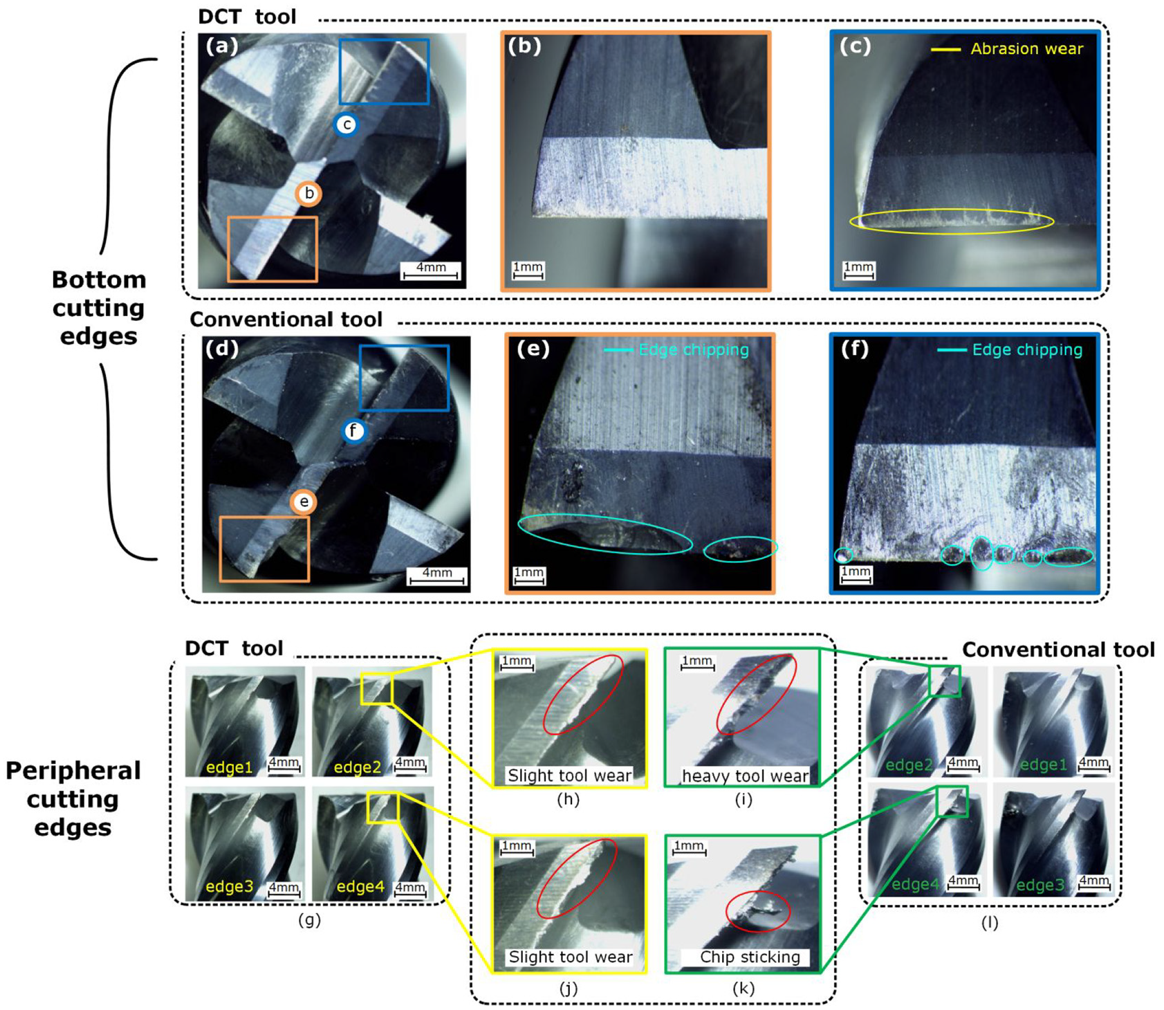
The tool wear and morphology comparison of the bottom and the periphery cutting edges after the milling operation between the conventional and the DCT tools.
Tool wear and morphology after the milling operation
Figure 3(a)–(c) and (d)–(f) separately show the tool wear and morphology comparison of the bottom cutting edges after the milling operation between the conventional and the DCT tools. It can observe that, for the conventional tool, the obvious edge chipping can be found (see Figure 4(d)), where not only the scale-sized material removal with the unclear burn marks discontinuously happened (see Figure 4(f)) but also the large-sized continuous material missing with brittle cracks and fractures (see Figure 4(e)) occurred at the bottom cutting edges. However, for the DCT tools, no edge chipping can be found, and only limited numbers of the abrasion wear morphologies were observed (see Figure 4(c)), showing the better wear resistance, higher stiffness, and strength. 13 This might be because, the DCT might generate not only more fine grains with the increased grain boundary length but also more grain dislocation number and density, leading to the increased hardness, stiffness, and strength. 19
Figure 3(g)–(l) shows the tool wear and morphology comparison of the peripheral cutting edges after the milling operation between the conventional and the DCT tools. It can observe that, although both tools had the obvious wear features, the DCT tool wear can be considered slighter and less in comparison with the conventional tool. The large-scaled needle-like fractured sections in the conventional tools indicated the complete loss of the machining ability of the cutting edges (see Figure 3(i)), and some cutting edge materials were already missing. The DCT tool, however, still showed the relatively complete and sharp cutting edges with very limited numbers of the wear scratches (see Figure 3(h)). The explanation can be similar to the above one.
It might also note that, the chips were sticked at the cutting edges of the conventional tool (see Figure 3(k)) while no similar observation can be found for the DCT tool (see Figure 3(j)). This might be because (1) the element Co was believed as the key factor for the chip sticking because the element Fe in the workpiece and the element Co in the milling cutter were chemically similar elements, and it would be easy to generate the substitutional materials if the two materials contact with each other, and (2) the DCT can effectively avoid the composition segregation of the element Co, enabling the dispersive distribution of the element Co, and therefore the chip sticking was avoided by employing the DCT tool.
On the contrary, the binding phase Co existed in the face-centered form α-Co before the DCT but was transformed into the densely arranged hexahedron ε-Co. These ε-Co crystals enjoyed low friction coefficient, not only lowering the cutting temperature but also increasing the tool wear resistance. The adhesive wear was not unlikely to happen for these ε-Co crystals as well, which can also explain why the DCT tool had the long service life.
Machined surface roughness after the milling operation
Figure 5(a) and (b), separately, shows the comparison of the surface roughness Ra and Rz after the milling operation between the conventional and the DCT tools. This comparison can to a large extent prove the better machined surface quality and probably the integrity by utilizing the DCT tool in comparison with the conventional tool. The surface roughness Ra and Rz by the conventional tool was higher than those of the DCT tool. The maximum, minimum, and average Ra and Rz values of the surface milled by the conventional tool were separately Ra-max of 0.496 µm, Ra-min of 0.31 µm, Ra-average of 0.4 µm, Rz-max of 3.458 µm, Rz-min of 1.988 µm, and Rz-average of 2.61 µm. However, these roughness values were reduced by employing the DCT tool, that is, Ra-max of 0.399 µm, Ra-min of 0.293 µm, Ra-average of 0.34 µm, Rz-max of 2.028 µm, Rz-min of 1.879 µm, and Rz-average of 2.02 µm. This means that the surface roughness machined by the DCT tool was improved by 25% to 70% for the maximum Ra and Rz values, by 5% to 6% for the minimum Ra and Rz values, and 17% to 30% for the average Ra and Rz values.
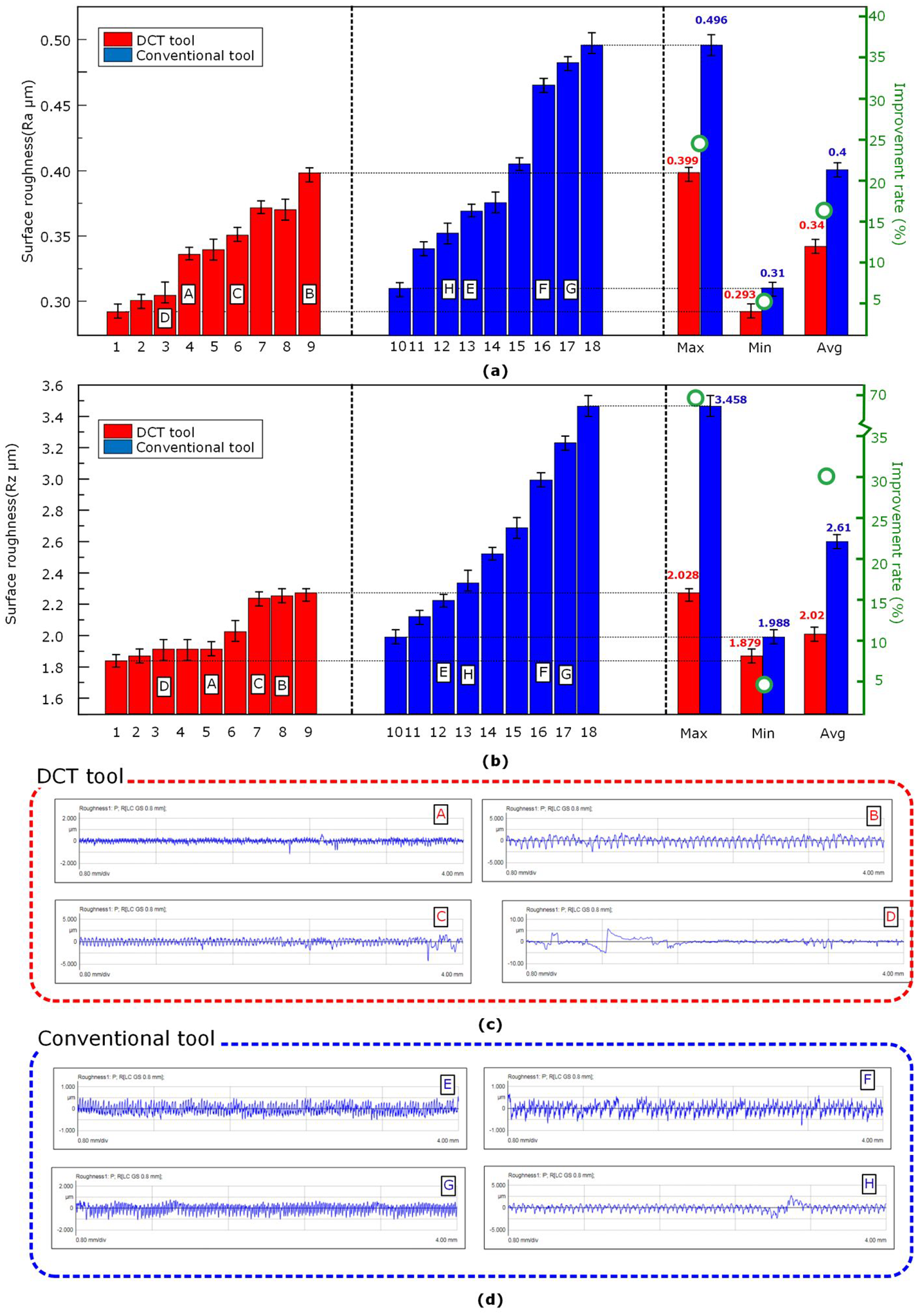
The comparison of the surface roughness Ra and Rz after the milling operation between the conventional and the DCT tools.
The obvious improvement of the machined surface quality can be because (1) the improvement of tool hardness and strength generated during the DCT can properly maintain the tool structure and cutting edge sharpness, and largely reduce the tool edge breakage (chipping), deformation, and wear. Therefore, the tool–workpiece interaction consistency in terms of chip flow, geometry, and shear band behavior can be highly improved; and (2) the milling force was reduced as well (see the “Cutting forces during the milling operation” section), and (3) probably the high milling temperature for the conventional tools easily led to intensive tool wear, generating scratches, burns, and micro cracks on the tool surface, which might further increase the cutting temperature. Therefore, the smoother surfaces can be obtained by the DCT tool. 20
Conclusion
This article experimentally investigated the effects of DCT on WC-Co cutter performances in milling of superalloy GH536. The key findings of this work might include the following:
The DCT increased the tool microhardness by 5.2% to 7.4% in comparison with the conventional tool.
The cutting forces were reduced by around 1.5% to 4% by using the DCT tools, and this reduction can be even more obvious (4.2%–12%) when the aggressive milling condition was employed.
The DCT tool had better wear resistance while obvious edge chipping was found at the cutting edges of the conventional tool;
The machined surface quality in terms of Ra and Rz was improved by 5% to 70% by utilizing the DCT tool in comparison with the conventional tool.
Footnotes
Handling Editor: James Baldwin
Declaration of conflicting interests
The author(s) declared no potential conflicts of interest with respect to the research, authorship, and/or publication of this article.
Funding
The author(s) disclosed receipt of the following financial support for the research, authorship, and/or publication of this article: This work was supported by the North China University of Technology, YuYou Group project and 2018 Green Manufacturing Project, Ministry of Industry and Information Technology.