
Abstract
This article aims to present a minimum-jerk trajectory planning approach to address the smooth trajectory generation problem of 3-prismatic-universal-universal translational parallel kinematic manipulator. First, comprehensive kinematics and dynamics characteristics of this 3-prismatic-universal-universal parallel kinematic manipulator are analyzed by virtue of the accepted link Jacobian matrices and proverbial virtual work principle. To satisfy indispensable continuity and smoothness requirements, the discretized piecewise quintic polynomials are employed to interpolate the sequence of joints’ angular position knots which are transformed from these predefined via-points in Cartesian space. Furthermore, the trajectory planning problem is directly converted into a constrained nonlinear multi-variables optimization problem of which objective function is to minimize the maximum of the joints’ angular jerk throughout the whole trajectory. Finally, two typical application simulations using the reliable sequential quadratic programming algorithm demonstrate that this proposed minimum-jerk trajectory planning approach is of explicit feasibility and appreciable effectiveness.
Keywords
Introduction
The last three decades have witnessed a considerable development of parallel kinematic manipulators (PKMs) which can be treated as positive encouraging candidates for many advanced automation processes and digitalization applications.1–5 Undoubtedly, the apparent advantages of PKMs are low moving inertia, high stiffness, high dexterity, and high payload-to-weight ratio. These distinct characteristics determine PKMs’ increasing widespread utilization in the fields of industrial assembly and practical operations such as high-speed picking and placing, 6 vibration simulator, 7 precise microsurgery, 8 cardiopulmonary resuscitation 9 and so on. When implementing a specific practical engineering task (assembly, spot welding, palletization, or three-dimensional printing), for the sake of decreasing vibration deformation and improving positioning accuracy in the movement, the realistic trajectory should possess remarkable continuity, eminent smoothness, and high operation efficiency. 10
The trajectory planning issue that establishes a parametric function concerning time under several different unambiguous constraints is attracting prodigious research interest between academia and industry.11–13 As a particularly critical part of PKMs design and system scheme, the accurate definition of trajectory can directly affect the choice of drive motors and reduction gears, vibrations, and efforts impacted on the mechanical structure, and tracking accuracy throughout the planned motion. In other words, the actual trajectory determines its real-time kinematics and dynamics performance of PKMs.14,15 If the trajectory has a continuous curvature or even has a continuous higher order derivative of curvature, it is believed to be smooth. 16 The brief framework of common trajectory planning is illustrated in Figure 1, trajectory planner formulates a specific excellent trajectory that must satisfy the indispensable path constraints, kinematics constraints, and dynamic constraints. In the existing scientific and technological literature of robots and manipulators, there are many concrete considerations regarding to traditional trajectory planning topic, the most common of which are minimum execution time,17–19 minimum energy20–22 (or actuator effort), and minimum jerk (i.e. the third-order derivative of position curve with time).23–26 The presence of discontinuity and roughness on the trajectory has been found to correlate with a drastically increase of large jerk value reported in the past several decades.27,28 Limiting the system maximum jerk value, which can diminish vibration influence motivated by the dominant vibration factor of the axis, reduce structure wear and resonance frequency emergence, improve tracking precision, and enhance trajectory smoothness and operational stability, is highly recommended to cope with the trajectory planning problem.29–31 Minimum-jerk trajectory planning theory and methodology relating to traditional serial kinematic manipulators have been intensively discussed and investigated by numerous researchers. Piazzi and Visioli 23 developed a concise approach to globally minimize the maximum of the absolute value of jerk along a trajectory which was easily expressed through cubic splines. The execution time was set a priori, and it was worth noting that the effect of dynamics property was without taking into account. Macfarlane and Croft 24 put forward a jerk-limited and near-time-optimal trajectory planning strategy applied on a general 6-degree-of-freedom (DOF) manipulator, where the accompanying point-to-point trajectory was interpolated using the piecewise fifth-order polynomial function. Gasparetto and colleagues15,26 introduced a minimum time-jerk trajectory planning algorithm of which objective function was to reach a reasonable compromise between the overall task execution time and the total integral value of squared jerk. For the sake of formulation of minimum-jerk trajectory planning for surface-mount assembly robots, Gyorfi and Wu 25 utilized the discretized quintic polynomial curve to obtain an expected trajectory with appealing smoothness and jerk-limited property. To cope with a notable constrained velocity-level path planning issue for traditional mobile robots, Guarino Lo Bianco 32 introduced a seven-segment parabolic velocity curve to fulfill the complicated minimum-jerk trajectory planning assignment of which objective was to minimize the maximum of longitudinal jerk. To bring out a minimum-time trajectory for a two-DOF translational PKM in Cartesian space, Huang et al. 33 optimized the whole travel time as well as imposing the path jerk limitation as an indispensable constraint condition in order to achieve satisfactory smooth performance. For an unordinary high-speed 2-DOF two-dimensional PKM different from Huang et al., 33 Hu et al. 34 proposed an optimal time trajectory planning method using piecewise cubic polynomials in joint space while the inherent dynamic constraints were not taken into full consideration. In general, jerk-level trajectory planning approaches can be frequently employed for addressing the senior complicated trajectory planning problems of traditional manipulators with satisfying stringent continuity requirements and sufficient smooth conditions. Unfortunately, to the best of our knowledge, little research has been devoted to jerk-based trajectory planning techniques applied to three-dimensional PKMs scenarios. It is the increasing demand for formulation of smooth trajectory of PKMs that facilitates the profound theoretical research, imperative practical application, and extensive engineering development of the jerk-based trajectory planning concept.

Brief framework of general trajectory planning.
Generally, cubic polynomials are often used in smooth trajectory generation; 35 however, they provide a constant jerk profile, and they are not applicable to high-level trajectory planning. Higher order polynomials are needed to generate smoother jerk profile. The lowest order polynomials to guarantee the smoothness of jerk profile at the sequence of via-points are quintic polynomials of which jerk profile are quadratic polynomials and with C2 continuity. 23 Also, complete dynamics model analysis without neglecting the inertial and gravitational properties of the struts is essential for trajectory planning. The joints’ actuating torques specific for the given trajectory should not exceed the maximum output torque of driving motors. Due to significant complexity and strong non-linearity in PKMs dynamic equations, the principle of virtual work has high priority over the dynamics analysis approaches of parallel manipulators. Since the generalized trajectory planning problem is typically a complex constrained programming problem with high dimension, non-linearity and non-convexity properties, as well as considering the control system exerts directly on active joints rather than end effector, a dedicated kinematics inversion process is required to equivalently transform the prerequisite path expressed in Cartesian space into a specific corresponding joints’ profile and thereby trajectory planning is usually carried out in joint space. In addition, it is important to note that trajectory planning in joint space can prevent the tricky troubles resulting from kinematic singularities and manipulator redundancy. 14
The practical implication of jerk-based trajectory planning is that since the jerk peak values are limited rationally during the thorough motion period, the optimized smooth trajectory would significantly contribute to reducing structure wear, suppressing dominating vibration, improving tracking accuracy, and potentially extend life cycle. To develop a desirable smooth trajectory for PKMs, this article presents a minimum-jerk trajectory planning approach applied to a 3-prismatic-universal-universal (3-PUU, the underline represents active joint) translational PKM. The remainder of this article is organized as follows. We perform essential kinematics analysis of the 3-PUU PKM in the second section, including position analysis, velocity analysis and acceleration analysis. In the third section, the formulation of complete inverse dynamics model relies on the virtual work principle, where the inertial property and gravitational quality of the struts are not ignored. The forth section describes the detailed process of generating the minimum-jerk trajectory that minimizes the maximum value of the absolute jerk value using piecewise quintic polynomials. Simulation results to demonstrate the effectiveness and feasibility of this proposed minimum-jerk trajectory planning strategy are provided in the fifth section. Finally, concluding remarks are shown in the last section.
Kinematics analysis
As shown in Figure 2, the generalized vertical-distributed 3-PUU PKM is employed a closed-loop geometric characteristic structure which clearly consists of a stationary base, a movable platform, and three kinematic chains with uniform configuration. For every definite kinematic chain, universal joints are utilized to seamlessly connect the slider and strut, followed by association between the strut and moving platform. To generate translational motion of prismatic joint directly, the slider and guideway of a linear leadscrew assembly subsystem are matched and fitted to each other. Note that the three straight guideways are equipped into ideal central axisymmetric layout and perpendicular to stationary base, which allows the overall structure to withstand deformation caused by inertial loads. It is worthy pointing out that the moving platform’s three specific translational DOFs in X, Y, and Z direction necessitate the satisfaction of the definitive geometric conditions, that is, in each PUU kinematic chain, the axis of the first revolute joint of upper U joint needs to be parallel to that of the first revolute joint of lower U joint, and the axis of the second revolute joint of upper U joint needs to be parallel to that of the second revolute joint of lower U joint. Without loss of generality, as indicated in Figure 3, the reference frame

3D model of the vertical-distributed 3-PUU parallel manipulator.

Simplified sketch of the 3-PUU PKM.

Topview of the vertical-arranged 3-PUU PKM.
Inverse position analysis
Give the position of moving platform, a primary closed-loop vector equation is intuitively established to determine the displacement of active joints

where
As depicted in Figure 5, two independent Euler angles

where s and c represent sin and cos, respectively.

Conversion illustration of the local coordinate system.
Equating the third column of

Solving equation (3) for

Taking the Euclidean norm of equation (1) yields
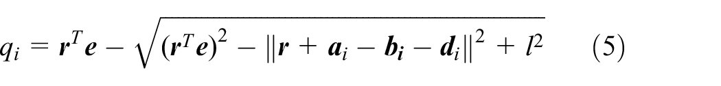
and

Forward position analysis
As a necessary and crucial step in trajectory planning procedure for parallel manipulator, the forward position analysis involves determining the position vector

where

Taking Euclidean norm on both sides of equation (7) gives


Subtracting equation (9) from equation (10), we obtain
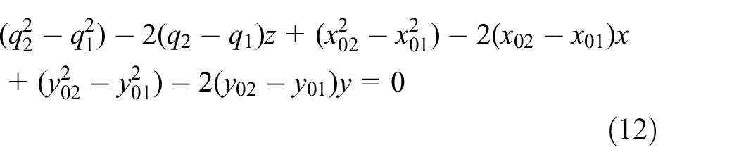
Subtracting equation (11) from equation (10), we obtain

Substituting equation (8) into equation (12) leads to
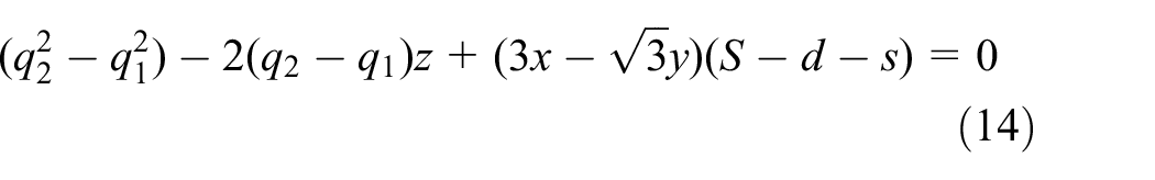
Substituting equation (8) into equation (13) leads to

Combining equation (14) with equation (15), and solving the primary three-variable algebraic equations, we can easily obtain


By incorporating equations (16) and (17) into equation (10), we acquire a general quadratic equation with respect to the variable z, namely

where

According to the structural characteristics and practical situation of this 3-PUU physical architecture, the position of moving platform in z direction can be deduced as

Substituting equation (20) into equations (16) and (17), the value of x and y are derived directly. One potential advantage is that thanks to its pronounced configuration and distinctive geometric layout, there will always exist a unique solution in the forward position analysis with respect to this vertical-distributed 3-PUU PKM, which indicates that the dimensional structure of this 3-PUU mechanical PKM can be invariably confirmed and determined under the precondition of the known input joint value.
Inverse velocity analysis
Taking the derivative of equation (1) with respect to time, the velocity equations of moving platform are described as

where
Utilizing dot multiplication on both sides of equation (21) with vector

Then, equation (22) needs to be rearranged briefly and written in a succinct matrix form

where
Link linear velocity and angular velocity analysis
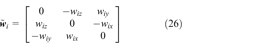
It is important to point out that strut i cannot spin around its own longitudinal aixs; thus,

where
The velocity of the center of the ith strut expressed in the reference frame

Substituting equation (25) into equation (27), then taking a rational simplification yields

The linear velocity and angular velocity of strut i can be further rearranged into a general matrix form, that is

where
Inverse acceleration analysis
Similarly, taking the necessary derivative of equation (21) with respect to time, we can achieve

where
The next step is to perform dot multiplication on both sides of equation (30) by
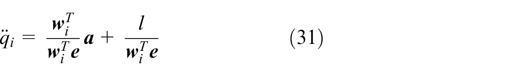
Furthermore, equation (31) can be represented as


where
Link linear acceleration and angular acceleration analysis
Performing cross-multiplication on both sides of equation (30) with the vector

Taking the time derivative of equation (27), it leads to

Substituting equations (31) and (34) into equation (35), and taking a justified simplification lead to the linear acceleration of strut i, that is
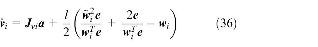
Eventually, complete inverse kinematics modeling is carried out where the link linear acceleration and link angular acceleration play an indispensable role in establishing, analyzing, and estimating the thorough dynamics model.
Dynamics modeling
Except the exhaustive kinematics equations analyzed above, the investigation of dynamics features is essential to the smooth trajectory planning of 3-PUU PKM. 37 First and foremost, we propose two prevalent hypotheses: (1) even though tiny elastic deformations of lightweight struts are inevitable in practice process, all components existing in the whole mechanical system are deemed ideal rigid bodies, which means that they can withstand the applied forces and do not deform; (2) the effect of frictional force among the joints and active components is negligible, and there is no energy loss caused by friction, consequently, the exclusive variation of virtual work is affected directly by the movement of the input and output forces/torques. Based on the system complexity and calculation efficiency, we apply the acquainted virtual work principle to conduct the subsequent dynamics analysis.
Dynamics analysis of the substructure system
From systemic energy perspective, the entire system can be reasonably split into four substructure aspects based on energy coupling principle, including
1. Applied forces of the moving platform. In general, the applied forces and inertia forces imposed at the mass center of moving platform are defined as

The external force
2. Applied forces of the struts. It is clear that the gravitational force is assumed to be the exclusive external force of the rigid struts; hence, the general applied and inertia forces exerted at the mass center of the ith strut in the fixed frame
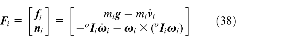
where
3. Applied forces of the sliders. Apparently, the sliders posses single translational movement; thus, the applied and inertia forces imposed on the sliders are

where
4. Applied forces of the motor–coupling–leadscrews. The particular applied forces and inertia forces exerted at motor–coupling–screw are

where
Dynamics modeling of the whole system
According to the virtual work principle, the energy generated by these substructure systems can be seamlessly assembled into a thorough interrelated system, that is

where
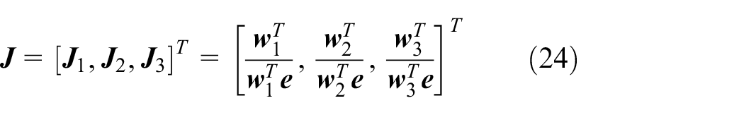
Using the LJM defined in equation (29), the crucial mapping relationship between

Based on the Jacobian matrix defined in equation (23), the corresponding transition relationship between

Substituting equations (40) and (43) into equation (41) and simplifying, the following is obtained

Furthermore, in response to discretional virtual displacement

Substituting equation (40) into equation (45), the actuating torques can be computed as follows
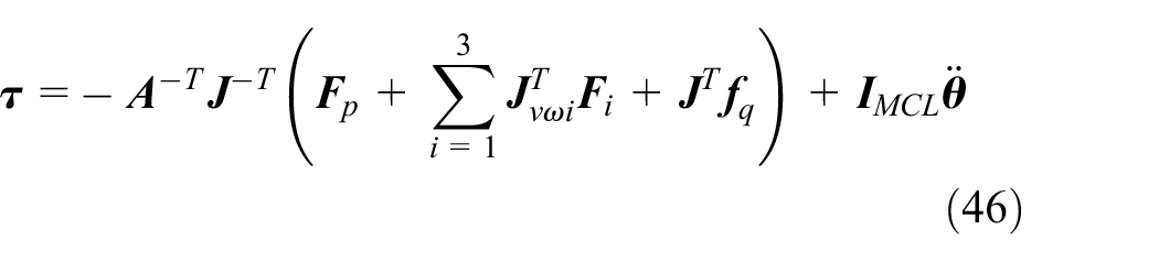
where


Simplifying equation (46), the general formulation of dynamics equations expressed in the joint space can be written as

where
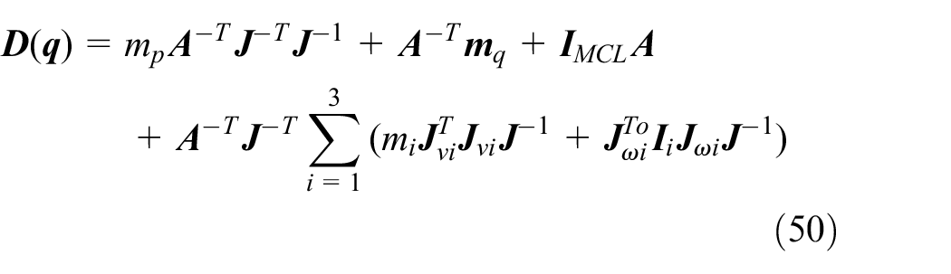


where
Parameterization of trajectory planning based on the minimum-jerk strategy
Rational running trajectory is the foundation of preeminent kinematics property of PKMs, and the quality of trajectory planning algorithm directly affects the dynamics performance of PKMs. As a noticeable drawback, high jerk value during the entire trajectory can decrease the motion precision, excite the dominating vibration, and even break the structure life. Therefore, the minimum-jerk trajectory planning approach aiming to minimize the jerk value of motion period is recommended to regulate the driving joints’ motion functions to make sure all joints pass through the corresponding joints’ positions simultaneously and smoothly.38,39 Considering the actual control system effects directly on the active joints, trajectory planning executed in joint space is more convenient and easier to guarantee the continuity and smoothness of joints’ angular movement curves than that in operation space. Hence, this minimum-jerk trajectory planning approach is implemented by the desired joints’ via-positions which are transformed from the path points in operation space through inverse kinematics calculation.
Interpolation functions based on piecewise quintic polynomials
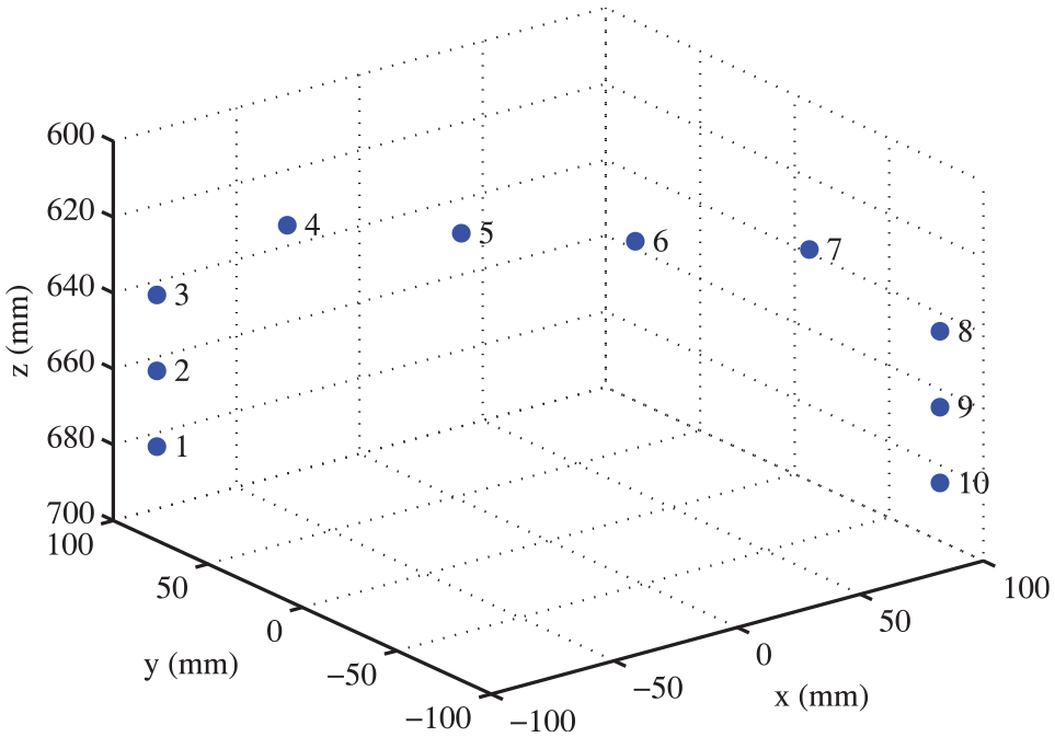
Figure 6 shows a typical geometric description of the sequence of via-points in Cartesian space (i.e. operation space). The fundamental objective and mission of trajectory planning, as stated previously, are to confirm a stringent and reasonable trajectory between the designated starting point and the specific destination within the reachable workspace.
40
In general, the original trajectory in Cartesian space is continuous and discretized into (n – 1) segments by the requisite n via-points. First, the corresponding kth joint angular position knots are defined as

where


Via-points in Cartesian space.
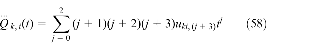
Obviously, the jerk is a quadratic function of time, it has a continuous second derivative (“

Solving equation (59), the coefficients of equation (55) are obtained, namely

Strict and necessary constraints
In particular, the total execution time of our minimum-jerk trajectory planning strategy is set as a specific constraint. Arising from the proposed minimum-jerk trajectory planning algorithm imposed upon the 3-PUU PKM, all strict and necessary constraints consist of (1) meeting the predefined state conditions at the initial and ultimate time; (2) fulfilling the definite continuity and smoothness requirements with regard to position, velocity, acceleration, and jerk for specific relevant via-points; (3) satisfying the explicit kinematics restraints; (4) abiding by the specific dynamics bounds; and (5) subjecting to the limitation of total execution time.
1. Initial and ultimate time constraints. Consistent with the initial and ultimate time prerequisites, the joints’ angular velocity, acceleration, and jerk at initial and final time are undoubtedly guaranteed to be zero simultaneously as follows

2. Continuity constraints. Particularly, the main challenge facing trajectory planner is to achieve the essential continuity and smoothness requirements; therefore, the joints’ angular position, velocity, acceleration, and jerk at every inter-knot must satisfy the following continuity constraints, namely

3. Kinematics constraints. Apparently, kinematics constraints concern that the joints’ angular velocity, acceleration, and jerk at every inter-knot should not exceed the given specific maximum values

where
4. Dynamics constraints. The torque constraint of actuating joint based on its motor’s driving capacity has to be taken into account when the appointed trajectory is reasonably processed, that is

where
5. Total execution time constraint. Generally, as an additional requirement, the total traveling time allocated to the confirmed operation should be less than the given execution time in order to boost the operation efficiency and productivity, thereby
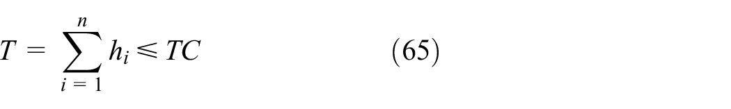
where TC is the artificial traveling time bound.
Objective function
For sophisticated industrial operations, the smoother trajectories are always preferred to the rougher ones; smoother trajectories usually ensure smaller vibration deformation and higher positioning accuracy. Since limiting the maximum jerk value of the entire trajectory is of considerable benefits—reducing structure wear, suppressing motivated vibration, enhancing smoothness degree, and raising tracking accuracy—the maximum absolute value of each individual joint’s angular jerk function within every specific segment needs to be minimized. Hence, the objective function we adopt is given as follows

where n is the number of total via-points (including the starting point and the destination) and m is the number of driving joints. The indispensable coefficients
Optimization method
Figure 7 illustrates an overview of the thorough minimum-jerk trajectory planning procedure aiming at the 3-PUU PKM. From the perspective of mathematics, the complex trajectory planning matter of PKM is further converted into a traditional constrained nonlinear multivariable optimization problem. The objective of this particular optimization problem is to minimize the maximum absolute value of joints’ angular jerk subject to the aforementioned continuity constraints, kinematics constraints, dynamics constraints, and execution time constraints. To solve the optimal solution of the constrained multivariable objective function, the minimum-jerk trajectory generation strategy presented herein has to resort to the professional computing software—MATLAB, which is integrated many distinguished and reliable calculation algorithms including sequential quadratic programming (SQP) algorithm, genetic algorithm (GA), and particle swarm optimization (PSO) algorithm. Among highly efficient methods to deal with general constrained optimization problems, the SQP approach is filled with significant advantages of solving large-scale complex problems and capable of relatively fast convergence rate; thus, we employ familiar SQP algorithm embedded in the fmincon function to fully address the minimum-jerk trajectory planning problem.
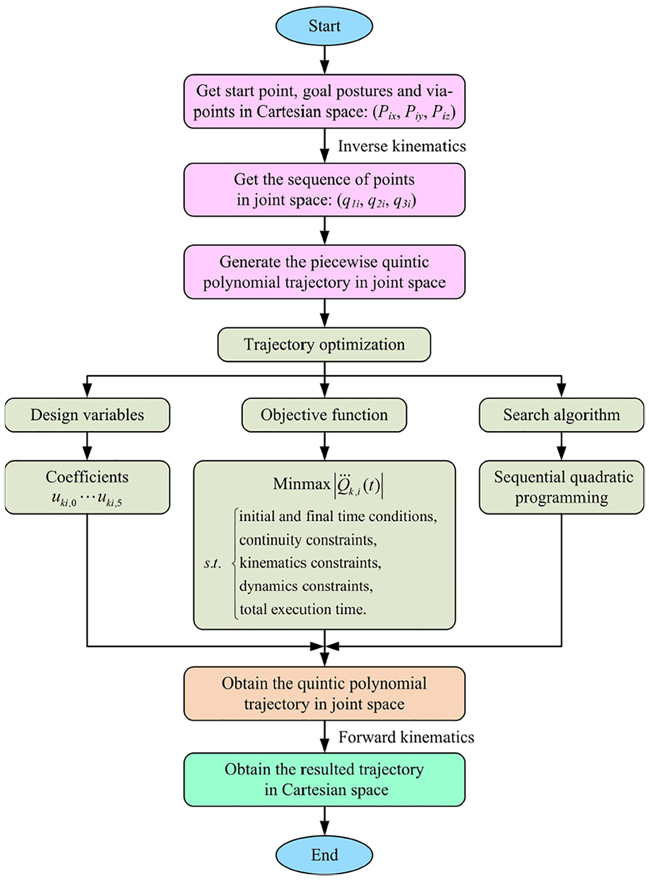
Flowchart of the proposed trajectory planning.
Numerical simulation
The 3-PUU parallel kinematic manipulator is an automatic operation mechanism that can grasp and transport objects or operation tools accurately and flexibly according to the fixed procedures. To intuitively observe and evaluate the concrete characteristics of the presented minimum-jerk trajectory planning approach, two different but representative examples—an inverted U-shaped trajectory intensively applied for pick-and-place operations and a closed spatial circle trajectory widely used for painting or spraying operations—are simulated and discussed in this section.
Case I: pick-and-place operation application
By investigating the handling process of practical production line, the most frequently used trajectory of pick-and-place operation is a bow-shaped trajectory,
41
which is approximately considered as an inverted U-shaped trajectory. As depicted in Figure 8, the red solid line in the dexterous workspace (

The presupposed pick-and-place operation trajectory.
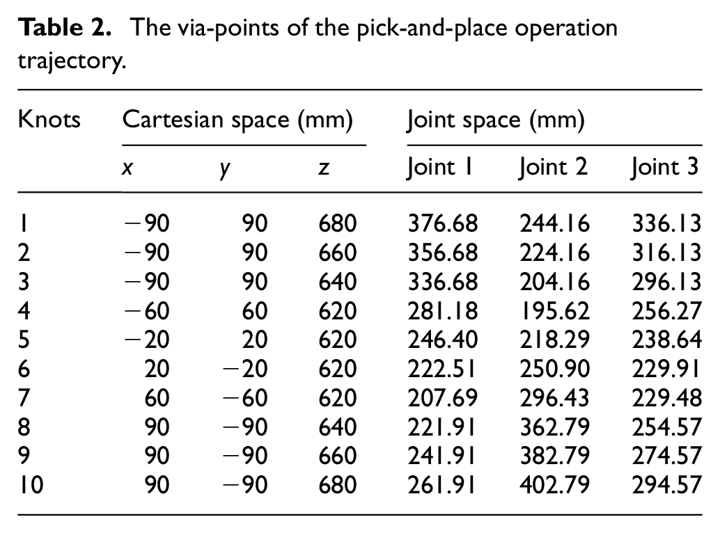
The via-points of pick-and-place operation trajectory.
Physical parameters of the 3-PUU PKM.

PUU: prismatic-universal-universal; PKM: parallel kinematic manipulator.
The via-points of the pick-and-place operation trajectory.
Kinematics and dynamics constraints of the 3-PUU PKM.
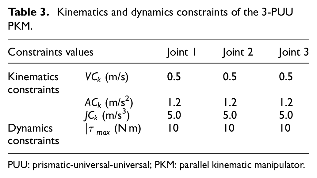
PUU: prismatic-universal-universal; PKM: parallel kinematic manipulator.
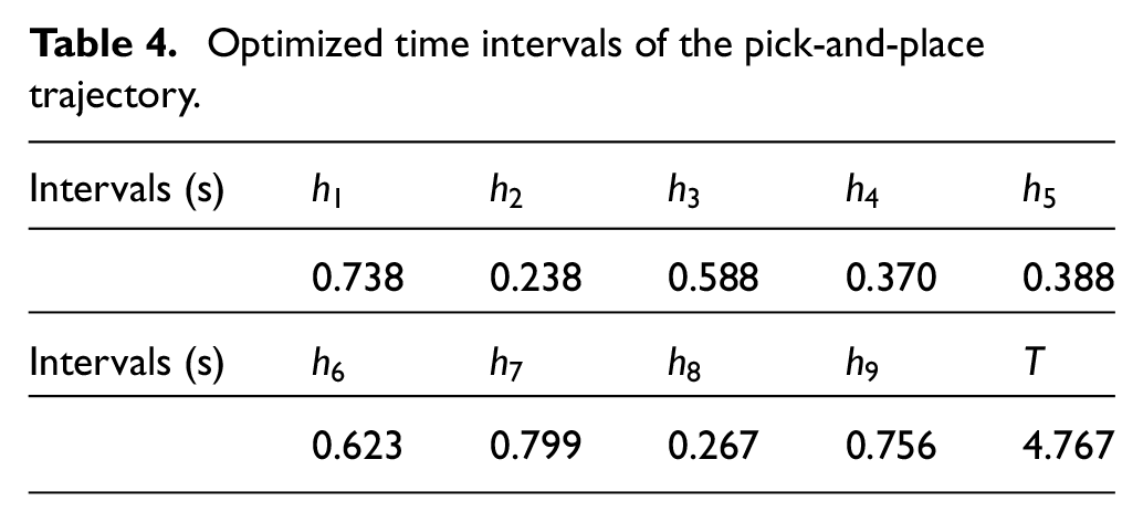
Conforming to the specifically designed procedure for minimum-jerk trajectory planning, the total traveling time after massive computation in MATLAB environment is 4.767 s, as can be seen from Table 4. The four longest time intervals are
Optimized time intervals of the pick-and-place trajectory.
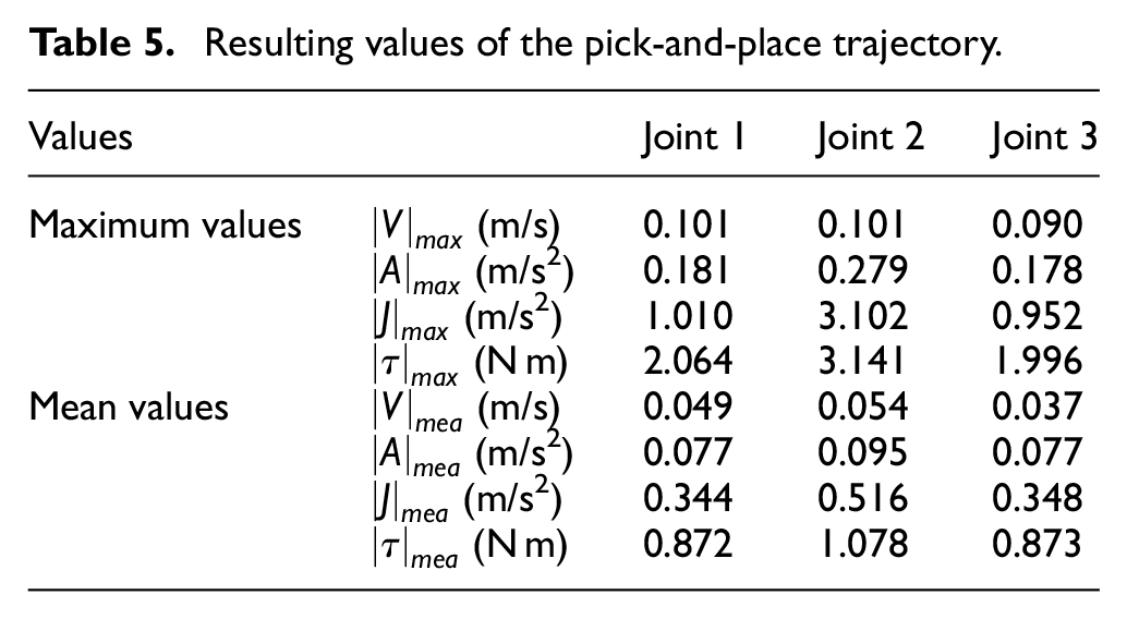
Resulting values of the pick-and-place trajectory.
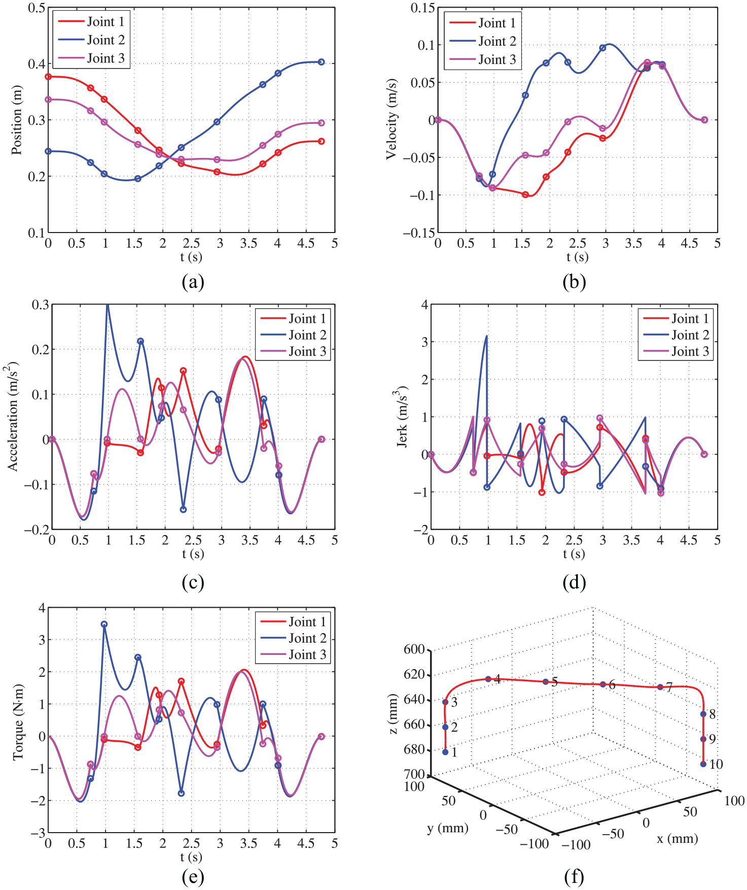
The resulted profiles related to the pick-and-place operation trajectory: (a) joint position, (b) joint velocity, (c) joint acceleration, (d) joint jerk, (e) joint torque, and (f) resulted trajectory.
Case II: closed circle application
This section mainly describes the simulation results of the presented minimum-jerk trajectory planning strategy for a particularly circle trajectory in Cartesian space. The presupposed closed circle trajectory for painting operation is a red dash-dotted line displayed in Figure 11. We choose 11 definite points,
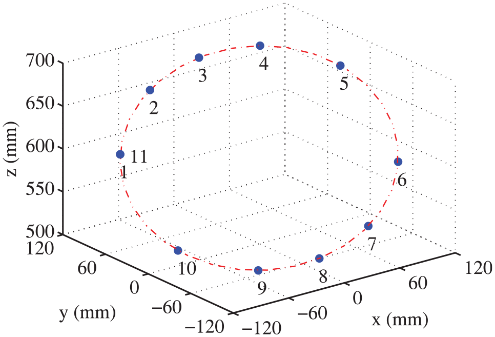
The presupposed circle trajectory in Cartesian space.
Trajectory via-points of the circle trajectory.

The process implementation of Case II, circle trajectory planning, is closely followed with Case I where the major parameter options of fmincon function remain constant to resolve the constrained optimization problem. As can be seen from Table 7, the optimized total traveling time just equals to the setting time bound under the satisfied continuity and smoothness requirements. The four longest time intervals are
Optimized time intervals of the circle trajectory.

Resulting values of the circle trajectory.

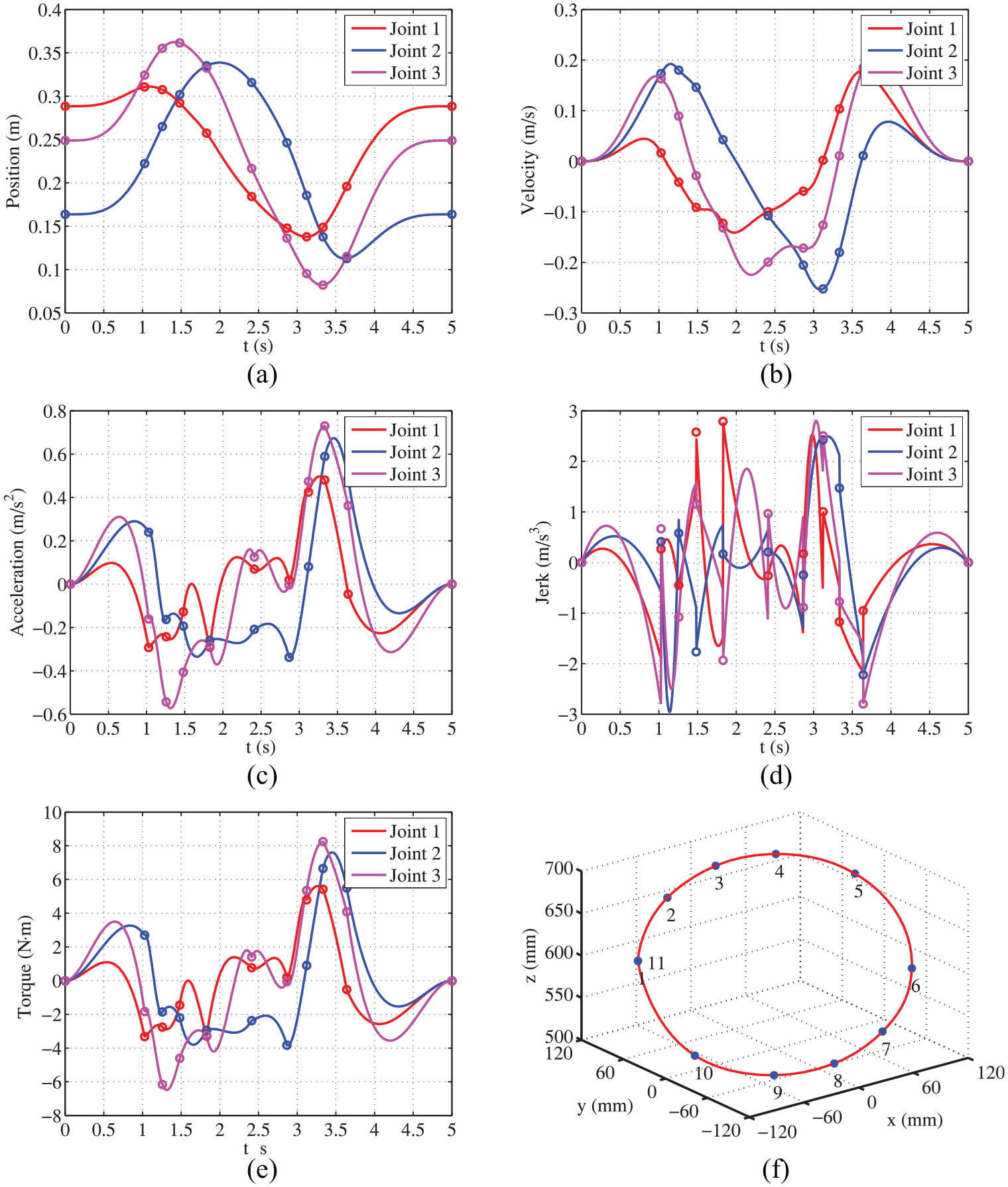
The resulted profiles related to the circle trajectory: (a) joint position, (b) joint velocity, (c) joint acceleration, (d) joint jerk, (e) joint torque, and (f) resulted trajectory.
Conclusion
Limiting the maximum jerk of manipulator’s trajectory contributes to suppressing the vibration induced by the dominating vibratory mode, reducing the structure wear, and improving trajectory smoothness and tracking accuracy. This article focuses on taking jerk minimization as the most important consideration for trajectory planning issue of parallel manipulators. In the presence of specific kinematics constraints, dynamics constraints, and execution time constraints, this article presents a minimum-jerk trajectory planning approach for smooth trajectory generation applied to the translational 3-PUU PKM. Despite a little computational cost, the relatively comprehensive smoothness performance of the proposed minimum-jerk trajectory planning strategy is clearly described and borne out by two hypothesized representative examples. The following conclusions are drawn:
The complete kinematics characteristics of this vertical 3-PUU PKM are thoroughly analyzed. In particular, there exists a reliable unique solution in the forward position analysis aspect of the remarkable 3-PUU parallel mechanism structure. Relying on the LJMs and virtual work principle, the complicated dynamics model is formulated without neglecting the inertial and gravitational effects of the struts.
The straightforward objective of the proposed minimum-jerk trajectory planning is minimizing the maximum absolute value of joints’ angular jerk profile relating to satisfy strict and necessary constraints of initial time, final time, continuity, kinematics, dynamics, and execution time. The discretized piecewise fifth-order polynomials are utilized to interpolate the sequence of joints’ angular position knots which are transformed from a series of predefined via-points by inverse kinematics mapping.
Using SQP algorithm available in MATLAB, empirical simulation results for the inverted U-shaped trajectory and closed circle trajectory demonstrate that the planned trajectory stemming from the minimum-jerk trajectory planning strategy is of significant continuity and pronounced smoothness. In conclusion, this efficient and feasible methodology has substantial contribution for high-level smoothness requirements particularly applicable to the general parallel manipulators.
Footnotes
Acknowledgements
The authors would like to acknowledge the anonymous reviewers for their insightful comments and suggestions.
Handling Editor: Jose Herreros
Declaration of conflicting interests
The author(s) declared no potential conflicts of interest with respect to the research, authorship, and/or publication of this article.
Funding
The author(s) disclosed receipt of the following financial support for the research, authorship, and/or publication of this article: This work was supported by the National Natural Science Foundation of China (grant nos 51575544, 51275353), HuXiang High-Level Talent Project of Hunan Province (grant no. 2019RS1066), Education Department of Hunan Province (grant no. 19C1520), and the Macao Science and Technology Development Fund (grant no. 110/2013/A3).