
Abstract
A pump-as-turbine is a hydraulic machine that can operate as a pump and turbine at the same time. Pump-as-turbine happens to be the most appropriate method for meeting the world’s energy demands, particularly in rural and isolated areas of a country. Furthermore, the operating cost of microhydropower systems is lower compared to conventional hydrodynamic turbines, but it requires high initial investment. Pump-as-turbine has been applied in many engineering fields such as irrigation, sewage, reverse osmosis, water distribution systems, farms, small pump storage power house, and pressure dropping valves. However, pump-as-turbine operates inefficiently at part-load due to lack of flow control device. In addition, the pump generates high flow instabilities in pump-as-turbine mode due to the shift of the best efficiency point toward higher head and discharge. This study extensively discusses the flow mechanism, modifications, and flow instabilities in the pump-as-turbine mode operation. First, the mechanism of the pump-as-turbine can be described as drawing out mechanical energy from the flow in the reverse mode. Since the energy drawn mainly depends on the major hydraulic components of the pump (impeller and volute), many studies have been conducted on the impeller and volute. It can be concluded that high amount of hydraulic losses is generated in pump-as-turbine mode operation. This can partly be attributed to the fixed geometrical parameters such as the stationary volute. To increase the usage of pump-as-turbine, it is very crucial to predict their performance in advance before manufacturing, which requires the understanding of the flow behavior as a result of geometrical parameters. In order to improve the energy conversion and understand the flow behavior in the centrifugal pump functioning as pump-as-turbine, the key geometrical parameters should be carefully designed. The designs of the main geometrical parameters do affect not only the hydraulic performance of pump-as-turbine but also the operational instability. The operational instability of hydraulic machines mainly depends on the pressure and the velocity fluctuation intensity generated within the flow passage as a result of the impeller–volute interaction. The magnitudes of the instabilities have the tendency to cause noise, vibration, harshness, and cavitation which reduces the life span of the hydraulic machine. Moreover, appropriate selection of the pump and unavailability of pump data contribute to the challenges faced. Finally, this review proposes specific solutions in terms of geometrical modifications and improvement of the computational design methods to handle the hydraulic losses faced during the pump operation; thus, this study can serve as a point of reference for a pump-as-turbine performance optimization.
Keywords
Introduction
Lately, electricity has become part of basic mankind needs, but due to the high rising price and environmental hazards of the known energy sources such as large hydropower, oil, and coal production. This situation has limited the access of electricity to some regions of the world, especially in Africa and Asia. The International Monetary Fund (IMF) 1 with its primary commodity price projections stated that after the minimal growth in 2018, the nominal price of Brent crude will increase to US$53.5/barrel by 2020. The World Bank has also anticipated that all three major benchmark oil prices, Brent, WTI, and Dubai, will continue to constantly increase after 2020 to reach US$70 per barrel in 2035 as shown in Figure 1. 2 Again, the literature3–6 drew the attention of the world to the current state of depletion of the ozone layer and the unfriendliness of the oil and gas industry to aquatic organisms. This has shifted the attention of present-day scientists and engineers to find out cheaper and more environmentally friendly methods of generating electricity to mankind. The generation of electrical energy through small hydropower systems remains the best option in tapping energy from water bodies for rural and isolated communities. The cost involvement in setting up a hydropower system is high because of the hydraulic device used.

World energy consumption till 2035. 2
In order to reduce the device cost and to meet the electrical energy requirements globally, researchers have derived other benefits from hydraulic pumps. A pump-as-turbine (PAT) is a small hydropower machine which has the potential to operate as pump and turbine at the same time. It has several advantages over the conventional hydrodynamic turbines because hydraulic pumps are cheap and easy to produce, install, operate, procure spare parts and has a short delivery time. Also, it can operate under different operating conditions.7,8
PAT was discovered when Thoma and Kittredge 9 accidentally identified that hydraulic pumps can operate in reverse mode as a turbine. Thereafter, many researchers globally found interest in the growth of the technology as pump operating as a turbine. Agostinelli and Shafer 10 tested many pumps in reverse mode over the years and concluded that when a centrifugal pump operates in turbine mode; its mechanical operations are quite smooth. Centrifugal pumps are frequently used as PAT because its mode of working is parallel to that of Francis turbine. With centrifugal pumps, the fluid enters at suction port “A” of the pump at low pressure and forced into the impeller passage in Figure 2(a). The impeller increases the absolute velocity of the flow, thus adding up pressure and kinetic energies to the fluid until it flows out at discharge port “B.” In the case of the PAT, the impeller rotates in the reverse mode relative to the pump-mode operation. The flow enters with a very high pressure at port “B” which now becomes the suction in the turbine mode of operation. The impeller at this point absorbs the pressure and kinetic energies from the fluid and converts into mechanical energy. The flow subsequently leaves the pump at port “A” as indicated in Figure 2(b). PAT is a mechanical system that converts energy from a pressurized fluid flowing through an impeller. This energy conversion in a PAT can be expressed mathematically and outlined as depicted in Figure 3. The total pressure difference across a PAT that is, available head is (ΔH) is calculated by taking into considerations all losses. The head losses are categorized as hydraulic and mechanical losses. The hydraulic losses consist of recirculation, flow separation, disk friction, incidence, shock, mixing, and leakage losses, whereas mechanical losses include shaft seal and bearing losses. Subsequently, the available hydraulic power output and efficiency can be determined.

Flow direction: (a) pump mode and (b) turbine mode. 11

A general outline of PAT design.
Although, the primary function of a PAT is to generate electrical energy for rural and isolated settlements, it has been found useful in different fields. Yedidiah, 11 Taylor, 12 and Engeda and Rautenberg 13 utilized its two-phase flow ability in the production of synthetic ammonia gas, heating, and reverse osmosis schemes. Moreover, it has been used widely in sewage treatment and irrigation systems. To increase the usage of PAT, it is very crucial to predict their performance in advance before manufacturing, which requires the understanding of the flow behavior as result of geometrical parameters. In order to improve the energy conversion and understand the flow behavior in the centrifugal pump functioning as PAT, the key geometrical parameters should be carefully designed. The designs of the main geometrical parameters do affect not only the hydraulic performance of PAT but also the operational instability. The operational instability of hydraulic machines mainly depends on the pressure and velocity fluctuation intensity generated within the flow passage as a result of the impeller–volute interaction. The magnitudes of the instabilities have the tendency to cause the noise, vibration, harshness, and cavitation, which reduces the life span of the hydraulic machine. Therefore, the purpose of this study is to examine the performance difficulties and improvements of PAT in a comprehensive manner to provide a useful knowledge and understanding to guide future research, particularly on the efficiency improvement of PAT.
Contributions
The previous studies have made significant contributions to the understanding of the functions of the PAT geometrical parameters. However, improving PAT performance remains a challenge, since the operation of a PAT is associated with high hydraulic losses. The main contribution of this article is to bring to light the current state-of-the-art works done on a PAT regarding the major components involved in the energy transfer process. Moreover, this article discusses the flow mechanism and challenges faced in the operation of a PAT. Finally, the article proposes some solutions to curtail the hydraulic losses and improve the performance.
Effects of geometric parameter on the performance of a PAT
The fundamental difference between pump and turbine is that hydro turbines operate with control device which improves its performance under various operating conditions during water availability and consumer requirement. Meanwhile, centrifugal pumps operate under constant speed, head, and flow to meet specific application requirements. Even though there is a possibility of using PAT without any modification, there have been numerous methods to improve PAT efficiency. Thus, to improve the performance in both pump and PAT modes, the impeller and volute should be carefully designed to reduce hydraulic losses.
Impeller
The efficient operation of PAT has been found to depend mainly on the geometrical parameters of the impeller. In both direct and reverse operating conditions, the impeller plays a key role in addressing various issues, such as flow instability and flow losses. The impeller is the core part and it converts the mechanical energy into pressure energy in pumping mode, and vice versa in turbine mode. 14 Appiah et al. 15 and Zhang et al. 16 indicated that the impeller directly determines the transport capacity which affects the hydraulic performances of hydraulic machines. The impeller geometry consists of the hub, shroud, and the blades that transfer energy to the fluid as shown in Figure 4. The leading edge (LE) and the trailing edge (TE) represent the inlet and outlet of the impeller. The leading face of the blade of the rotating impeller experiences the highest pressure for a given radius and is called the pressure side (PS). The opposite blade surface with the lower pressure is termed the suction side (SS). The geometrical parameters have been extensively studied through experimental, theoretical, and numerical methods.

Meridional section and plan view of a radial impeller and 3D blade.
Singh and colleagues17,18 experimentally showed various ways to modify the pump geometry to improve the performance of a given pump in turbine mode without redesigning its main hydraulic parts. He rounded the impeller inlet of different specific speed pumps and presented a qualitative understanding of impeller rounding effects with respect to the internal hydraulics. Chappell et al. 19 also conducted an experimental work on a centrifugal pump. He proposed that the reduction of the impeller diameter as a means of fine-tuning the PAT performance, but this is required only in very special situations, such as over-dimensioned PAT already installed. Thome 20 also experimentally confirmed that reducing the impeller diameter results in an increase in hydraulic efficiency of PATs. He further suggested that the impeller diameter can be reduced to a suitable degree to reduce the leakage losses. To affirm this suggestion, Mikus 21 indicated that wider reduction of the impeller diameter causes secondary effects which resulted in a decrease in head. Knapp and Daily 22 experimentally cut the discharge tips of the impeller blades leaving the shrouds extended. After experimental test, this modification caused a decrease in the efficiency, but when the shroud is reduced, the efficiency in both pump and turbine modes remained equal. Pandey 23 introduced fixed guide vanes of 75° in the volute casing of a PAT to minimize the losses in kinetic energy. This profile provided a tangential fluid entry across the impeller blades. Singh and Nestmann 18 introduced an effective model to verify the impact of rounding the sharp edges of the impeller on a radial and mixed flow pump as PAT using the experimental method. With an experimental approach, Suarda et al. 24 modified impeller blade tips for efficiency improvement. Grinding was made on the impeller tips of the inlet ends, which in the form of a bullet-nose shape as shown in Figure 5. The test was done by operating the PAT at flow, head, and power at 0.13 m3/s, 13 m, and 0.4 kW, respectively. They concluded that the bullet-nose shape of the impeller blade helped decrease excessive flow turbulence thus increasing the efficiency.

Trimmed the impeller vane tips. 24
Yang et al. 25 modified the impeller by rounding of leading inlet edges of impeller hub or shroud in turbine mode. Radial flow pump of seven modified blades was used for this study. It was deduced that the efficiency improved at all flow rates. With a similar idea, Sun-Sheng et al. 26 showed the influence on splitter blades on the hydraulic performance of a PAT. With the increase in splitter blades, the head decreases, whereas the efficiency increased at all operating conditions. Jain and Patel 27 performed experimental studies on PAT geometry and operational parameters, such as impeller diameter, blade tip rounding, and impeller rotational speed. Rotational speed ranging from 900 to 1500 r/min was applied in the PAT mode. The impeller blade was trimmed about 10%–20% with impeller diameters of 250, 225, and 200 mm. Highest efficiency was recorded at a 10% trimmed impeller operating at 1100 r/min. Finally, an empirical correlation was developed and gave the efficiency predictions in the range of ±10% compared to experimental data. Patel et al. 28 also performed rounding of impeller edges, trimming impeller exit region, hub, and shroud edges rounding of a PAT. The modified designs were examined at a constant speed of 1100 r/min under different flows. After comparing the trimmed and the untrimmed impellers, the trimmed impeller exhibited higher frequency, where the best efficiency point (BEP) was observed at low flows. Also, rounded edges impeller gave optimal PAT performance. Furthermore, Doshi et al. 29 experimentally analyzed the effects of rounding the blades and the inner shrouds on the hydraulic performance of a PAT. For blades, a rounding radius equal to half blade thickness was applied, whereas a radius of half shroud thickness was considered for the sharp inner edges. The experimental results, performed on nine PATs, pointed out a decrease in internal energy losses at PAT inlet. Experimental tests of the varied rotational speed n = 18 to 54 r/min were performed, for which the loss reduction was achieved for lower rotational speeds. For higher rotational speeds, higher variation in torque was observed. Thus, an overall improvement in efficiency, from 1% to 2.5%, was realized, pointing out the possibility of further improvements, by enlarging the volute entry. However, Singh and Nestmann 18 with a theoretical approach developed an efficient model to study the rounding of the sharp edges at the impeller edge on a combination of radial flow and mixed flow pumps as turbines using experimental parameter. Proper rounding of impeller selection provides optimistic answer to the overall efficiency in all operating condition. Yang et al. 25 derived a latest technique to forecast the BEP of a PAT based on pump’s hydraulic specifications. A process also existed for selecting an appropriate pump to function as a turbine in a micro-hydro-site. In a theoretical investigation, In a theoretical investigation, Derakhshan and Nourbakhsh 30 applied the “area ratio” method to calculate for the BEP, where each and every part of pump was estimated by geometric parameter and through performance curves.
The traditional approaches for performance prediction are the theoretical and experimental methods which has limitations of predicting the flow inside turbo machines which are highly complex due to three-dimensional (3D) flow. Many researchers have shown that numerical approach through computational fluid dynamics (CFD) analysis is a reliable tool to capture the flow behavior of a pump machine operating as a turbine and to estimate the performance curves of the turbo machinery. 31 With CFD, complex fluid flow behaviors inside the PAT can be virtually previewed, which can substantially reduce both the design time and cost. A lot of studies have been carried out aiming at PAT flow characteristics understanding and performance prediction. Using CFD methods, Yang et al. 32 studied the effects of three different blade thicknesses on PAT performance. They confirmed that the larger the blade thickness, the lower the efficiency. This is due to the continuous increase in head drop and shaft power contributing to the growth of hydraulic losses within the impeller. Jain and Patel 27 also attempted to fix problem of PAT inability to control flow rate through numerical and experimental analyses. The adjustable guide vane (AGV) system was installed in PAT systems under both modes. The use of AGV produced high performance at different working conditions through various climatic conditions at remote hydro-sites. Fernandez et al. 33 considered a single-suction centrifugal pump running at n = 1750 r/min, by comparing experimental data with numerical simulations with ANSYS Fluent. Figure 6 presents the head, efficiency, and power performance characteristics curves. At part-load conditions, high deviations of about 20% were observed. The deviation reduced as the flow rate increased. Generally, the head curves of both experimental and numerical simulation methods increased as the flow rates increase because of the existence of tangential velocity component at the impeller exit. However, the experimental and simulated head and power curves depicted a very good correlation. In a PAT, the BEP in turbine mode is normally lower than BEP in pump mode, which is due to the complex flow structure exhibited in the turbine mode and higher flow losses operation.34–36

Performance characteristics of PAT at 1750 r/min. 33
Barrio et al. 37 numerically simulated a horizontal-axis single-stage centrifugal pump, operating in both direct and reverse modes, having impeller diameter D = 200 mm and seven blades with logarithmic profile. The performance curves obtained in reference to rotational speed N = 1750 r/min and comparison with experimental data were in good agreement as depicted in Figure 7 for head prediction, in both pump and turbine modes.

Experimental–numerical comparison for head prediction. 37
Volute
The volute casing is a stationary hydraulic component of the pump that guides flow and collects high-velocity fluid; the volute has a significant improvement to pump and PAT efficiency. The volute surrounds the impeller with its cross-sectional area increases from the tongue region to the throat area. The volute does not take part in the head generation; 38 its purpose is to guide the fluid which has gained mechanical energy from the impeller or diffuser and convert it into pressure energy in pumping mode and vice versa in turbine mode. The volute geometry plays an important role in locating the BEP 38 by virtue of its hydraulic losses and its ability to restrict the flow against a given head without incurring any additional losses. The tongue represents the nearest part of the volute to the impeller as shown in Figure 8. 39 The simplest way to modify a pump after purchase is by redesigning the volute by welding guide vanes, to change the cross-sectional area of the passages and angles of the vanes. 40 Fluid can be fed into the volute or discharge through radially or tangentially depending on the shape of the discharge diffuser, tongue, and throat position is very important in the design of an efficient volute casing.

Meridional section and plan view of volute. 39
The flow within the volute casing produces a complex flow structure as a result its geometrical shape. Therefore, poor design of the volute geometry can lead to uneven pressure distribution within the casing. There have been numerous analytical and experimental investigations carried out to reduce pressure fluctuation intensity induced between impeller and volute interaction. The geometry of the volute tongue and the impeller exit region has been attributed to be the core sources of pressure fluctuation with a pump system. 41 The widening of the radial gaps between the rotor and the volute tongue and modification of the TE of the tongue and blade have been some of the effective ways of reducing the intensity of pressure fluctuation. The modifications of the geometrical parameters of the impeller exit region and that of the tongue may bring about variation in the hydraulic performance of the pump. Dong et al. 42 and Alemi et al. 43 experimentally researched on the effect of the geometrical modification of the volute tongue on the hydraulic performances of centrifugal pumps. They shortened the volute tongue and enlarged radial gap between the impeller and the volute tongue. It was established that an unstable operating range appeared which ultimately led to a shut-off condition. However, defining the respective roles of volute tongue shape change and impeller–volute interaction on characteristic instability is difficult, because the magnitude of pressure pulsation caused by the impeller–volute interaction is also reduced in those processes. Chang et al. 44 pointed out that a volute casing with a cross-sectional area that is 10% larger than that of a standard model is optimal at low flow. However, increasing the area tends to modify the pump head characteristics in terms of the overall flow rates and significantly flattens the head-flow curve. Worster 45 presented an overview of the flow in volutes and discussed in detail the geometric parameters of a pump (gap between the impeller and the volute tongue, volute throat areas, shape of volute cross section, surface roughness, etc.) and their effects on centrifugal pump performance. Baun et al. 46 presented concentric volutes, which are characterized by larger gaps between the impeller and the volute tongue and a weaker intensity of the impeller–volute interaction in comparison with spiral volutes, to ensure a stable head-flow characteristic curve in some situations. Increasing the area of the volute cross section and throat expands the stable operating range of pumps. The volute cross-sectional area in the literature45,47 review that the area should not too large or too small, as both conditions lead to pressure distortion. The volute shape has a negligible effect on the performance of turbo machines.48,49 However, the position, shape, and angle of tongue play very important role in avoiding shock and separation losses inside the volute casing as well as noise levels.50,51 Volute with exceeding width than impeller is more efficient as compared to volute having equal width. 52 The radial location of the cross section has a strong influence on the performance of the volute. Proper shaped volute minimizes pressure irregularities around the periphery of the impeller, resulting in equal pressure around volute and hence no radial thrust are exerted on the shaft.53,54 Volute with tangential inlet gives a favorable performance when compared to symmetric volute. 55 Yang et al. 56 suggested a design method to optimize the volute geometry of PAT to enhance its performance. Giosio et al. 57 experimented on volute of a commercial PAT with the aim of modifying the inlet flow control. The experimental results showed that the modified PAT has a wider range of high-efficiency operation than the unmodified pump. Another centrifugal process pump was experimentally studied by Iversen et al. 58 They instrumented the volute with static pressure taps and probes and measured the force on the impeller. They integrated the pressures to obtain static forces, but did not account for momentum non-uniformities. As a result, these forces did not agree with directly measured forces. They also performed a one-dimensional analysis to predict the circumferential pressure variation and a good qualitative agreement was obtained. Flack and Lanes 59 and Kostrzewsky 60 developed a clear laboratory pump–laser velocimetry method to study the flows in centrifugal pumps. The hydraulic pump performance was studied for different tongue clearances and positions. The velocities were measured at various operating conditions. A typical two-dimensional (2D) diagram in Figure 9 shows flow separation on the inside and outside of the tongue at flow coefficients, respectively. It indicates that the reserve flow inside the tongue can occur above design point. 61

Typical 2D diagram of flow separation around the tongue region. 60
Imaichi et al. 62 used a theoretical approach to develop an integral equation to study the interaction of an impeller and volute case. They used this method to predict the unsteady flow due to a finite number of blades on the flow field in a centrifugal pump. They did this for both potential flow and jet-wake flow and applied their results to predict the fluctuating pressures. Chen and Wei 63 theoretically investigated the design rule of hydraulic reaction turbine volute spiral development areas and proposed a high-efficiency volute spiral development areas design rule.
Deng and Chu 64 investigated volute throat area to the centrifugal pump performance and drew a conclusion that the decrease in volute throat area consequently decreases efficiency range thereby steepening H-Q curve. Dean and Senoo65–67 applied a numerical method to study the jet-wake flows due to an impeller in a circumferentially symmetric laboratory diffuser. They used a hot wire anemometer to study the velocity fluctuations and found that the wake occupied 72% of the jet-wake flow. They do not quantify the amplitude of the velocity fluctuations. Using a numerical method, Carter 68 also used a finite element method to model the flow in the volute region. He imposed a stagnation point on the tongue and solved for a circulation that produced this. The circulation was then used to calculate the flow in other parts of the volute. Carter did not consider the flow at off-design conditions. Moreover, Chu et al. 69 presented a numerical study recently to demonstrate that the unsteady shedding of vortices from the cutwater can be an important source of vibration and noise.
Theoretical investigations on PAT
The performances of pump and PAT are not the same; therefore, performance prediction of PAT is very important because it determines whether a selected pump will be able to function at optimum performance for a specific site. Teuteberg
70
established that if PAT curves can be defined, then PAT can become an economical alternative to traditional turbines. A large number of theories and experiments have been found in the literature for the prediction of PAT performance in which relations between BEP in pump and turbine modes are derived based on either efficiency or specific speed in pump mode. The specific speed is one of the core parameters of turbo machinery that characterizes the type of the impeller or runner, that is, radial, mixed, or axial flow, blade shape, spiral casing, and other design features, and is expressed mathematically as

Theoretical approach based upon the analysis of velocity triangles in direct and reverse operations was developed by Fernandez et al. 73 and Yang et al. 74 They stated that the head in pump and turbine mode resulted to be almost equivalent because, in reverse operations, the fluid inlet angle to the impeller corresponds to the volute angle, whereas the outlet angle from impeller is equal to the impeller inlet angle. From this assumption, they formulated a method to predict the flow rate and the head ratios at BEP as


where a*, b*, and c* are the coefficients depending on the specific speed of the pump Nsp, the pump size, the mechanical tolerance, and manufacturing accuracy.
A similar approach was followed by Tan and Engeda, 75 who proposed a prediction criterion to represent the PAT characteristic curves, correlating the characteristic parameters with the specific diameter, Ds parameter, defined, in dimensional form, as

where D (m) is the impeller diameter, Htb is the head (m), and Qtb is the flow rate (m3 s−1) at BEP, respectively. The author experimentally interpolated linear functions between the specific speed Ns and the specific diameter Ds in direct and reverse operations, according to the following formulations


A linear correlation was also derived between the specific speed in direct mode Nsp and the efficiency ratio in direct and reverse mode at BEP, as follows

As a function of Nst, Dst, and ηt, the head drop Htb, the flow rate Qtb, and the generated power Ptb at BEP in the turbine mode were calculated using equations


where ω is the angular velocity in s−1, g is the gravitational acceleration, and ρ is the fluid density.
Chapallaz et al. 40 proposed a PAT prediction method which is solely based on the geometry and not on the pump-mode performance. The method was established on the pump specific speed and the optimum head coefficient from the pump-mode geometry such as (r2/r1 and b2/r2), where r denote radius, b denotes the blade width, and subscripts 1 and 2 denote the rotor eye and rotor tip, respectively, using a graph produce by them. The pump-mode BEP is then calculated, and their performance-based method is used to obtain the turbine-mode BEP.
Derakhshan and Nourbakhsh 30 developed a mathematical relationship (in equation (11)) to predict the BEP of PAT by applying the “area ratio” technique developed by Anderson, 76 and the BEP of the centrifugal pump was acquired through theoretical study, while the discharge, head, power, and efficiency of PAT at BEP were calculated through pump geometry and hydraulic characteristics. It was established that the values predicted by this method were slightly lesser than the experimental data

Burton and Mulugeta 77 also applied the area ratio theory developed by Anderson, 76 which stated that the ratio (Y) of area between the impeller blades at exit to the throat area of volute is the single most important factor in explaining the characteristics of the pump area ratio where (Y) is defined as

The author applied Anderson’s ideas to turbine-mode operation by analyzing the sensitivity of both shock-free entry and swirl-free outlet points to the following five parameters that represent the geometry of the machine: (B/b2, vr, β2, va, and Y) for the relation between B and α2. They conclude that the shock-free entry point (but not the swirl-free outlet point) is like the BEP in pump-mode and is independent of all factors except Y. This implies that using the shock-free entry point as the design point, by means of two conversion factors which are head and flow connecting pump-mode rotor BEP and turbine-mode rotor shock-free entry point. The head factor is expressed in terms of Y, and the proposed flow factor is expressed as constant. However, it is necessary to make wise estimates when applying this technique, of the different losses involved in both modes, first to translate from the pump-mode machine BEP to the rotor values, and then to translate from the turbine-rotor shock-free entry point to the actual machine operating values.
According to Ventrone and Navarro, 78 the shock-free entry point is the BEP; however, it does not correspond to β × 2T = β2, but to β × 2T = β2 − i, where i is an angle that depends on the blade geometry. However, this deviation is likely not due to a boundary-layer effect as they suggest, but to the swirl loss, that moves the BEP away from the shock-free entry point. If this assumption is true, then the procedure to obtain the shock-free point cannot be generalized. However, based on their theoretical approach developed, they multiply the circumferential tip area of the rotor eye (a1) by an obstruction coefficient. This method uses the pump-mode performance data in two ways: the volute angle α2 is obtained from the velocity triangle at the rotor exit for the pump-mode BEP and the peak efficiencies in both modes are assumed equal ηt = ηp. Unfortunately, they do not explain the procedure used to obtain the obstruction coefficient, the volumetric efficiency and the hydraulic efficiency, necessary to establish the turbine-mode BEP. Gulich 79 predicted the performance by analyzing the hydraulic losses in pumps and turbines mode. He proposed a very detail prediction procedure counting all the losses. However, this procedure requires very detailed geometry and testing data. For an actual project, this method is not practical because the manufacturer will not provide detailed geometry and testing data, although the method was claimed to be very accurate. Shahram Derakhshan and Nourbakhsh 30 also did some hydraulic analysis regarding the geometry and losses. However, he did not present an applicable prediction method based on his analysis. However, Shahram Derakhshan et al. 80 and Yang et al. 25 together presented a prediction method as

Derakhshan et al. 80 also presented a new technique to predict the BEP of PAT with reference to pump hydraulic specifications. By applying the experimental data of several radial flow pumps, two mathematical relations were established to predict the complete characteristic curves of a PAT in reference to their BEP. A process was given for selecting an appropriate pump to function as a turbine in a micro-hydro-site

Burton and Williams 81 formulated an analytical prediction of the turbine-mode performance. The volute performance was established by measuring its throat area and the different losses by measuring the wall clearance and the leakage path (length and width of the eye clearance). These procedures are used to calculate the total losses such as leakage loss and mechanical loss. Finally, both losses are subtracted from the pump-mode input power at the BEP, and the results are compared with the hydraulic output power, in order to establish the hydraulic efficiency η t . However, accurate calculation of the viscous shear and diffusion is difficult, because it depends on an accurate knowledge of the internal flows in the pump, and the shape of the flow channels is then the only performance datum used by them to determine the turbine performance. The turbine-mode losses are estimated from the pump-losses without any assumption, as Ventrone and Navarro 78 implemented that ηp and ηt are always equal: the leakage loss is calculated by taking into account the increase in head, the mechanical power loss is assumed to be proportional to the square of the rotating speed, and the hydraulic losses are considered relatively smaller than those in pump-mode, “because in turbine-mode the volute represents a converging, rather than a diverging passage, in which the diffusion losses are lower.” Burton and Williams recognize that the exact turbine BEP will be determined by a compromise between running with no whirl at outlet and running with little shock at entry to the impeller blade.
Geometrical configuration of PAT was analyzed by Barbarelli et al. 82 to develop an operative procedure for optimal PAT selection. Six geometrical parameters were evaluated, namely, the head Htb and flow rate Qtb at BEP, the maximum power, the head at the shut-off, the impeller diameter D, and the dimensional size of pump. The approach was divided in four stages as depicted in Figure 14 in Appendix 2, which requires input parameters of the specific speed in pump-mode operation Nsp and the impeller diameter D. In the first stage, the impeller width was established as a function of both the impeller eye diameter and the blade inclination with respect to the radial direction. In the second stage, the number of blades and the vane angle were calculated. In the third stage, the impeller width, in the region close to the volute, was assessed. Finally, the last stage allowed to design the volute area. The authors experimentally tested six centrifugal PATs with specific speeds Nsp between 9 and 65. The reliability of the proposed model was experimentally verified, in reference to three configurations: the design mode, applied when the geometry was unknown; the geometry known mode, used when the geometric parameters were known; and the mixed mode, in presence of the partial knowledge about the geometric parameters. The comparison with experimental data pointed out the model reliability to predict the BEP conditions, whereas higher discrepancies were estimated for head and efficiency forecasting, in reference to operative conditions far from the BEP. In greater detail, generally higher efficiencies than the experimental data were estimated. Furthermore, lower errors were observed for the geometry-known-mode configuration, drawing attention to the high importance of an in-depth knowledge about the geometric pump sizing to make the applied models effectively suitable.
Effects of geometric parameters on flow instabilities of a PAT
The interaction between the impeller and volute causes an unsteady and turbulent flow behavior of PATs in both operational modes at all operating conditions. The unsteadiness in the flow is very potent to generate noise and vibration which eventually affects the operational reliability. To reduce the instabilities of the flow, many scholars have showed that the magnitude of the instabilities depends on the key geometrical components. The unsteady pressure distributions on the volute casing wall in a PAT were measured by Yuasa and Hinata. 83 The results showed that the fluctuating unsteady pressures due to the interaction between impeller and volute, especially around the volute had a close relation to flow noise and vibration. Zhang et al. 84 predicted the unstable in a PAT operating in a pump mode. Yang et al. 85 numerically performed a detailed analysis of the unsteady pressure field distributions within the PAT control volume and compared the unsteady pressure difference caused by the increase in blade number. The pressure fluctuations owing to tongue in PAT mode were measured, and the results demonstrated that the effect of tongue on the pressure fluctuations is transmitted both upstream and downstream of the volute tongue as depicted in Figure 10. 85 Deng and Chu 64 investigated volute throat area to the centrifugal pump performance and drew a conclusion that the decrease in volute throat area consequently decreases efficiency range, thereby steepening H-Q curve

Pressure pulsation at the volute tongue at design operating condition. 85
Barrio et al. 37 analyze the head across the impeller and highlighted that the head decreases from the external to the internal parts, as a result of the fluid impact on the blades. The generated head drop resulted to be higher at increasing the flow rate, whereas, for lower flow rates, the head resulted to be almost constant in the whole region near the tongue. Conversely, for higher flow rates, a region at lower head was detected between the impeller and the tongue. The analysis of the velocity field pointed out the determination of a recirculation zone close to the blades edges (Figure 11) which caused the efficiency decrease. For higher flow rates, the re-circulating area moved forward the blade SS, generating the fluid shifting across the blades.
Impeller velocity field in PAT operation. 37
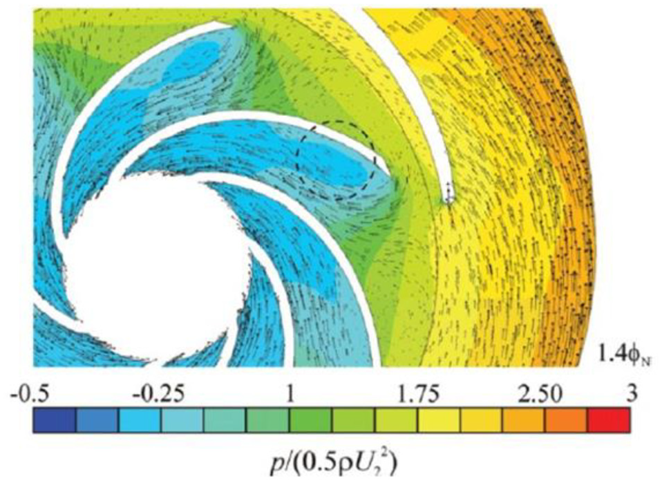
It have been experimentally established that a small change in the volute design parameters has a significant effect on the flow instabilities and the stability of the pump. 46 However, with pump impeller the backward-curved blades are only suitable for pump-mode operation. When a pump works as turbine, the inlet blade angle is fixed within it operating range. A vortex region will be formed due to the inlet angle of attack. The pressure difference between the volute inlet and impeller outlet increases with increasing flow rate, causing the leakage amount to increase. 86 Therefore, the lower efficiency and higher flow instabilities for PAT are usually obtained by the poor design of flow passage and impeller–volute matching. The efficient operations of pump and turbine modes have been found to depend primarily on the geometrical design of the impeller. The impeller plays a vital role in addressing different problems, such as flow instability and cavitation when operating in both pump and turbine modes. Guo and Maruta 87 explained that the pressure fluctuations depend on the flow rates and blade/vane angles. The largest blade pressure fluctuations occur at the TE on the PS, but the magnitudes depend greatly on the number of vanes and vane angle. At off-design operating conditions, pressure fluctuations due to impeller–volute interaction occur mainly at blade passing frequency and its higher harmonics. The circumferential unevenness of fluctuations, which causes sidebands in frequency spectra, is dependent on the flow rate and guide vanes and become more significant at lower flow rates. Parrondo-Gayo et al. 88 conducted a systematic series of experiments to measure the pressure fluctuations on 36 points around the volute of a centrifugal pump for flow rates of 0%–160% of the best efficiency operation. The experimental data indicate that the pressure fluctuations result from the superposition of the hydraulic disturbances and the interaction of blade and volute tongue. Dai et al. 89 found the worst pressure fluctuation in a volute-type centrifugal pump was located at the tongue, and there were some certain relations between the pressure fluctuation and radiated noise on structural surface. Majidi 90 solved the unsteady 3D viscous flows in a centrifugal pump to obtain the unsteady pressure distribution in the impeller and volute. Due to the interaction between impeller and volute, the pressure fluctuations are strong at impeller outlet and at the vicinity of the tongue. Then, Dong et al. 91 studied the flow structure and resulting noise by modifying the tongue geometry based on particle image velocimetry (PIV), pressure, and noise measurements. He pointed out that the contribution to noise from jet/wake phenomenon was insignificant by increasing the gap between tongue and impeller. The major contributor to noise was tongue oscillations relating to its stiffness. Attempts can be made to reduce noise by increasing the gap, adding the tongue’s stiffness, and attaching damping pieces at the tongue. Pavesi et al. 92 carried an experimental investigation of the flow field instability in a centrifugal pump. The results highlighted the existence of an asymmetrical rotating pressure structure at the impeller outlet, and a fluid dynamical origin and propagating both in the radial and circumferential direction appears to be connected with the phenomenon of jet-wake. Li 93 investigated the pressure and velocity fluctuations in two centrifugal pumps with different blade exit angles and liquids by means of experiment and numerical simulation. The results show that a larger fluid viscosity and a smaller blade exit angle can reduce the pressure fluctuation of flow variables. Tamm et al. 94 and Barrio et al. 95 carried out internal flow analysis of a centrifugal pump having seven twisted backward blades in pump and turbine modes using the fluent commercial code. The simulations were carried out by solving the full unsteady Reynolds-averaged Navier–Stokes (RANS) equations with the finite volume method for the flow rates between 20% and 160% after testing the dependence of the numerical predictions on grid and time step size. Turbulent effects were incorporated by means of the renormalization group (RNG) k-ε model together with standard wall functions to calculate the flow variables near solid boundaries. Figure 12 shows a detailed pressure coefficient and velocity vector plots near the tongue region in turbine mode at different flows. The numerical results were compared with the experimental measurements which showed maximum deviations of 3%–5%. In turbine mode, recirculation in the impeller was found at overload flow point, 1.4φN around the highlighted region. The region also displayed weak pressure coefficients of about 0–0.2.

Detailed pressure coefficient and velocity vectors plots near the tongue region in turbine mode at different flows: 95 (a) design flow, ϕN and (b) overload flow, ϕN.
Natanasabapathi and Kshirsagar 96 simulated the flow behavior of a centrifugal PAT. An unstructured mesh was generated by applying the multiple reference frame (MRF) solution with frozen rotor interface to model the relative motion between impeller and volute. The comparison with experimental data showed maximum efficiency deviations when operative conditions displaced far from the BEP were running. Improvements were observed when two rings were geometrically inserted between volute and runner, defining better experimental numerical correlations. Similar results were achieved by Shukla, 97 by analyzing the flow field across the inner flows of a centrifugal PAT, using the ANSYS Fluent MRF approach. Simulated results were compared with experimental data in both direct and reverse operations, observing good correlation in pump mode, whereas greater discrepancies were determined when the turbine mode was running. The model reliability was particularly observed for flow rates close to the BEP, relating to which low physical losses through the volute and the draft tube were shown, whereas the loss increase was observed for the furthest regions.
A different CFD commercial code was used by Derakhshan and Nourbakhsh. 30 They applied the NUMECA FINE™/Turbo software to simulate the centrifugal PAT 3D unsteady flows. The MRF option with standard k-ε turbulence model was considered, setting, as boundary conditions, the mass flow rate and the static pressure for inlet and outlet, respectively. A PAT, with specific speed of 23.5 was modeled and made to operate at different rotational speeds between 750 and 3000 r/min. Comparisons between the numerical and experimental data were made. Errors of ±5% for flow rate, head, power, and efficiency were estimated for pump running in direct operations, and higher errors were observed in reverse mode. The errors of the head and power performances were recorded up to −3% and −16.5%, respectively. However, in turbine mode, simulated head and power produced lower values compared with the experimental measurements. This can be assumed to be the effect of the geometric simplification which neglected the physical interaction between the impeller, the hub, and shroud and the casing. The BEP in PAT was obtained at a rotational speed of 1750 r/min. Gonzalez et al. 98 analyze different operating conditions under CFD codes and revealed a slightly constant velocity field for low and design flow rates, whereas high-velocity fields were observed at the higher flows. However, high efficiencies were calculated in PAT operations, around 80% for operation conditions close to the BEP. Sedlar et al. 99 worked on a multi-stage centrifugal pump with specific speed of 23 working as a PAT. The structured grid was considered for the numerical setup. They set the boundary conditions in ANSYS CFX-Pre as follows. Comparisons between experimental and numerical results showed that the pump-mode operation reached a good agreement, whereas high deviations were realized in the turbine mode.
Su et al. 100 applied the CFX software to simulate a single-stage centrifugal PAT running at 1480 r/min. The turbulence model shear stress transport (SST) k-ω was employed to calculate the 3D N-S equations. The transient-state simulations were performed after the steady-state calculations failed to predict the “true” flow behavior within the PAT. Sun-Sheng et al. 101 studied the influence of impeller trimming on PAT performance through experimental and numerical methods. Note that impeller trimming is generally aimed at pump performance improvement whenever there is pressure head or flow rate drop. Three PAT models—full, once-trimmed, and twice-trimmed impellers—were tested at the same rotational speed of 1500 r/min in both turbine and pump modes with ±0.57%, ±0.50%, ±0.76%, ±1.2%, ±1.27% and ±0.14%, ±0.50%, ±0.52%, ±1.08%, ±1.20%; at respective pressure head, flow rate, hydraulic power, generated shaft power, and efficiency measured uncertainties. The steady- and transient-state calculations were carried out through a CFD codes with the k-ε turbulence model. The experimental results showed the PAT efficiency drop of about 4.11% from full to twice-trimmed impeller diameter. Numerical predictions were in an acceptable agreement with experimental ones, yet comparatively higher, from the neglected losses in numerical analysis. The PAT performance variation was the combined effect of four driving parameters, namely, impeller diameter, blade wrap angle, blade thickness, and inlet blade angle. Again, Sun-Sheng et al. 102 investigated the effect of splitter blades to the influence of PAT’s performance and pressure field characteristics. Steady-state numerical simulations were carried out through a CFD code ANSYS CFX, with k-ε turbulence model; on a single-stage centrifugal pump with and without splitter blades, working at a rotational speed of 1500 r/min. Experimental tests were also performed to validate PAT numerical performance predictions. Results showed an improvement in PAT efficiency with the splitter blades. Ismail and Zen 103 recently with impeller modification determined the internal hydraulic analysis that causes the variations in PAT performance. Unstructured tetrahedral mesh was generated for all the computational domains. The impeller was set to rotate at 1550 r/min to match the four-pole induction generator speed which was used. The modified impeller was done by removing the sharp edges and rounding them to a bullet shape profile. The radius of the rounded profile was selected based on the blade thickness. The simulation results yielded an acceptable level of confidence and accuracy when the manufacturer’s data were compared with the simulation model (Figure 13).
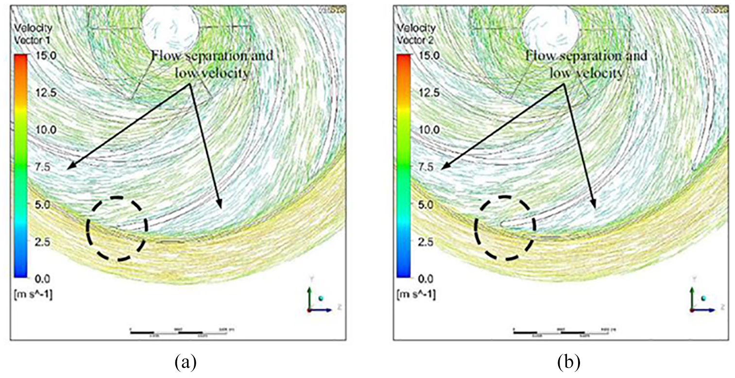
Velocity vector distribution of impeller passage with cut off and rounded leading edges at 17.0 L/s. 103

Flowchart of the geometry modeling.
It can be observed in Figure 12 that there is a wake at the LEs of the impeller inlet for both conditions. The flow layers are detached from the blade surface and separated out from the pressure surface of the blades. The flow layer expanded from the LEs and generated eddies. This can contribute to energy loss in the PAT and influence the flow streamlines along the impeller flow path. The pressure contours for the original impeller and the modified impeller recorded similar pressure drop patterns across the blade passages.
The uncertainties and errors associated with using CFD to predict the flow fields are the integral problems, and there is no standard method for evaluating uncertainty in CFD. One needs to evaluate the uncertainty in the results of a CFD simulation to predict the level of credibility. However, using such simulation tools in a meaningful manner is not straightforward, it has many challenges. Users must develop optimal meshing techniques and select appropriate turbulence models to solve the flow equations in every situation. Moreover, input variables such as boundary conditions, wall functions, fluid properties, turbulence models, solution schemes, and solvers can induce to some level errors into the numerical results. The level of noise and vibration can also cause cavitation in hydraulic machines.
Cavitation in PATs is generated when the pressure drop, caused by the water acceleration across the impeller, is such to determine a downstream pressure lower than the vapor pressure at the operating temperature. It causes the formation of vapor cavities in the moving fluid, implicating both hydraulic and mechanical effects. Gantar 104 from an experimental investigation on a propeller PAT pointed out that the probability of cavitation formation for PATs results to be lower than that in pump operation, allowing to place the impeller at a lower submergence than that required in direct mode. A different approach was undertaken by Gonzalez et al. 98 to investigate the cavitation phenomena of PATs. Indeed, they performed a numerical analysis on a double-end suction centrifugal PAT, observing the formation of cavitation regions at the blade inlet section, at running low flow rate values. Luo et al. 105 modified the pump impeller inlet design through both the extension of blade leading edge (BLE) and blade inlet angle, leading to improved pump operations. Moreover, large incidence angle at extended blade LE were found to considerably improve the pump cavitation performance. In the same respect, through the use of a radial basis function, Singh 106 developed two approaches to evaluate the cavitation formation in PATs: first, based on the machine characteristics, and second, developed by combining the system properties with the geometric configuration of the machine (i.e. runner geometric configuration). A dimensionless combined suction head number (CSHN) was proposed to predict the pressure close to the suction eye region, at varying the rotational speeds N and the geometric settings

where zt is the suction static head, Pr is the pressure, γw is the specific weight, N is the rotational speed, and D is the impeller diameter. Hence, the critical CSHN represented the pressure value, starting from which the cavitation phenomena begun. From an experimental application of the CSHN model to radial flow PATs, the critical value was individuated for higher flow rates than Qtb, whereas flow rates lower than Qtb were established for mixed flow PATs.
Zhang and Zhang, 107 trying to tackle the cavitation problem, extended the impeller blade LE forward along the shroud, resulting in a considerable pump cavitation performance improvement. The tip clearance between the runner blade tip and shroud can lead to tip flow leakage, which in turn results in the emergence of different complex flow structures at the same zones and vicinities, similar work was done by Li and colleagues.108,109 Prasad et al. 110 performed cavitation tests on two end-suction mixed and axial flow PATs, correlating the efficiency with the variation of the cavitation coefficient σt. An increase in PAT efficiency was also observed by reducing σt, up to an operative condition which generated a sudden drop, making the efficiency null. Liu and colleagues111,112 recorded the pump efficiency gradual degradation with an increase in blade tip clearance, where tip leakage vortex eventually got enhanced. The latter was also found to be highly sensitive to the pump flow discharge. The same phenomenon was explored by Y Hao and L Tan, 113 where not only the influence of the tip clearance size was investigated but also its symmetry or asymmetry effect to the pump cavitation performance. The tip clearance asymmetric feature exhibited worse pump cavitation performance where the corresponding radial force fluctuations were seven times the ones with a symmetric design. For pumps pumping viscous fluids, the friction losses on the rotor are much higher than the normal water pump case, which in turn affects their performance.
Conclusion
Although there have been several studies into the flow mechanism of a PAT using different geometrical parameters, the flow principles have not been fully understood. From the above review, the following conclusions have been drawn.
First, when a pump changes fluid flow direction, it can work effectively for power generation without any mechanical failures and present many advantages over conventional turbines, especially in hydropower generation. However, the selection of appropriate pump to be used as turbine has been a challenge to both manufacturers and uses of PAT. The performance of a PAT mainly depends on the impeller and volute geometrical parameters. However, the interacting between these parameters generates a lot of flow instabilities and flow losses. Nonetheless, given that most of these hydraulic losses and flow instabilities occur in the flow zone of the impeller, these flow instabilities and it related damage can be regulated by impeller design changes as illustrated by various researches.
Second, the impeller profile in PAT mode should be modified to reduce hydraulic loss. The backward-curved blades are only suitable for pump-mode operation. In PAT mode, the inlet blade angle is fixed within its operating range and the inlet angle of attack generates a lot of vortex. The pressure difference between the volute inlet and impeller outlet also increases with increasing flow rate, which creates a lot of leakage and lower efficiency. PAT hydraulic losses can be reduced with some modification of the impeller geometry such as impeller diameter, blade tip rounding, blade thickness, hub and shroud edges rounding, and blade wrap angle.
Third, the volute plays an important part in locating BEP, by virtue of its hydraulic losses and its ability to restrict the flow against given head without incurring much additional losses. The volute of hydraulic pump is designed for an optimum flow rate condition. When the pump operates at off-design condition, impeller outflow does not match the volute geometry; as a result a non-uniform angular pressure distribution is established, resulting in flow instabilities. These flow instabilities generate several troubles in hydraulic pump such as noise and vibration. The internal flow characteristics at off-design conditions are extremely complex due to the nature of the blade curvatures, rotor-stator interaction, turbulence effects, and flow separation. There phenomena should be address by optimizing the volute geometry. The energy transfer in PAT system takes place between the interactions of the volute and impeller geometry. Investigating the flow inside the volute helps in determining the passage losses of the volute. As per the geometry of the impeller, flow is discharge into the volute in pumping mode. The behavior of the flow from the impeller to volute is quite complicated and needs detail understanding for a better design.
Finally, due to the lack of experimental data of PAT, the researchers have sought to build a theoretical model that would accurately predict the turbine operation of pumps at BEPs. Most of these studies have proposed relationships to predict PAT characteristic curves either on the basis of efficiency or specific speed of the pump, and some also based their relationships on experimentation or the geometrical parameters of the pump. However, the findings of these studies deviate from the experimental data making it inapplicable. Although there exist high uncertainties among the prediction methods, they can serve as a theoretical reference when designing a PAT. Presently, the approach in which the turbine performance is solely determined based on the pump’s geometry has proven suitable, but it has been established to be unreliable, because pump manufacturers do not follow a universal standard. This means that two pumps with the same BEP may have different turbine-mode performances due to differences in geometrical parameters. Although a great deal of studies have been carried out on the PAT performance prediction, there is still no universal prediction method applicable for a wide range of specific speeds. Therefore, the use of advanced computational models to simulate the performance of pumps in reverse mode can be a solution to overcome the prediction problems.
Footnotes
Appendix 1
Appendix 2
Geometrical configuration of PAT by Derakhshan et al. 80
Handling Editor: James Baldwin
Declaration of conflicting interests
The author(s) declared no potential conflicts of interest with respect to the research, authorship, and/or publication of this article.
Funding
The author(s) disclosed receipt of the following financial support for the research, authorship, and/or publication of this article. This study was financially supported by China Postdoctoral Science Foundation (Grant No. 2018M632244), Natural Science Foundation of Jiangsu Province (Grant No. BK20180879), High-level Talent Research Foundation of Jiangsu University (Grant No. 18JDG012), National Key Research and Development Plan Project (2018YFB0606103), and Construction of Dominant Disciplines in Colleges and Universities and Universities in Jiangsu.