
Abstract
The geometric parameters (ratio of orifice’s length to diameter, conical angle, and inner-wall roughness) of conical nozzle are investigated via computational fluid dynamic method to reveal the effect on the flow and cavitation characteristics. The variation of geometric parameters affects the distribution of the static pressure and the drag force, which in turn affects the mass flow rate at the outlet. The results indicate that the conical angle plays a dominant role in effecting the flow and cavitation characteristics. The higher the intensity of cavitation, the more notable the effect of geometric parameters on cavitation characteristics.
Keywords
Introduction
Conical nozzles widely exist in many cases of hydraulic components, and the variation of the nozzle’s geometry can affect the flow characteristics of hydraulic valve1–3 and the intensity of cavitating jets.4,5 Cavitation occurs when local static pressures reach below the vapor pressure of the fluid medium. The growth and collapse of vapor bubbles can cause flow instability, and even affect the flow structure.6,7 For the water jet propulsion system of autonomous underwater vehicles (AUVs), the conical nozzles can effectively suppress the onset of cavitation compared to the cylindrical nozzles.2,8,9 In order to reveal the effect of geometric parameters on the energy conversion efficiency of water jet propulsion system of AUVs, it is necessary to study the effects of geometric parameters of conical nozzles on the flow and cavitation characteristics.
With the aim to reveal the flow and cavitation characteristics inside nozzles, Nurick 10 pointed out that the minor variation of entrance sharpness has an important effect on the onset of cavitation. Benajes et al. 11 and Liu et al. 1 demonstrated that the conical nozzles are more efficient than the cylindrical nozzles since the conicity suppress the formation of cavitation. Payri et al. 12 concluded that increasing the hydrogrinding radius of the orifice’s inlet can increase the outlet average velocity and flow coefficient. From the above analysis, the conical nozzle can increase the average velocity and the flow coefficient by suppressing the formation of cavitation, so it can be more efficient than the cylindrical nozzle.
The development of computational fluid dynamic (CFD) simulation methods provides more convenience to study the flow and cavitation characteristics. Due to the cost and time-saving advantage compared to the experimental method and the overcoming of actual-model experiment feasibility, 13 the CFD methods have been widely employed. Jian et al. 14 used the software Fluent to study the shock waves at cloud collapse in the Venturi geometry. Schmidt et al. 15 analyzed the effects of inlet angle on the flow characteristics. Som et al. 16 investigated the effect of nozzle orifice’s geometry on spray, combustion, and emission characteristics. There are more researchers who studied the flow and cavitation characteristics using numerical methods, and it can be concluded that the conicity could prevent a notable change in flow direction and flow resistance despite the increment in pressure difference.13,17,18 Due to the advantages and conformance of CFD method, authors also utilized the CFD method to investigate the geometric parameters of conical nozzles in this article.
Inner walls are considered to be smooth in previous studies, yet more and more researchers are taking into account the effect of the wall roughness. Echouchene et al. 19 conducted a simulation on wall roughness effect on cavitating flow inside the sharp-edged inlet nozzle. Sun et al. 13 and Wang et al. 20 found that the inner wall can improve the flow characteristics by suppressing the intensity of cavitation. However, the research on the wall roughness effect on cavitating flow inside conical nozzles is few.
For the numerical simulations on the cavitation characteristics, Yuan and Schnerr 21 proposed a new model to simulate supercavitation and hydraulic flip. Jia et al. 22 conducted a simulation on cavitation using mixture multiphase and full cavitation models. Battistoni et al. 23 compared the prediction capabilities between mixture and multi-fluid models for simulating cavitation inside small nozzles. Since the mixture model predicted the cavitation well,7,24 in this article, the mixture multiphase model is adopted to evaluate the effect of geometric parameters on the flow and cavitation characteristics inside conical nozzles.
Numerical simulation
Considering the symmetry of conical nozzle’s geometry, the nozzle’s axis is treated as symmetrical axis, as shown in Figure 1. No-slip condition has been applied on the wall, the flow fluid is considered to be isothermal and incompressible, and the fluid medium is treated as Newtonian fluid. The operation condition is the relative pressure. The computational domain is discretized using ICEM preprocessor, and the structured mesh is adopted to get a better convergence behavior.

Geometric sketch of the conical nozzle (flow direction is from left to right).
The working fluid is pure tap water with density ρl = 998.2 kg/m3, viscosity μl = 1.003 × 10⁻³ Pa·s; the water vapor with density ρv = 0.02558 kg/m3, μv = 1.26 × 10⁻⁶ Pa·s. The effects of temperature can be neglected on density and viscosity.
The commercial code ANSYS Fluent 14.5 is used to perform the CFD calculations, and the mixture multiphase model is chosen to describe the multiphase flow.13,19 The k−ω shear stress transport (SST) turbulence model is adopted to predict the turbulent flow, and the Zwart–Gerber–Belamri cavitation model is adopted to model the cavitation flow. 8
Multiphase model
The mixture model is employed, which is considered as a “single phase” with its physical properties varying according to the local concentration of liquid and vapor.19,25 The fluid flow is assumed to be pseudo-unsteady. The continuity and momentum equations, which describe the mixture flow in Cartesian coordinates, are presented as follows 26


The mixture properties are approximated as

where
Similarly, the mixture viscosity is expressed as

where

The vapor mass fraction f can be determined by the cavitation model.
Turbulence model
The k−ω SST turbulence model combines the advantages of the standard k−ε and k−ω models,
27
which is validated for good prediction of the boundary layer detachment characteristics.
28
The turbulence kinetic energy k and the special dissipation rate

and

where
The turbulent viscosity

where
Cavitation model
According to the work of Singhal et al., 29 the transport equation of vapor mass fraction can be presented in the following conservative form

where v is the vapor phase;
The mass transfer rate can be derived from a simplified Rayleigh–Plesset model. Zwart et al.
30
proposed to replace
If

If

where the bubble radius
The phase-change threshold

where the saturation vapor pressure
For the drag coefficient of two phases and slip velocity of two phases, the Schiller–Naumann and Manninen et al. methods are selected, respectively.
Equations of Schiller–Naumann’s method
where
Equations of Manninen et al.’s method
where
where d is the diameter of the particles (or droplets or bubbles) of secondary phase p, and
Mesh sensitivity analysis
In order to confirm that the convergence of computational results has been reached, three different cell numbers (17342, 48902, and 96462) are used to compare the convergence of numerical results. The main geometric parameters of the conical nozzle are shown in Table 1. The variations of vapor volume fraction along the axis and the inner wall are selected to indicate the convergence of numerical results, as shown in Figure 2(a) and (b). The inlet relative pressure is set to 40 MPa, and the outlet relative pressure is set 0 MPa to model the working pressure.
Main geometric parameters of the conical nozzle.


Vapor volume fraction under different boundary and inlet conditions: (a) along the axis, pin = 40 MPa and (b) along the inner wall, pin = 40 MPa.
As shown in Figure 2(a) and (b), for the vapor volume fraction, when the cell number is refined from 17342 to 48902, the average relative uncertainties are, respectively, 57.45% and 24.59% along the axis and the inner wall. The numerical results vary notably, which means the convergence has not yet reached. When the cell number is refined from 48902 to 96462, the average relative uncertainties along the axis and the inner wall are 7.84% and 3.18%, respectively. Both the relative uncertainties are less than 8%, so the results indicate an acceptable agreement between two different mesh configurations. The further refinements of the mesh size need more computational time, so considering both the convergence of numerical results and the dissipative time in this article, cell number 48902 is utilized.
Validation of numerical model and setups
Before applying the numerical model for simulating the cavitation flow inside the conical nozzle, Liu et al.’s
1
experimental data are utilized for the validation. The geometric parameters of the nozzle were as follows: inlet diameter d1 = 10 mm, outlet diameter d2 = 2 mm, conicity length l1 = 10 mm, and cylinder length l2 = 10 mm. The volume flow rate of the calculated and measured results versus different square roots of pressure drop (

Comparison of volume flow rate at the outlet between experimental and numerical results under different
Results and discussions
The parameters such as mass flow rate and average velocity at the outlet can be used to describe the cavitation flow inside the conical nozzle


where A is the cross-sectional area,
In this section, the pressure drop
Effect of the ratio of orifice’s length to diameter on the flow and cavitation characteristics
The detailed information on l2/d2 of the conical nozzle is shown in Table 2, and the contour distribution of physical parameters with d2 = 2 mm under different l2/d2 is shown in Figure 4. Prolonging l2 hardly affects the distribution manner of the static pressure and the vapor volume fraction inside nozzles. When the value of l2/d2 is 1 and 2, the flow pattern is in the cavitation flow due to the onset of cavitation. Increasing the value of l2/d2 from 3 to 5, the flow pattern in the cavitation flow is followed by the attachment. For the contours of mass transfer rate as shown in Figure 4, a negative value means the cavitation collapse being dominant at local flow field and a positive value means the cavitation growth being dominant at local flow field. Inside the conical nozzle, the onset of cavitation happens near the corner due to the low static pressure induced by sharp change in flow direction. The increment in l2/d2 has little effect on the intensity of cavitation as seen from the contour distribution of the vapor volume fraction and the mass transfer rate.
Detailed information on l2/d2 of the conical nozzle.


Contour distribution of physical parameters under different l2/d2 (d2 = 2 mm).
As shown in Figure 5(a), the flow coefficient almost remains constant along with the increment in l2/d2. Under different l2/d2, the flow coefficient is 0.8656, 0.8585, and 0.8545 for diameters (d2) 1, 2, and 3 mm, respectively. The drag force acting on the fluid can decrease the flow coefficient. 19 For the conical nozzles, increasing the drag force acting on the fluid by lengthening l2 has little effect on the flow coefficient. So d2 is kept constant, and lengthening l2 has little effect on the flow coefficient, as shown in Figure 5(a).

Variation of different physical parameters under different l2/d2: (a) flow coefficient and (b) vapor mass flow rate at the outlet.
Keeping the inlet and outlet pressure constant, pin = 40 MPa and pout = 0 MPa, the value of flow coefficient of d2 = 1 mm is higher than that of d2 = 2 and 3 mm. Decreasing the d2/d1 from 0.3 to 0.1 will weaken the change in flow direction inside nozzles with the same inlet pressure pin and inlet diameter d1, so the flow coefficient of d2 = 1 mm is higher than that of d2 = 2 and 3 mm. The conicity affects the flow pattern in the nozzle, which affects the flow coefficient. Only within the present range of the conicity, the effect can be small.
As shown in Figure 5(b), the vapor mass flow rate at the outlet decreases linearly along with the increment in l2/d2. Prolonging l2 will increase the drag force of inner wall acting on the flow fluid linearly, which in turn increases the quantity of the cavitation bubble breakage and the cavitation bubbles dissolve back into the fluid flow when the pressure recovers. So, increasing the drag force can decrease the cavitation bubbles at the outlet. With the increment in l2/d2 from 1 to 5, vapor mass flow rate decreases by 78.16%, 49.32%, and 38.66% for d2 = 1, 2, and 3 mm, respectively. The effect of variation of l2/d2 on cavitation bubbles at the outlet will be enhanced under higher intensity of cavitation condition.
Effect of conical angle on the flow and cavitation characteristics
From the analysis in section “Effect of the ratio of orifice’s length to diameter on the flow and cavitation characteristics,” inside the orifice, the cavitation flow followed by attachment will occur when l2/d2 ≥ 3. So l2/d2 = 3 is selected in next parts (sections “Effect of conical angle on the flow and cavitation characteristics” and “Effect of inner-wall roughness on the flow and cavitation characteristics”) to analyze the effect of conical angle and roughness on the flow and cavitation characteristics. The detailed information of the conical angle is listed in Table 3.
Detailed information of the conical angle of the conical nozzle.

The contour distribution of physical parameters under different β is shown in Figure 6. With diameter d2 = 2 mm, the increment in conical angle will increase the gradient of static pressure inside the orifice, which makes the static pressure lower and changes the flow direction more sharply. So along with the increment in conical angle, the intensity of cavitation inside orifice will be enhanced and the value of mass transfer rate will be increased, especially near the corner inside the orifice.

Contour distribution of physical parameters under different β.
From the analysis in Figure 6, enlarging the value of conical angle β will increase the intensity of the cavitation, and the onset or enhancement of cavitation inside the orifice will diminish the effective flow area of the fluid medium. At the same time, increasing the conical angle β makes the vena contracta of the fluid flow more notable, which in turn diminishes the effective flow area. So, the flow coefficient decreases along with the increment in β, as shown in Figure 7(a). The variation of flow coefficient along with β shows linear relation, and the slope is −0.00371. The value of diameter is related to the value of coefficient, but not the slope. The flow coefficient decreases by 29.27% when β increases from 21.8° to 90°.

Variation of different physical parameters under different β: (a) flow coefficient and (b) vapor mass flow rate at the outlet.
As shown in Figure 7(b), as the intensity of cavitation inside the orifice is enhanced along with the increment in conical angle β, the vapor mass flow rate at the outlet increases along with the increment in conical angle β. Increasing β from 21.8° to 90°, the vapor mass flow rate at the outlet increases by 400.51%, 270.13%, and 230.14% for d2 being 1, 2, and 3 mm, respectively. Enlarging outlet diameter d2 will increase cavitation bubbles at the outlet under the same inlet pressure pin and inlet diameter d1. The effect of variation of β on cavitation bubbles at the outlet will be enhanced under higher intensity of cavitation inside nozzles.
Effect of inner-wall roughness on the flow and cavitation characteristics
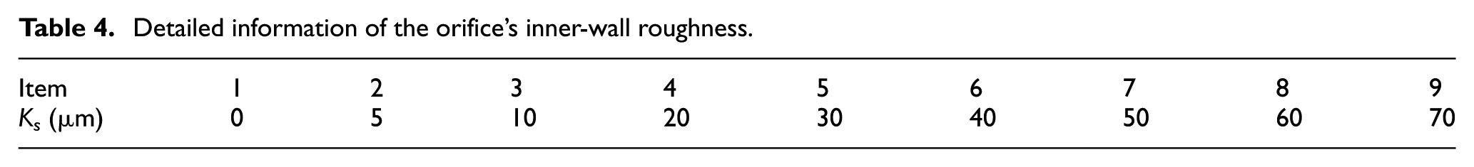
The detailed information of the orifice’s inner-wall roughness is shown in Table 4, and the contour distribution of physical parameters under different Ks is shown in Figure 8. With diameter d2 = 2 mm, the variation of the inner-wall roughness from 0 to 70 μm seems to have no effect on the static pressure and the vapor volume fraction.
Detailed information of the orifice’s inner-wall roughness.

Contour distribution of four physical parameters under different Ks.
From the analysis in Figure 8, roughening the inner wall can increase the drag force of the inner wall acting on the fluid flow and suppress the intensity of cavitation, which in turn enlarge the effective flow area of the fluid medium. The mass flow rate is the combined action result of the drag force and the cavitation, so the flow coefficient decreases sharply when Ks increased from 0 to 5 μm and almost remains constant when Ks increased from 5 to 70 μm, as shown in Figure 9(a). The flow coefficient is 0.865, 0.859, and 0.855 for d2 being 1, 2, and 3 mm, respectively. Enlarging d2 makes the effect of Ks on flow coefficient more notable, and the flow coefficient decreases by 0.67%, 0.40%, and 0.23% for d2 being 1, 2, and 3 mm with Ks increasing from 0 to 10 μm, respectively.

Variation of different physical parameters under different Ks: (a) flow coefficient and (b) vapor mass flow rate at the outlet.
Roughening the inner wall makes the fluid flow stay attached to the wall easier compared to the smooth wall and increases the drag force acting on the fluid flow, which in turn increases the quantity of the cavitation bubbles dissolving back into the fluid flow when the pressure recovers and the cavitation bubbles break. So, roughening the inner wall can suppress the onset of cavitation, and the vapor mass flow rate at the outlet decreases along with the increment in Ks. As shown in Figure 9(b), increasing Ks from 0 to 10 μm, the vapor mass flow rate decreases by 46.59%, 34.33%, and 29.31% for d2 being 1, 2, and 3 mm, respectively. The effects of the inner-wall roughness on the vapor mass flow rate are notable when the smoothed inner wall changed to the roughed inner wall, but the effect is not obvious when Ks increased from 10 to 70 μm. For the conical nozzles, it can be said that roughening the inner wall from a certain level to a more rough level leads to little effect of Ks on the vapor mass flow rate. The higher intensity of cavitation makes the effects of Ks on the vapor mass flow rate more notable.
Conclusion
In this article, the geometric parameters (ratio of orifice’s length to diameter, conical angle, and inner-wall roughness) of the conical nozzles are investigated to study the effect on the flow and cavitation characteristics with fluid medium being tap water via CFD method. The main conclusions are as follows:
The ratio of the orifice’s length to diameter: Prolonging orifice’s length hardly affects the distribution manner of the static pressure, but it increases the drag force of the inner wall acting on fluid flow, which in turn increases the quantity of the cavitation bubble breakage and the cavitation bubbles dissolving back into the fluid flow when the pressure recovers. Keeping the inlet pressure and diameter constant, although the variation of l2/d2 affects flow pattern inside nozzles, the flow coefficient remains constant for different d2 under different l2/d2. At the same pressure drop, enlarging d2 increases the intensity of cavitation inside nozzles, which in turn makes the effect of l2/d2 on cavitation characteristics more notable.
The conical angle: The variation of conical angle has notable effect on the gradient of the static pressure inside conical nozzles. Increasing the conical angle from 21.8° to 90° increases the gradient of the static pressure, which in turn increases the intensity of cavitation inside nozzles. Increasing β from 21.8° to 90°, the flow coefficient decreases linearly under different d2, and the slope is −0.00371. Enlarging d2 increases the intensity of cavitation inside nozzles, which in turn makes the effects of β on cavitation characteristics more notable.
The inner-wall roughness: Roughening the inner wall makes the fluid flow stay attached to the wall easier compared to the smooth wall. And roughening the inner wall increases the drag force acting on the fluid flow, which in turn decreases the quantity of the cavitation bubbles inside the fluid flow. So, roughening the inner wall can suppress the onset of cavitation. The decrement in flow coefficient is notable when Ks increased from 0 to 5 μm, but it remains almost constant when Ks increased from 5 to 70 μm. Increasing the intensity of cavitation inside nozzles makes the effect of Ks on cavitation characteristics more notable.
Footnotes
Appendix 1
Handling Editor: Roslinda Nazar
Declaration of conflicting interests
The author(s) declared no potential conflicts of interest with respect to the research, authorship, and/or publication of this article.
Funding
The author(s) disclosed receipt of the following financial support for the research, authorship, and/or publication of this article: This study was funded by the National Key Research and Development Program of China (2017YFB0306400), the National Natural Science Foundation of China (61672210), and the Henan Research Program of Foundation and Advanced Technology (162300410183).