
Abstract
Flow prediction, heat transfer pattern, and thermo-hydraulic efficiency in a heat exchanger tube fitted with vortex generator are chosen for the present research. The 30° inclined ring is opted to develop the performance of the heat exchanger tube. The effects of inclined ring configuration and placement in the heat exchanger tube on the patterns of flow and heat transfer are investigated. The Reynolds number (at the entry zone of the periodic model) in the range of around 100–2000 (laminar flow region) is discussed. The heat transfer ability, pressure loss, and efficiency of the heat exchanger tube fitted with 30° inclined ring are analyzed with the numerical method (finite volume method). The SIMPLE algorithm of the commercial code is picked for the present study. The simulated results in the heat exchanger tube fitted with 30° inclined ring are offered in patterns of streamlines, temperature contour, and Nusselt number contour. From the preliminary result, it is found that the creation model of the heat exchanger tube fitted with 30° inclined ring has sufficient reliance to measure flow and heat transfer profiles. The installment of the 30° inclined ring in the heat exchanger tube leads to greater heat transfer ability and thermo-hydraulic performance because of the creation of the vortex flow and thermal boundary layer disturbance on the heat exchanger tube surface. The heat transfer ability in the heat exchanger tube fitted with 30° inclined ring is found to be around 1.00–10.56 times above the plain circular tube. In addition, the installation of the 30° inclined ring in the heat exchanger tube gives the maximum thermal enhancement factor around 3.18.
Introduction
The effort to improve the thermal efficient for various kinds of heat exchanger devices has been found in many industries. The objectives for the improvement of the heat exchanger device are to increase the ability of heat transfer and also reduce the size of the heat exchanger machine. 1 The active and passive methods are picked to augment the heat transfer coefficient in the heat exchanger. The active technique is the increment in the heat transfer rate in the system by the additional power such as vibration. The passive technique is the installation of the vortex generators or turbulators such as conical ring, baffle, wing, winglet, and rib in the heat exchanger machine to produce the vortex flow which disturbs the thermal boundary regime of the heat transfer face. The perturbation of the thermal boundary layer is important reason for the improvements of the heat transfer ability and thermo-hydraulic performance. The passive technique reduces the operation cost of the heat transfer process. Therefore, the passive method is picked to expand the heat transfer ability and thermo-hydraulic efficiency for the present work.
The numerical and experimental examinations for the improvement of the heat exchanger by passive technique had been reported by many researchers. Nakhchi and Esfahani 2 numerically investigated on turbulent Cu–water nanofluid in heat exchanger tube (HET) installed with perforated conical ring on heat transfer ability and flow structures. They found that the heat transfer ability increases around 278.2% greater than the plain tube without conical ring with the top thermal performance around 1.10 when the perforated conical ring in the tube heat exchanger is installed. Nakhchi and Esfahani 3 also investigated the effects of the number of hole and hole diameter for the perforated conical ring in the tube. They informed that the heat transfer ability of the tube inserted with the conical ring reduces when the number of holes from 4 to 10 increases. They also aggregated that the optimum thermo-hydraulic performance is about 1.241. Ibrahim et al. 4 computationally tested heat transfer analysis in the heating device fitted with conical ring. The three different configurations of the conical ring, that is, convergent conical rings (CRs), convergent–divergent conical rings (CDRs), and divergent conical rings (DRs), were compared. They detected that the conical ring can enhance the heat transfer rate and thermal performance of the heat exchanger system. They reported that the average Nusselt number is around 330%, 419%, and 765% greater than the smooth tube, respectively, for CR, CDR, and DR. Mohammed et al. 5 claimed that the highest performance of the heat exchanger system is around 365% when the DR is inserted in the system. Sheikholeslami et al. 6 experimentally and numerically studied turbulent flow and heat transfer in a double-pipe air-to-water heat exchanger with conical ring. The effects of conical ring configuration, open area ratio, Reynolds number, conical angle, and pitch ratio on flow and heat transfer characteristics were considered. Sripattanapipat et al. 7 presented numerical investigation in the HET with hexagonal conical-ring inserts. They summarized that the V-shaped hexagonal conical rings perform higher Nusselt number than the typical conical ring.
The well-known vortex generators, which are always selected to expand heat transfer ability and thermal efficiency in the heat exchanger system, are baffle8–12 and rib13–18 type vortex producers. The installation of the baffle and rib in the heat exchanger devices gives high thermal performance and heat transfer ability when compared with the other kinds of the vortex generators or another passive technique. The boundary layer disturbance, turbulent fluid blending, and bounce flow on the heat transfer regime are phenomena in the heat exchanger device when the rib or baffle is installed in the heat transfer section.
The important factors, which are considered for the selection of the passive method, are vortex generator manufacture, installation, maintenance, and heat transfer ability of the vortex generator. From the previous research studies, it can be summarized that the prominent point of the rib/baffle is the high ability of heat transfer, while the advantage of the conical ring is uncomplicated forming, facile maintenance, and simple installation. In the present work, the combination between conical ring and baffle, which is called “inclined ring (IR),” is opted to enhance the ability of heat transfer for the HET. The IRs are inserted in the HET with the main aim to originate the vortex flow. The vortex flow, which is created by IR, may disturb the thermal boundary layer on the tube wall which is the cause for heat transfer and efficiency augmentations in the HET. The influences of the IR size and installing position in the HET on flow profile, heat transfer pattern, and performance are investigated numerically. The numerical study can support to explain the heat transfer and flow profiles in the HET. The understanding of mechanisms in the HET is a significant knowledge for the heat transfer ability. The measurements of the heat exchanger tube fitted with 30° inclined ring (HETIR) performance with the dimensionless variables are also shown.
Physical configuration
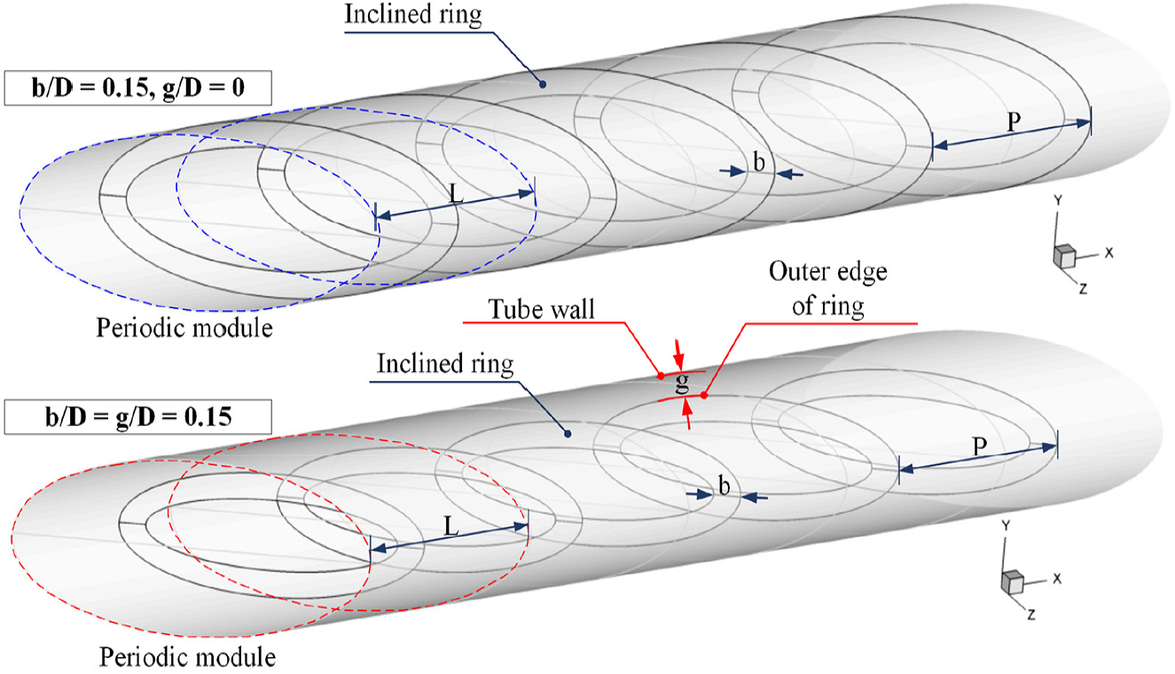
The dimension of the HET is referred from Jedsadaratanachai et al. 19 The numerical model for the current examination is an HETIR as shown in Figure 1. The diameter of the HET, D, is fixed around 0.05 m for all cases. The ratio between IR height, b, and the tube diameter or b/D is adjusted in the range of 0.05–0.25. The pitch distance ratio of the IR or P/H is fixed around 1. The gap distance between the outer edge of the IR and the tube wall, g, is varied; g = 0–0.30D. The inclination angle of the IR in the HET is around 30° in all cases.
HETIR.
The periodic domains of the HETIR at b/D = 0.15 and g/D = 0 and 0.15 are shown in Figure 2(a) and (b), respectively. The configuration of mesh for the HETIR is hexahedron. The fine mesh is adopted near the tube wall (boundary layer regime) of the HETIR. The number of mesh for the HETIR is around 120,000 in all examinations.

(a) Numerical domain for the HETIR at b/D = 0.15 for g/D = 0, (b) numerical domain for the HETIR at b/D = 0.15 for g/D = 0.15, and (c) boundary condition of the computational domain.
Numerical method and mathematical foundation
The steady state is set for flow characteristic in the HETIR. The heat transfer pattern in the HETIR is also counted as steady condition in three dimensions. The dimensionless variable for the air velocity is Reynolds number. The Reynolds number based on the tube diameter around 100–2000 (at the entry zone) is analyzed for the HETIR. The air is agreed as incompressible flow because the air has low velocity. The air has the Prandtl number around 0.707 (300 K). The thermal properties of the tested fluid are counted to be unabated at the average bulk mean temperature. The forced convection heat transfer is evaluated for this work, while the radiation and unforced convection are disregarded. The body force and viscous dissipation are also ignored. No slip wall identity is adopted for tube surface and IR. The periodic boundary, 20 both flow profile and heat transfer pattern, is applied for the entrance and outlet regions of the physical domain. The IR is approximated to be insulator or heat flux around 0 W m−2, while constant temperature state around 310 K is utilized for the tube wall. The boundary condition for the numerical model of the HETIR can be concluded as Figure 2(c).
The present numerical model of the HETIR is answered with the finite volume method (by commercial code). The SIMPLE algorithm of the commercial program is opted for the simulation process. The mathematical foundation of the present research is referred from Cengel and Ghajar 1 The significant equations for the simulation process are continuity, Navier–Stokes, and energy equations, which are demonstrated in equations (1)–(3), respectively. The continuity and momentum equations are discretized by the power law scheme, while the energy equation is discretized with QUICK scheme. The numerical solutions are measured to be converged when the normalized residual values are lesser than 10−5 all variables, but lightly than 10−9 for the energy equation.
Continuity equation
Momentum equation

Energy equation

where Γ is the thermal diffusivity and is written as follows

The dimensionless variable of the air velocity in the HETIR is presented in feature of the Reynolds number based on the circular tube diameter, D. The Reynolds number can be computed as equation (5)

The dimensionless term for the pressure drop of the HETIR is reported in feature of friction loss or friction factor. The friction factor can be defined from equation (6)

The heat transfer ability in the HETIR is concluded in terms of the local Nusselt number (Nux) and average Nusselt number (Nu) as equations (7) and (8), respectively

The thermo-hydraulic efficiency of the HETIR is calculated in mode of thermal enhancement factor (TEF) as equation (9),21,22 The TEF for the HETIR is defined as the ratio of the heat transfer coefficient of an improved device, h, to that of a plain surface, h0, at similar pumping power
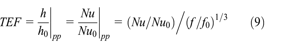
The Nu0 and f0 in equation (9) are the average Nusselt number and friction loss values for the plain tube, respectively.
Verification of the simulation
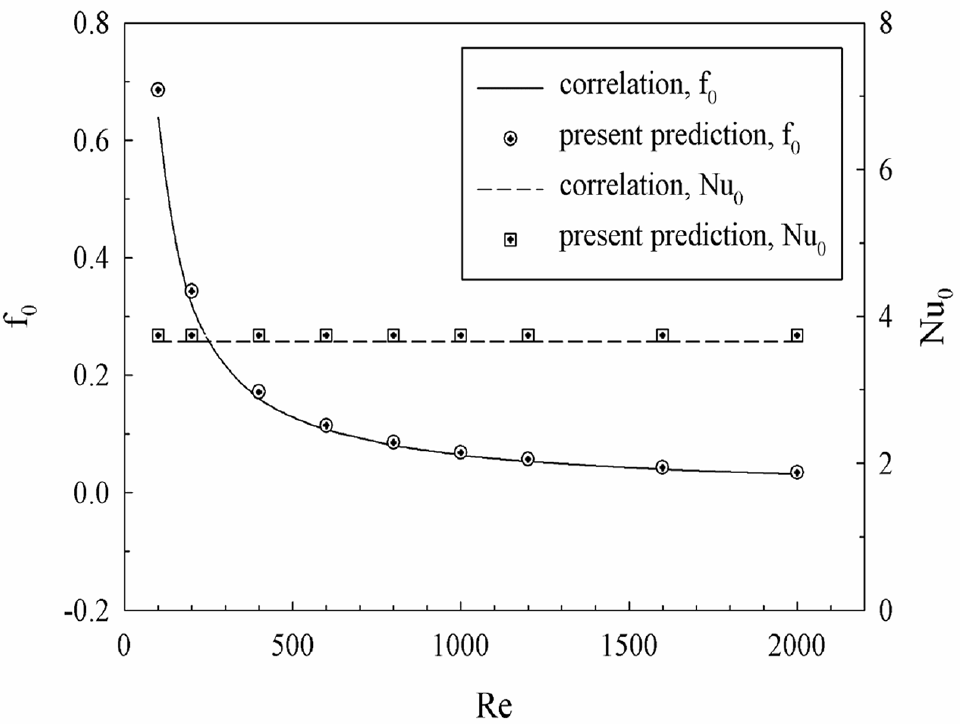
The physical model of the HETIR is checked before the simulation process. The modeling check is an important part to enhance credibility of the numerical results. The plain tube verification (both Nu and f) and grid independence are numerical validation of the HETIR model. The verification of the plain tube is performed by relating the simulated results with the values from the correlations, 1 both Nusselt number and friction loss. Figure 3 reports the plain circular tube validation for the current work on Nusselt number and friction loss. It is found that the deviations of heat transfer and pressure loss are within ±10% in all flow velocities.
Numerical validation: plain tube verification.
The physical models of the HETIR are compared at various grid cells: 80,000, 120,000, 180,000, 240,000, and 300,000, as shown in Figure 4. As depicted in the figure, the increment in the grid cell higher than the 120,000 cells has no impact for both heat transfer ability and pressure drop. Therefore, the number of grid cell of about 120,000 is utilized for all examined cases of the HETIR. The appropriate number of grid cell for the HETIR can save time for simulation process and also give the high precision result. From the preliminary investigation in this part, it can be concluded that the physical domain of the HETIR has sufficient reliance to forecast flow figure and heat transfer profiles of the HETIR.

Numerical validation: grid independence.
Simulated result and discussion
The patterns on heat transfer and flow in the HETIR are reported in the form of streamlines, temperature contour, and local Nusselt number contour. The dimensionless variables on heat transfer ability and pressure drop of the HETIR are concluded in features of Nusselt number ratio (Nu/Nu0) and friction factor ratio (f/f0), respectively, while the dimensionless variable for the efficiency of the HETIR is reported in form of TEF.
Mechanisms in the HETIR
The separation of the mechanisms in the tested section is referred from Jedsadaratanachai. 19 The mechanisms in the HETIR can split into two sections: heat transfer profile and flow topology. The heat transfer structure relates with the flow pattern in the HETIR; therefore, the variation of the flow pattern, when parameters of the HETIR are varied, affects the heat transfer ability.
Figure 5 displays the longitudinal vortex flow in the HETIR at b/D = 0.15, g/H = 0, and Re = 600. From the figure, it can be seen that the IR can build the vortex flow that impinges on the tube wall. The impinging of the flow on the heat transfer surface is the disruption of the thermal boundary layer. The thermal boundary layer perturbation is the motive for heat transfer ability and thermal performance extensions in the HET. The vortex flow in the HET also assists a better fluid mixing. The better fluid mixing in the HET is another cause for the improvements of heat transfer rate and thermal performance.

Longitudinal vortex flow in the HETIR at b/D = 0.15, g/D = 0, and Re = 600.
The longitudinal vortex flow in the HET is also seen in the case of b/D = g/D = 0.15 as depicted in Figure 6. The flow can be separated into two parts: (1) flow among the outer border of the IR and tube wall (Figures 6(a)) and (2) flow inside the inner edge of the IR (Figure 6(b)). The gap distance among the outer border of the IR and the tube wall may help a preferable fluid merging, but reduce the strength of the main vortex flow. The optimum gap spacing may give the maximum TEF in the HETIR.
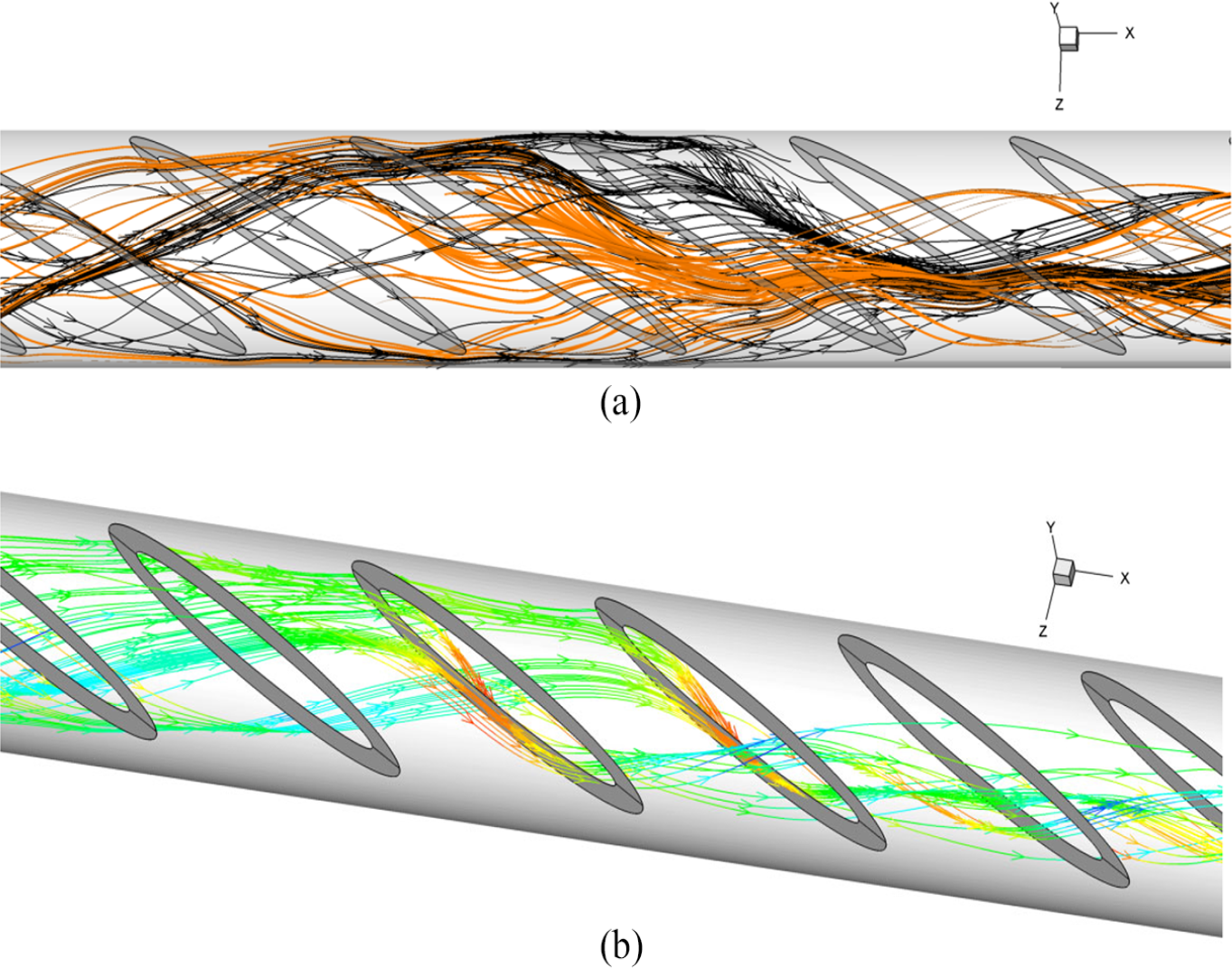
Longitudinal vortex flow in the HETIR at b/D = g/D = 0.15 and Re = 600 for (a) flow between the outer border of the IR and tube wall and (b) flow inside the inner border of the IR.
Streamlines in y–z plane of the HETIR is depicted in Figure 7(a)–(g), respectively, for g/D = 0, 0.05, 0.10, 0.15, 0.20, 0.25, and 0.30 at b/D = 0.15 and Re = 600. In general, the IR can create the vortex flow through the tested section in all investigated cases. The two main vortex flows (vortex1) with symmetry configuration at the upper–lower sections are found in the case of g/D = 0. The small vortices (vortex2) near the tube wall are seen when g/D > 0. The small vortices are found to be larger when g/D value is increased. The variation of the flow structure in the HETIR is concluded as Figure 8. The increment in the number of the vortex flow may benefit to increase the heat transfer ability and performance due to the better air mixing. But, the heat transfer ability and thermal performance may decrease because of the reduction in the vortex strength when the amount of the vortex flow is increased. The reduction in the vortex strength has direct effect on the thermal boundary layer disruption.

Streamlines in y–z planes in the HETIR at b/D = 0.15 and Re = 600 for (a) g/D = 0, (b) g/D = 0.05, (c) g/D = 0.10, (d) g/D = 0.15, (e) g/D = 0.20, (f) g/D = 0.25, and (g) g/D = 0.30.

Change of flow for the HETIR at b/D = 0.15 and Re = 600.
The temperature distribution in y–z plane of the HETIR is a descriptor to view the variation of the thermal boundary layer. Figure 9(a)–(g) reports the temperature contours in transverse planes for the HETIR of b/D = 0.15, g/D = 0, 0.05, 0.10, 0.15, 0.20, 0.25, and 0.30, respectively, at Re = 600. In general, the blue color (cold air) is found at the plane core, while the red color (hot air) is detected near the tube wall for the plain tube with no IR. The installation of the IR in the tested tube leads to the change of the thermal boundary layer. The better fluid blending is found when the IR is inserted in all studied cases. The layer of high temperature fluid near the tube wall decreases, while the low temperature fluid distributes from the core to the tube wall. The variation of the thermal boundary layer is found due to the impingement of the vortex flow on the heat transfer surface. The impingement position on the heat transfer surface is not in similar regime when the g/D value is changed (see Figure 10). The thermal boundary layer disruption can be considered from the thickness of the red layer of the hot fluid. The reduction in the hot fluid layer leads to the increment in the local heat transfer coefficient.

Temperature distributions in y–z planes in the HETIR at b/D = 0.15 and Re = 600 for (a) g/D = 0, (b) g/D = 0.05, (c) g/D = 0.10, (d) g/D = 0.15, (e) g/D = 0.20, (f) g/D = 0.25, and (g) g/D = 0.30.
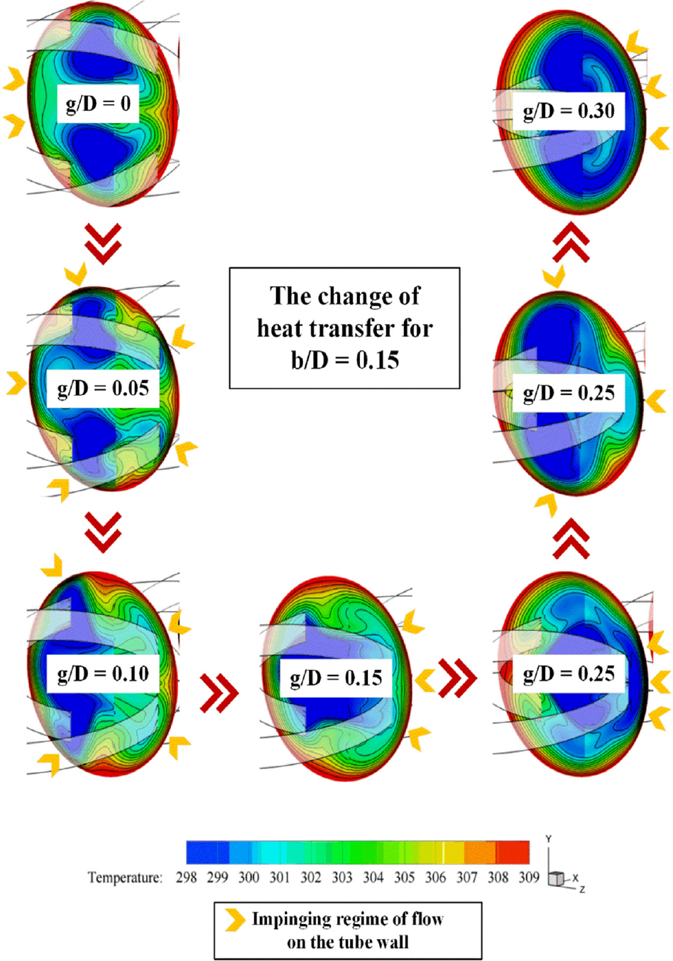
Change of heat transfer for the HETIR at b/D = 0.15 and Re = 600.
The specification of the tube side is depicted in Figure 11. The bounce of the air flow on the HET wall can also be considered from the local Nusselt number distribution as shown in Figures 12–16, respectively, for b/D = 0.05, 0.10, 0.15, 0.20, and 0.25 at Re = 600.
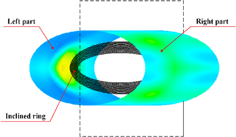
Tube wall description.

Local Nusselt number distributions in the HETIR at b/D = 0.05 and Re = 600.

Local Nusselt number distributions in the HETIR at b/D = 0.10 and Re = 600.

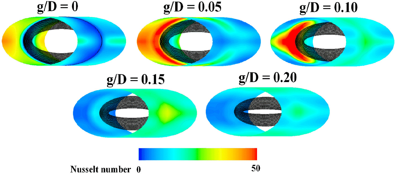
Local Nusselt number distributions in the HETIR at b/D = 0.15 and Re = 600.

Local Nusselt number distributions in the HETIR at b/D = 0.20 and Re = 600.
Local Nusselt number distributions in the HETIR at b/D = 0.25 and Re = 600.
For b/D = 0.05, the maximum of heat transfer regime is seen at the left pat of the HETIR for g/D = 0. This means that the b/D = 0.05 at g/D = 0 can produce the longitudinal vortex flow which extremely impinges on the left part of the HETIR. The local Nusselt number at the right part of the HETIR tends to increase when g/D value increases, while the local Nusselt number at the left part is viewed to be in the opposite trend. The HETIR at b/D = 0.10 performs nearly trend of the heat transfer ability as the case of b/D = 0.05, but the local Nusselt number at the right part of the HETIR decreases when g/D > 0.25.
For b/D = 0.15, the local heat transfer coefficient at the left part of the HETIR enhances when the g/D value increases, but decreases when g/D > 0.10. The IR with g/D = 0.20 provides the highest heat transfer ability at the right part of the HETIR. For easy consideration, the local Nusselt number distribution of the HETIR for left and right parts is plotted as an example in Figure 17(a) and (b), respectively.

Local Nusselt number distributions in the HETIR at b/D = 0.15 and Re = 600 for (a) left part of the HETIR and (b) right part of the HETIR.
For b/D = 0.20, the local Nusselt number at the left side of the HETIR augments when g/D value increases, but reduces when g/D > 0.10. The greatest local heat transfer coefficient at the right side of the HETIR is found at g/D = 0.20.
For b/D = 0.25, the greatest heat transfer ability at the left side of the HETIR is detected at g/D = 0.05–0.10, while the highest local Nusselt number at the right side of the HETIR is found at g/D = 0.15. In all b/D values, the heat transfer pattern has changed due to the variations of the flow profile and vortex strength in the HETIR when the g/D value is changed.
Performance analysis
The advantage of the IR in the HET cannot be discussed by heat transfer and flow profiles as in the previous part. Therefore, the pressure loss, heat transfer, and thermo-hydraulic performance in the HETIR are plotted with numeric value in this part.
Figure 18(a)–(e) presents the variation of the Nu/Nu0 with g/D at various Reynolds numbers for b/D = 0.05, 0.10, 0.15, 0.20, and 0.25, respectively. Generally, the heat transfer ability enhances when the Reynolds number increases in all b/D values. The Re = 100 lets the lowest heat transfer ability, while the Re = 2000 offers the reversed result. The insertion of the IR in the HET aids to improve the heat transfer ability higher than the plain circular tube with no IR in all cases (Nu/Nu0 > 1). The presence of the IR in the HET brings higher heat transfer ability than the plain tube around 1.00–3.33, 1.04–6.98, 1.20–7.55, 1.32–9.04, and 1.59–10.56 times, respectively, for b/D = 0.05, 0.10, 0.15, 0.20, and 0.25. The peak of Nusselt number ratio is found at g/D = 0.30, 0.25, 0.05, 0.05, and 0.05, for b/D = 0.05, 0.10, 0.15, 0.20, and 0.25, respectively, when considered at Re = 2000.

Nu/Nu0 versus g/D of the HETIR for (a) b/D = 0.05, (b) b/D = 0.10, (c) b/D = 0.15, (d) b/D = 0.20, and (e) b/D = 0.25.
The relation of the f/f0 with g/D at different Re values for the HETIR is plotted in Figure 19(a)–(e), respectively, for b/D = 0.05, 0.10, 0.15, 0.20, and 0.25. In general, the insertion of the IR in the tested section not only increases heat transfer ability, but also raises pressure drop. The friction loss of the HETIR is higher than the plain circular tube in all investigated cases (f/f0 > 1). The friction loss tends to extend when the Reynolds number for all b/D values increases. The Re = 100 gives the lowest friction loss, while the Re = 2000 performs the adverse trend. The f/f0 is around 1.00–4.55, 1.13–10.77, 1.79–20.56, 1.36–33.11, and 4.97–59.95 for the HETIR at b/D = 0.05, 0.10, 0.15, 0.20, and 0.25, respectively. Considering at Re = 2000, the peak of the friction loss is seen at g = 0.15D, 0.10D, 0.10D, 0.10D, and 0.05D for the HETIR with b/D = 0.05, 0.10, 0.15, 0.20, and 0.25, respectively.

f/f0 versus g/D of the HETIR for (a) b/D = 0.05, (b) b/D = 0.10, (c) b/D = 0.15, (d) b/D = 0.20, and (e) b/D = 0.25.
The variation of TEF with the g/D at various Re values for the HETIR at b/D = 0.05, 0.10, 0.15, 0.20, and 0.25 is plotted in Figures 20(a)–(e), respectively. Due to the installation of the IR in the HET expands both heat transfer ability and pressure drop, the TEF is opted to discuss the thermo-hydraulic performance of the HETIR by considered at similar pumping power. In most cases, the IR aids to develop the thermal performance of the HET greater than the plain tube with no IR (TEF > 1). The IR in the HET with b/D = 0.05, 0.10, 0.15, 0.20, and 0.25 gives the TEF around 0.85–2.12, 0.78–3.18, 0.77–3.06, 0.76–2.92, and 0.81–2.76, respectively. The best TEF is detected at g/D = 0.30, 0.25, 0.05, 0.05, and 0.10, respectively, for the IR with b/D = 0.05, 0.10, 0.15, 0.20, and 0.25 when considered at Re = 2000.

TEF versus g/D of the HETIR for (a) b/D = 0.05, (b) b/D = 0.10, (c) b/D = 0.15, (d) b/D = 0.20, and (e) b/D = 0.25.
Conclusion
Numerical forecasts on heat transfer ability, flow structure, and thermo-hydraulic performance in the HETIR are reported. The influences of the IR size and installed position on flow pattern and heat transfer profile are investigated for the laminar flow portion of the Reynolds number about 100–2000. The main pronouncement for the present exploration can be summarized as follows.
The simulated results can aid to explain the heat transfer and flow profiles in the HETIR. This knowledge is a significant data which assists to raise the ability of heat transfer in the HET. The comprehension on heat transfer and flow structures in the HET also promotes the new design of the compact HET.
The installation of the IR in the HET can develop both heat transfer ability and thermo-hydraulic performance. The heat transfer ability and performance grow because of the thermal boundary layer disruption. The better air blending in the HET is another cause for heat transfer rate and thermal performance extensions. The presence of the IR in the HET also grows pressure loss, especially, at high Re and b/D values.
In the range studies, the heat transfer rate and pressure loss in the HETIR are around 1.00–10.56 and 1.00–59.95 times above the plain circular tube with no IR, respectively. The TEF is found to be around 0.76–3.18 depending on Re, b/D, and g/D values.
The variability of the heat transfer and flow schemes is obviously met when the parameters of the HETIR are differed, especially, gap distance. The suggestion gap spacing of the IR in the HET is around 0.30D, 0.25D, 0.05D, 0.05D, and 0.10D, respectively, for the b/D = 0.05, 0.10, 0.15, 0.20, and 0.25 when considered at TEF value.
The HET inserted with the IR gives nearly value of thermal performance when compared with the HET inserted with V-shaped baffle. 18 The production, maintenance, and installation of the IR in the HET are easier than the V-shaped baffle.
Footnotes
Appendix 1
Acknowledgements
The authors would like to thank Associate Professor Dr Pongjet Promvonge for suggestions.
Handling Editor: James Baldwin
Declaration of conflicting interests
The author(s) declared no potential conflicts of interest with respect to the research, authorship, and/or publication of this article.
Funding
The author(s) disclosed receipt of the following financial support for the research, authorship, and/or publication of this article: This research was funded by King Mongkut’s University of Technology North Bangkok, Contract no. KMUTNB-63-KNOW-010.