
Abstract
A magnetorheological fluid damper is a device in which a magnetorheological fluid is filled in a damper. In this device, the magnetic field is controlled by an external current (voltage) so that the magnetic force of a piston inside the damper changes like an electromagnet. The damping force of the damper is controlled by changing the magnetic force of the piston. With the increasing magnetic force of the piston, the viscosity of the magnetorheological fluid in the damper increases. The primary aim of this study was to maximize the magnetic flux density and identify the following influencing factors from the relevant literature: piston and outer tube materials, piston length, piston diameter, cylinder wall thickness, damper channel clearance, gap channel length, current, and magnetorheological fluid. A magnetic circuit analysis was performed using ANSYS Maxwell, and the optimal parameter combination was identified using the Taguchi method. The analysis of variance was used to examine the influence of various factors on quality characteristics. This study helps understand the relation between structure size, material, and magnetic flux density and contributes to future generations of magnetorheological fluid damper design analysis.
Keywords
Introduction
A magnetorheological fluid (MRF) is a new type of intelligent fluid. The characteristics of the MRF can change from those of a Newtonian fluid to those of a Bingham fluid instantaneously (milliseconds) after low energy consumption. A magnetic field can change the type and viscosity of the MRF. MRF particles are magnetized to produce a linear chain, and the corresponding drop strength can be obtained with the changing magnetic field, thereby changing fluidity. If the magnetic field is eliminated, the characteristics of the MRF will return to those of the Newtonian fluid. When the MRF does not apply a magnetic field, a certain damping force is observed because of the nature of magnetic particles and a carrier liquid. If the applied magnetic field gradually increases, the damping force continues to increase until magnetic saturation is relatively slow and does not increase. 1 MRF magnetization is unaffected by temperature, and thus the MRF is relatively insensitive to temperature ranging from −40°C to 130°C; however, the increasing temperature leads to an evaporation of the carrier liquid and reduces MRF viscosity. 2
The MRF damper is categorized into three design modes: (1) the first mode, where two pressure-type magnetic pole plates are relatively fixed, the applied magnetic field is perpendicular to pressure, the pressure direction is parallel to the magnetic pole plate, and the MRF between the two magnetic pole plates is pressurized to flow; (2) the second mode, where the direction of the shear-type damper is parallel to the two pole plates and in relative motion and the direction of the applied magnetic field is perpendicular to that of displacement so that the MRF between the magnetic plates is subjected to shear stress; and (3) the third mode, where the magnetic field and force are added by the squeeze type, the displacement direction is perpendicular to the two pole plates, and the MRF is squeezed (Figure 1). 3

Three design modes of the MRF damper: (a) pressure type, (b) shear type, and (c) squeeze type.
H and B are the magnetic field strength (A/m) and magnetic flux density (or shear stress intensity) (T), respectively. A magnetic field constant is the ratio of magnetic flux density to magnetic field strength in vacuum. 4 M, S, N, I, L, HL, and IN are the magnetic permeability, cross-sectional area, number of turns of the coil, current drawn into the coil, magnetic path length, magnetic pressure drop, and magnetomotive force, respectively.
The formulas of magnetic flux density B and magnetic flux Φ are as follows


A Herschel–Bulkley (HB) model represents the relation between the shear stress and shear strain rates for non-Newtonian fluids. 5 Equation (4) presents the HB model

where

Combination of the Bingham and power law characteristics in the HB fluid model.
Jolly et al. established a one-dimensional model to evaluate the mechanical and magnetic properties of MRFs. When an MRF is influenced by the magnetic field, the strain is less than the yield point; the fluid is in a state of non-linear elastic solids; and the MRF has a modulus of elasticity. 6
Ginder et al. used a non-linear finite element method to calculate magnetic field distribution in the magnetizable particle chain and the attractive force between the particles induced by a magnetization saturation effect, thereby predicting the shear stress corresponding to the magnetic field. 7
Kanno et al. experimented with three magnetic particles having a diameter of approximately 3.7 μm and the volume percentages of 0.1, 0.2, and 0.3. The final result showed that MRF magnetic susceptibility was proportional to the increasing volume percentage, and the magnetic field strength of the MRF saturated at 250 kA/m. When the magnetic field strength was continuously increased, the magnetic flux density slightly increased, indicating that the magnetic field strength and volume percentage are not correlated. 8
The Bingham plastic constitutive model is widely used to predict the characteristics of electromagnetic rheological fluids (electrorheological fluids (ERFs) and MRFs) after lodging. However, these fluids have been shear thinned or shear thickened, and the Bingham model cannot accurately predict the characteristics of the factor because the post-yield plastic viscosity is assumed to be constant. Wang and Gordaninejad 9 demonstrated through theory and experiment that the HB fluid model can successfully predict the non-Newtonian fallout characteristics of the ERF and MRF.
Dogrouz et al. established two types of MRF dampers. In one type, a heat sink was placed adjacent to the MRF damper of an automobile, and the other type had no heat sink. The installed heat sink effectively improved heat dissipation and increased the damping force. 10
Li and Zhang 11 found that the friction generated by magnetic particles induces one-third of the total shear stress, which validates the influence of the MRF on the friction force.
Lambropoulos et al. studied the changes in shear stress and normal stress between an MRF and a borosilicate glass interface at different currents and calculated a mathematical formula to convert shear modulus G to Young’s modulus E. The MRF comprised 45% carbonyl iron powder. A current of 15 A was applied to the MRF, and the shear stress was 0.05 MPa, which was magnetically saturated. 12
In 2017, Ghorbanpour Arani et al. proposed a closed-form solution for free vibration analysis of coupled magnetorheological sandwich beams under a simple boundary condition. The results show that the modal loss factor is different from the natural frequency and is reduced by increasing the magnetic field strength. 13 They studied the free vibration analysis of intelligent sandwich panels based on Winkler–Pasternak foundation. They observed that increasing the volume fraction of carbon nanotubes (CNTs) in the panel leads to an increase in the stability of the ER sandwich panel. 14 In 2018, they studied the vibration analysis of viscoelastic sandwich panels bonded to the Pasternak foundation. The results of the module show that increasing the thickness ratio of the core to the panel results in a decrease in the natural frequency because the MRF core is softer than the nanocomposite panel. 15 In 2019, they studied semi-active control of sandwich panels with electrorheological (ER) cores and CNT-reinforced composite panels using intelligent ER dampers. 16
Research methods
Processing using Maxwell 2D electromagnetic field analysis in this study involved a preprocessing module, an analysis module, and a post-processing module. The procedure included various steps such as building models, determining material settings, determining boundary conditions and loads, solving, and post-processing. Because the damper model is symmetric and the Y-axis is used as a symmetry axis, a half-edge model analysis can be performed to reduce the analysis time. Model design parameters were piston length, piston diameter, wall thickness, damper channel clearance, and clearance channel length (Figure 3). Figure 4 shows a partially enlarged view of the gap channel, where five points indicate analysis positions.
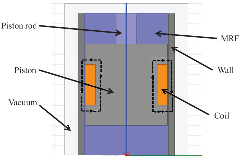
Schematic of the internal structure of the MRF damper.

Damper channel clearance.
Material setting
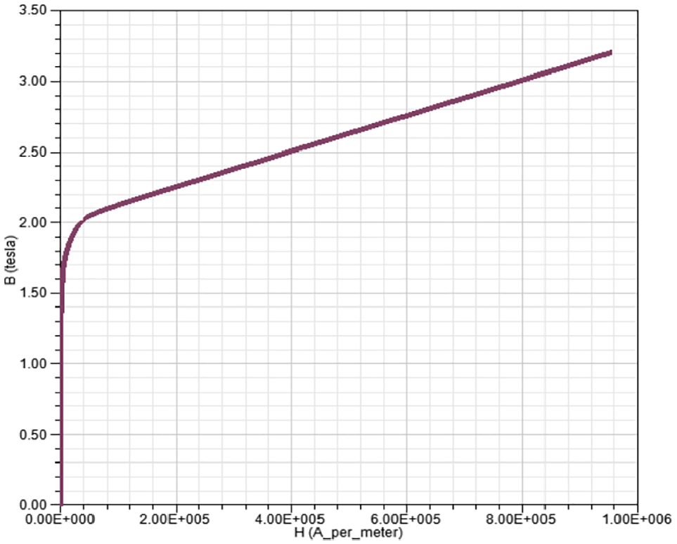
The damper sleeve is filled with the MRF, and the piston is a force-receiving part. The material must have specific strength. To induce the MR effect of the MRF inside the gap in order to generate shear stress, high magnetic permeability, and magnetic flux density, soft magnetic materials, such as low-carbon steel, must be selected. Therefore, two low-carbon steel materials, AISI1008 and AISI1010, were selected in this study. Figures 5 and 6 present the magnetic field and magnetic flux changes. The piston rod is used to withstand the external force and not operated in the magnetic circuit. Therefore, stainless steel is used for fabricating the piston rod.

AISI 1008 B–H curve.
AISI 1010 B–H curve.
The MRFs used were MRF-122EG, MRF-132DG, and MRF-140CG of the LORD Company. The carrier fluids of the three MRFs are hydrocarbons. The density and viscosity, magnetization curve, and magnetic field strength for these three MRFs are different. Moreover, the corresponding lodging stress is also different. Figures 7–9 present the magnetization curves, which are also called B–H curves or hysteresis curves, of the three MRFs, indicating the relation between the magnetic field and the flux change of the MRF. When the applied current increases the magnetic field strength (H). When the MRF is magnetized, the magnetic flux density (B) correspondingly increases. If the magnetic field strength (H) reaches a particular intensity and the magnetic flux density (B) increases very slowly, it generally represents a state of magnetic saturation. Because the inside of the cylinder is vacuum, setting the boundary condition for the vacuum outside is essential.
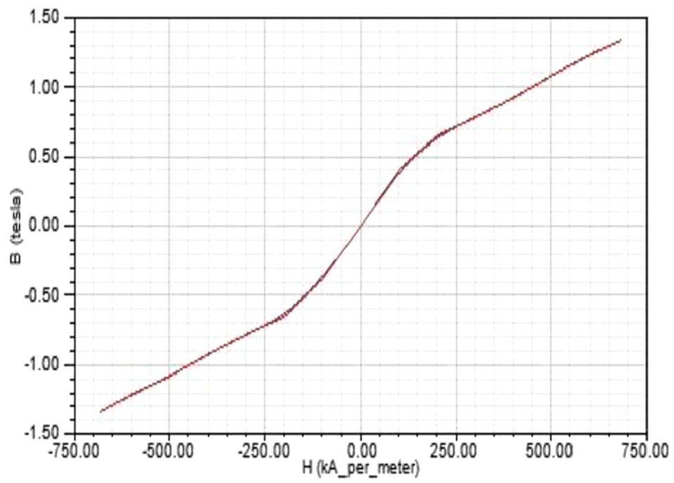
MRF-122EG B–H curve.

MRF-132DG B–H curve.
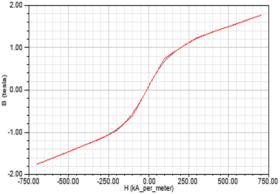
MRF-140CG B–H curve.
Boundary condition setting and load setting
Because the MRF is operated under vacuum (the magnetic permeability of vacuum is 1), establishing a vacuum boundary condition around the structure of the analysis is essential. The coil material is copper, and the magnetic permeability of copper is 0.9999 (∼1). The number of turns of the coil is 400, and the copper wire diameter is 0.3 mm. The copper wire is wound on the piston, and currents of 0.5, 1, and 1.5 A are supplied. The magnetic field inside the coil is directed from the S pole to the N pole and that on the outside of the coil is directed from the N pole to the S pole. Figure 3 shows the load direction of the spiral coil.
Taguchi method
In this study, the Taguchi method was used to determine the degree of influence of the internal structure size of the damper. The basic steps of the Taguchi method are as follows: (1) selecting a control factor and level; (2) selecting a suitable orthogonal table for less experiment, where the number of times was obtained for all experiments; and (3) analyzing quality characteristics, the S/N ratio, and the variation number to determine the optimal parameter combination. In this study, L18 (21 × 37) was selected as the orthogonal table for data collection.
Magnetic field strength analysis results
The magnetic field strength of the MRF saturated at 250 kA/m. If the magnetic field strength continuously increased, the magnetic flux density increased slightly. The excitation current of this section examined the magnetic saturation of the MRF and evaluated whether the magnetic field strength was less than 250 kA/m.
According to the parameters corresponding to 18 groups of a Taguchi straight-through table, 18 sets of MRF damper designs were drawn. For example, the magnetic field intensity distribution of No. 1 in Figure 10 indicates that the permeability of low-carbon steel is higher than that of the MRF. Magnetic permeability induces a magnetic pressure drop in the gap channel. Moreover, with the increasing magnetic pressure drop, the magnetic field strength increases, the magnetic field strength diagram of No. 1 indicates that, for the MRF in the cylinder, the channel gap had the highest magnetic field strength, and the magnetic field strength of the outer cylinder, piston, and other MRFs was low. Figure 11 presents the gap magnetic field strength distribution of 18 sets of experiments. The X-axis represents the distance from the outer circumference of the piston to the coil, and the Y-axis represents the magnetic field strength. When the MRF entered the channel gap, the magnetic field strength at the inlet was instantaneous. The shorter distance from the coil corresponded to the higher magnetic field strength, whereas the greater distance corresponded to the lower magnetic field strength. The magnetic field strength of the damper channel gap was less than the normal working range of 250 kA/m in the 18 sets of experiments.

Magnetic field strength for No. 1.

Distribution of 18 gap magnetic field strengths.
Magnetic flux density analysis results
Similarly, taking the magnetic field intensity distribution of No. 1 as an example, the influence factor of the magnetic flux density is in the order of the damper outer cylinder > piston head > channel gap, as shown in Figures 12 and 13. Because the magnetic permeability of low-carbon steel is higher than that of the MRF, a magnetic pressure drop was observed in the gap channel. The larger magnetic pressure drop corresponded to higher magnetic field strength and higher magnetic flux density. Figure 14 presents the distribution of gap flux density in the 18 sets of experiments. The X-axis represents the distance from the outer circumference of the piston to the coil, whereas the Y-axis represents the magnetic flux density. When the MRF entered the channel gap, the magnetic flux leakage phenomenon went offline. The shorter distance from the coil corresponded to the higher magnetic field strength, whereas the greater distance from the magnetic field corresponded to the lower magnetic induction strength.

No. 1 magnetic flux density.

No. 1 magnetic flux density vector.

Distribution of gap flux density in 18 groups.
Optimal S/N ratio and quality characteristics of the Taguchi method
As shown in Table 1, the experimental results of the three rows on the right are as follows: (1) the average of the magnetic flux density (quality characteristics) of each group; (2) SD, which is the standard deviation; and (3) the S/N ratio of the large characteristic formula. n and yi are the number of experiments in each group and data of each group of experiments, respectively. The S/N ratio of each experiment is calculated using formula (5).

Damper gap B field data of each group.

SD: standard deviation.
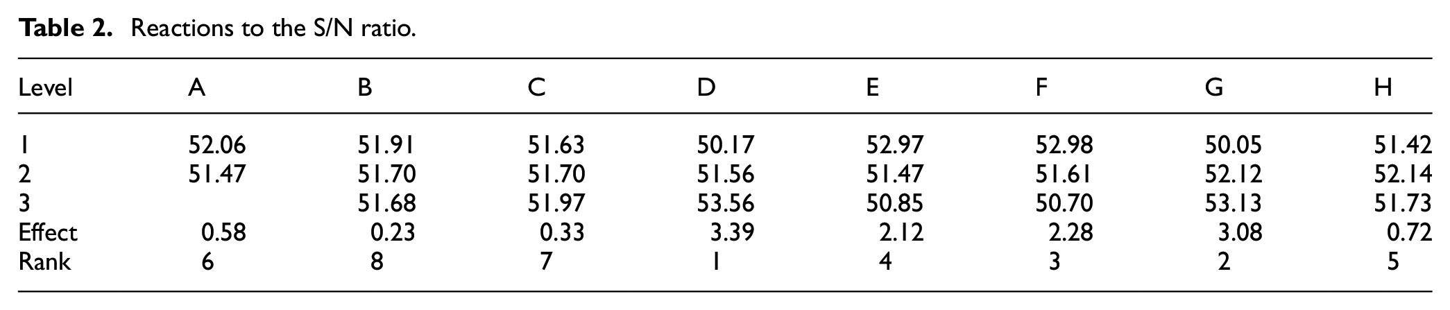
The S/N ratio reaction value of each factor at each level was calculated from Table 1. The factor response table and factor reaction diagram of the S/N ratio were obtained. The larger S/N ratio corresponded to the higher quality and stability. The factor effect analysis in Table 2 and Figure 15 indicates that the higher reaction value corresponded to the stronger influence of the factor on the experiment, and the response value was the difference between the maximum and minimum values of the factor. The S/N ratio response values of D (bar wall thickness), E (channel gap), F (gap channel length), and G (current) were 3.39, 2.12, 2.28, and 3.08 dB, respectively. These four factors in S/N are more influential than the reaction, and the optimal combination was A1B1C3D3E1F1G3H2.
Reactions to the S/N ratio.

Factor response diagram of the S/N ratio.
The optimal parameter combination indicated that, based on the size limit of the damper, the higher outer cylinder thickness (D) corresponded to the high magnetic flux density. Although current (G) was one of the factors influencing the magnetic flux density, the influence of the outer cylinder thickness was higher than that of the applied current.
The damper coil in the S/N analysis was wound around the piston, and the working channel gap is equal in two lengths. Because the coil was placed inside the sleeve, the MRF could participate in the magnetic circuit and the performance of the MRF could be effectively utilized. The magnetic flux density averaged to approximately 790 mT over an effective working gap length. Figure 16 presents the S/N gap flux density distribution.

S/N gap magnetic flux density distribution map.
Quality characteristic response values of each factor at each level can be calculated from Table 1. The factor response table and factor reaction diagram of the quality characteristics could be obtained. Table 3 and Figure 17 indicate that the higher quality corresponded to the higher stability. The quality characteristic response values of bar wall thickness (D), channel gap (E), gap channel length (F), and current (G) were 163.1, 102.4, 107.3, and 141.2 mT, respectively. These four factors in the quality characteristics of the reaction were more influential. The optimal combination was A1B2C3D3E1F1G3H2. The coil of the mean analysis damper was wound around the piston groove. Conclusion is primarily the same as that for the S/N damper. However, because the length of the piston was slightly elongated, the magnetic flux density of the working channel gap decreased slightly. The magnetic flux density averaged to approximately 760 mT over an effective working gap length. Figure 18 presents the mean gap flux density distribution. Table 4 presents two sets of magnetic flux density data sheets.
Factor response table for quality characteristics.

Two sets of magnetic flux density data sheets.


Factor response diagram for quality characteristics.

Mean gap flux density distribution.
Conclusion
For the structural design of the MRF damper, to efficiently use the magnetic properties of the MRF for establishing a set of analysis procedures, the following points are summarized:
The results from the quality response diagram and quality response table indicate that the influence of the outer cylinder thickness was higher than that of the input current. The outer cylinder operated as a yoke in the entire magnetic circuit loop and reduced magnetic flux leakage. Outward diffusion enhanced the efficiency of induction, with the effect of 5 mm thickness being the best.
The clearance channel on the piston must not be excessively long. Although a longer channel could increase the damping force, it could also considerably reduce the efficiency of applying the MRF. The lowest efficiency was observed for the appropriate channel length. The larger gap between the piston and the outer cylinder corresponded to lower magnetic flux density, and thus the model was designed to reduce the gap.
After obtaining the optimal parameter combination using the Taguchi method and analysis of variance, comparison verification should be performed for determining whether the structural size design of the set of parameters is the optimal combination.
Footnotes
Handling Editor: James Baldwin
Declaration of conflicting interests
The author(s) declared no potential conflicts of interest with respect to the research, authorship, and/or publication of this article.
Funding
The author(s) received no financial support for the research, authorship, and/or publication of this article.