
Abstract
This article presents a study on the transient dynamic responses of engagement process of one-way clutch using variable rectangular cross-section torsional spring, which is usually installed on the end of engine for preventing torque being transmitted back. A 2-degree-of-freedom torsional dynamic model is proposed in this article to study the engagement process of clutch under two conditions. Due to the variation of parameters, the torque transfer of the wrap–spring clutch during engagement is described by a multi-parameter equation. The torque transmitted by clutch during engagement process has been described by two phases, spring expanding and spring locking. Physical parameters of spring determining the torque during expanding are discussed. To verify the model, a dynamic experiment on clutch engagement is conducted.
Introduction
The one-way clutch usually applies in a variety of powertrain torsional system, such as air turbine starters, vehicle, and rotorcraft. 1 One-way clutch is also called overrunning clutch, which only transmits torque from the input to output. Different kinds of one-way clutch are distinguished by their torsional medium, such as roller, sprag, and wrap–spring. The one-way clutch has two working states that can be switched, engaging and overrunning.
As shown in Figure 1, the wrap–spring one-way clutch has a simple structure, which consists of the input and output housings, and wrap–spring, and characterized by lightweight, high reliability, durable, and high torque transmission. 2 The principle of wrap–spring clutch is presented in Figure 2. The direction of relative speed between input and output decides the clutch working condition. The spring is twisted and clutch transmits torque into the output when input speed is no less than the output. Otherwise, spring will release and produce slippage between input and output.

Three-dimensional sectional view of the wrap–spring clutch.

The structural schematic diagram of wrap–spring clutch.
Some researchers have studied the dynamics behavior of the one-way clutch in mechanical systems. Zhu and Parker1,3 used 2-degree-of-freedom (DOF) models to examine the nonlinear dynamics of a one-way clutch in serpentine belt system. Gill-Jeong 4 conducted research on the dynamic responses of one-way clutch in a single-pair spur gear system under different installation conditions. Ding and Zu 5 and Ding 6 evaluated the effect of a wrap–spring one-way clutch on the drive system of a two-pulley belt, considering the effects of different excitations and parameters on the dynamic response. Y Cao et al. 7 studied the steady-state response of the one-way clutch in the multi-clearance of the gear system and discuss the influence of moment of inertia and stiffness and damping on the system.
The engagement behavior of clutches has been concerned by many researchers. A Crowther et al. 8 developed a 4-DOF torsional system to investigate the clutch engagement judder and stick–slip in automotive powertrain systems. S Iqbal et al. 9 established a mathematic model based on extended reset-integrator friction model to understand the wet friction clutch engagement dynamics. L Li and R Singh 10 gave the numerical simulation of the nonlinear single-degree-of-freedom (SDOF) system during engine start-up process. The clutch dampers are described by a two-staged piecewise linear function of stiffness and damping. To understand the mechanism of friction clutch judder, L Li et al. 11 investigated the dynamic response characteristics of the clutch engagement process and find a simple and effective way to suppress the judder. P Vernay et al. 12 conducted an experimental study on the transient behavior of sprag clutch in the two modes of engagement mode and engaged mode. But the research of the clutch engagement is mainly about friction clutch; there is no research on the engagement behavior of the overrunning clutch; furthermore, no research has been performed yet for describing engagement process of wrap–spring clutch.
The torque is transmitted in a unique way when wrap–spring clutch is engaging. In order to achieve constant stress along with the spring, the coil cross-section is designed to vary exponentially as shown in Figure 3. Therefore, the spring coils carry an increasingly greater load along the spring. The engagement begins at the energizing coil which rotates with the holes in housings already. As the torque increases, the first active coil of the torque spring unwinds into the drum. As more torque is transmitted, more coils unwind into the drum until the drag torque is reached. The energizing coil carries a small amount of the torque to facilitate engaging, while each succeeding coil carries a proportionately larger share.
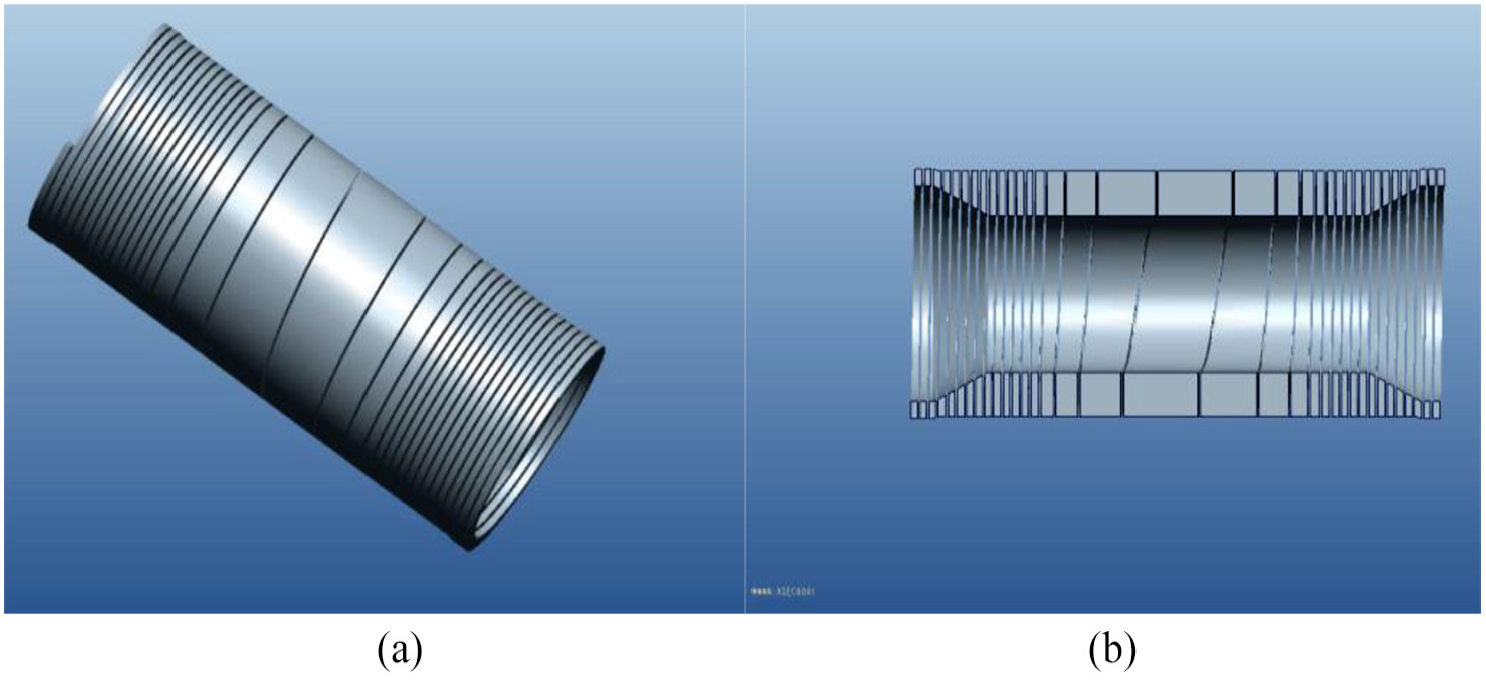
Three-dimensional model of variable rectangular cross-section torsional spring: (a) isometric view and (b) section view.
The purpose of this article is to study the dynamic behavior of the one-way clutch with a variable rectangular cross-section torsional spring in the engagement process. For this reason, the transfer torque model of the clutch is developed using the 2-DOF torsional dynamic model to represent the engagement process in section “Dynamic model of wrap-spring clutch engagement process.” In sections “Numerical simulations” and “Parameters effect,” the dynamic equations are solved numerically, and key structure parameters of clutch are analyzed by their effect on the dynamic behavior of the engagement process. In order to validate the model, the engagement experiment is performed on the test rig which has been established specially. The conclusions in this article can provide a theoretical basis for the design and use of this type of clutch in the future.
Dynamic model of wrap–spring clutch engagement process
Dynamic modeling
The process of wrap–spring clutch engagement is divided into three states, chasing state, engaging state, and locking state, respectively. In the chasing state, due to the speed difference, the input element driven by the engine chases the output. Because the clutch overruns, no torque is transmitted in this stage. Only when the rotation speed of input overtakes the output, the engagement enters into engaging stage, which the spring twists and wraps into the drum. When the speed at both ends of the clutch is equal again, the engagement is complete and the clutch is self-locking. To research the clutch engagement process, the functions are established based on Newton’s law.
In this model, Ji and Jo are the mass moment of inertia of clutch driving housing and driven housing, respectively. θi and θo represent the angular displacement of the clutch driving part and driven part, respectively. θio represents the angular displacement after clutch engagement (Figure 4).

The model of clutch engagement process: (a) chasing and engaging states and (b) synchronous state.
In the chasing and engaging states, the equations of motion are given as follows
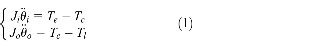
The driving part and driven part achieve synchronous response behavior in the stick state. Assuming the displacement as θio, the equations of motion for the model are given in the following.
The dynamic equation of synchronizing process is

where Te is the torque of engine transferred to the clutch driving part, Tl is the load torque, and Tc represents the torque transmitted by the clutch.
Modeling of transmitted torque of clutch function during engagement
Each end of the spring fits into a counterbore in the housing. The energizing coils, equation reference goes here three coils at each end of the spring, are larger in outside diameter than the remainder of the spring, and they fit their respective counterbores with a small amount of interference. Besides the energizing coils, there is a diametral clearance (ΔD) between the spring outside diameter and drum inside diameter when the clutch is unloaded. The clearance gradually decreases to zero as the spring begins to twist. The energizing coils have the smallest cross-section to reduce the amount of torque needed for energization. During engagement, the torque applied to the spring through the friction on the end coils causes the spring to enlarge progressively until the entire spring fits tightly in the bores of the housings. The spring then acts as a common pilot in the bores of the input and output housings, thus providing the reaction to the shear load between the housings.
There are two phases during clutch be engaging, spring expanding and spring locking. Without be loaded, the torque spring makes no attachment with the drum. The engine drives the input element to rotate, making relative replacement between input and output. The spring expands radially when input housing rotates faster than the output. Due to the friction with holes’ surface, the spring expands and attaches with drum gradually from the energizing coils to the central coil.
According to different work conditions and phases during engagement, the clutch torque can be defined as a stepwise function
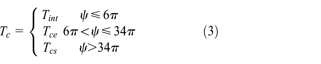
where Tint is the pre-load torque which counts on the interference fit between energizing coils and drum, Tce is the torque transmitted by the clutch during clutch engaging, and Tcs represents the torque transmitted by the clutch when clutch begins to lock

The arc length of spring coil does not change during expansion; equation (13) can be obtained as follows


where φ represents the torsional angle between input and output housings. θf and θe represent the radian of spring coil in the free state and the expanded state, respectively. Combining equations (4) and (5), the relationship between φ and θf can be expressed by equation (6). It can be concluded that the ratio of the torsional angle of the clutch to the radian of spring coil in the free state is constant because of the constant clearance.
As the spring twists, the spring unwinds from the shaft and wraps into the drum. Ψ represents the spiral polar angle of spring coil that is connected to the inside surface of drum. Due to invariable diametral clearance (ΔD), the torsion angle for coil expanding is constant. Therefore, the relationship between relative angular replacement φ = θi – θo and ψ is given as follows:

where ϕ is the relative angle when spring expands finished and N is the total number of turns of the spring; therefore, 2Nπ is total radians of the spring coil.
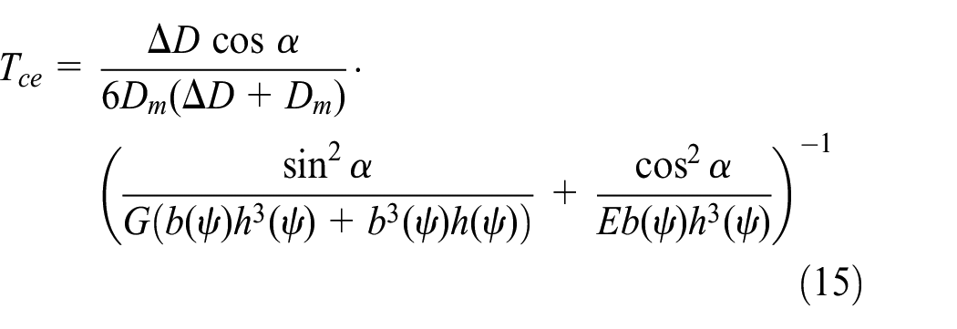
According to the theory of material mechanics and basic principle of spiral spring, the function of torsion angle of spring is given as follows

where Tc is the torque which clutch suffered and transmitted; θL represents the angle of the spring coil that has expanded; Dm is the mean diameter of spring; α is the helical angle of spring; E and G are the elasticity modulus of spring material and the modulus of rigidity, respectively (Figure 5).

Key structure parameter of torsional spring shown in the section diagram.
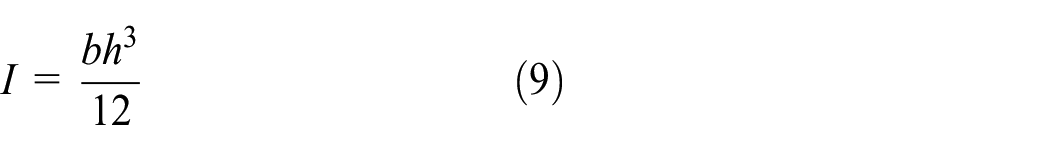
The moment of inertia of rectangular cross-section is
The polar moment of inertia of rectangular cross-section is

where b is the spring coil width and h is the spring radial height. Because the coil section varies, the width and radial height of coil are not constant. The law of variation for parameters b (mm) and h (mm) is given as follows
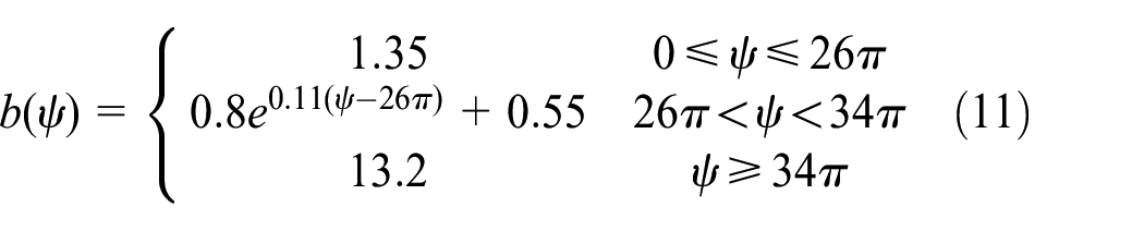
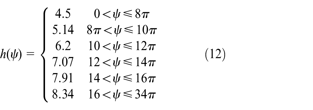
Since the width of the coil is variable, the changing helix angle α cannot be ignored. The t is pitch of spring and δ is the gap between spring coils


Equation (12) expresses the relationship between the torque and resulting angular deflection when spring expands
When spring coils contact with the drum, the spring fully expands and then the engagement of the clutch enters the spring locking phase. Because of speed difference between the input and output of clutch, clutch has a slight slip until be locked. In the spring locking phase, the torque which clutch transmitted can be defined as

where kc is the stiffness of wrap–spring clutch after spring contacts with drum and Tcemax represents the torque transmitted by the clutch when spring fully expands.
Numerical simulations
Numerical simulations have been programmed in MATLAB, which has used the fourth-order Runge–Kutta numerical integration to solve the differential equations. The torque applied to both ends of the clutch (Te, Tl) remains equal and constant except in the overrunning state. Considering different states and changing torque of clutch in engagement process, the numerical simulation is piecewise. Table 1 shows the system parameters which include the spring key geometric parameters and the rotational inertia of input shaft and output shaft.
Model parameters.

As stated in the “Dynamic modeling” section, the clutch has different equations of motion for each state. Two event functions in program have been established to switch motion equations in different states. The integral stops at the point where the event functions have been detected. Then the integral enters the next state, and the final result of the previous state will be the initial value of this state. In this program, the event function is decided by the value and direction of relative angular velocity between driving part and driven part. The integral will stop when the speed difference is zero and its direction is increasing or decreasing, respectively

where Δωc represents the relative angular velocity between driving part and driven part of clutch. The direction in which the clutch can transmit torque is set to the positive relative direction

The integral stops when event functions E1(Δωc) and E2(Δωc) equal to 1. The flow chart of solution program of whole process is shown in Figure 6, which contains the motion equation of three states.

Flow chart of solution program of engagement process.
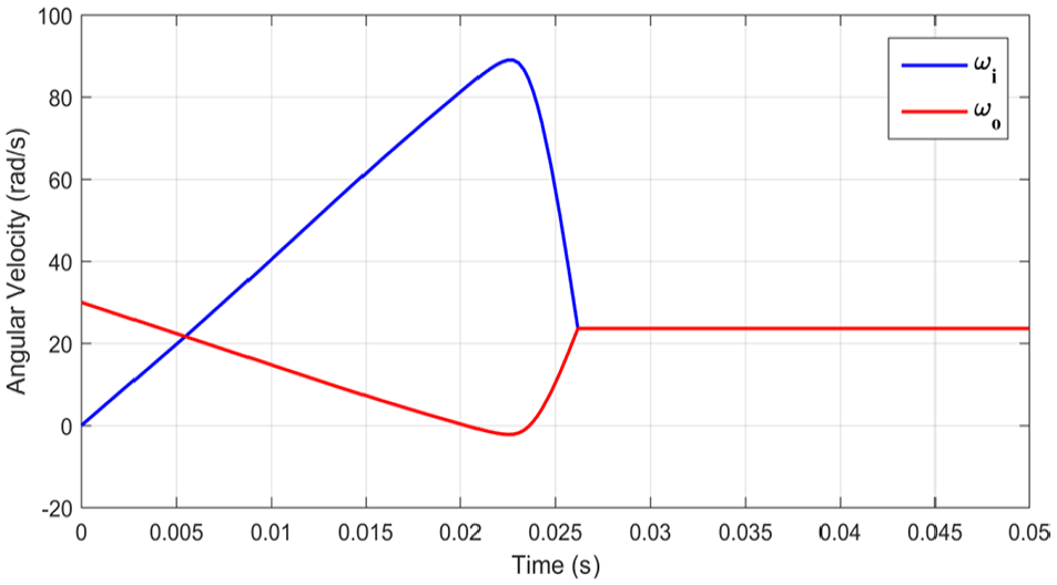
This section analyzes the transient engagement process of clutch under two conditions, engagement in starting at rest and reengagement after overrunning. The engagement characteristics of the clutch are described by time-domain diagrams of rotation speed and angle in this article. Figures 7–9 depict the start-up process of both ends of the clutch at rest. Figures 7–9 represent the angular velocity characteristics of the input and output shafts, the relative angular displacement characteristics, and the transfer torque with relative torsional angular displacement during the start-up process, respectively. Figures 10–12 depict the reengagement process of one-way clutch after overrunning. Figures 10–12 represent the angular velocity characteristics of the input and output shafts, the relative torsional angular displacement characteristics, and the transfer torque with relative angular displacement during the reengagement process, respectively.

Input shaft and output shaft angular velocity characteristics during clutch start-up.

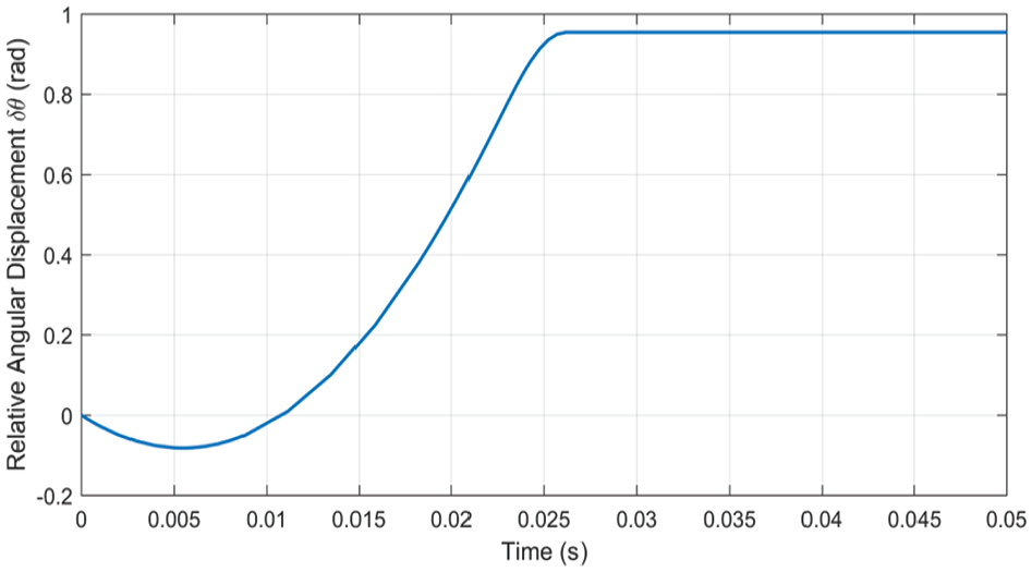
Torsion angle characteristics during clutch start-up.

Transfer torque characteristics during clutch start-up: (a) whole process and (b) enlarged view (0–20 N m).
Input shaft and output shaft angular velocity characteristics during reengagement.
Torsion angle characteristics of clutch reengagement.

Transfer torque characteristics during clutch reengagement: (a) whole process and (b) enlarged view (0–20 N m).
Parameters effect
This section discusses the effect of clutch parameters on the engagement process. Three key dimensions of the clutch, coil width b, diametral clearance ΔD, and number of coil turns N, are selected to study the effect of clutch structure parameters on the transient process of engagement. The relevant parameters of energizing coils are not considered because they only affect clutch initial torque Tint.
Figures 13–15 show that the increase of coil width makes the clutch torque Tc increase and the increasing rate of Tc increases, thus changing the angular acceleration of the input and the output, reducing the relative angle displacement, and shortening the time required for the engagement.

Compare the angular speed characteristics of different coil widths.

Compare torsion angle characteristics of different coil widths.

Compare transfer torque characteristics of different coil widths: (a) whole process and (b) enlarged view (0–20 N m).
Figures 16–18 show that the there is an increase in the diametral clearance Tc, but there is no change in the increasing rate of Tc, thus not affecting the angular acceleration of the input and output. The engagement time increases and relative angle displacement during engagement increases.

Compare the angular speed characteristics of different diametral clearances.
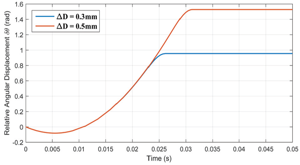
Compare torsion angle characteristics of different diametral clearances.

Compare transfer torque characteristics of different diametral clearances: (a) whole process and (b) enlarged view (0–20 N m).
Figures 19–21 show that reducing the number of coil turns makes Tc start to increase rapidly earlier, so that the engagement can be completed earlier, and the relative angular displacement in the engagement process can also be reduced.

Compare the angular speed characteristics of coils with different numbers.
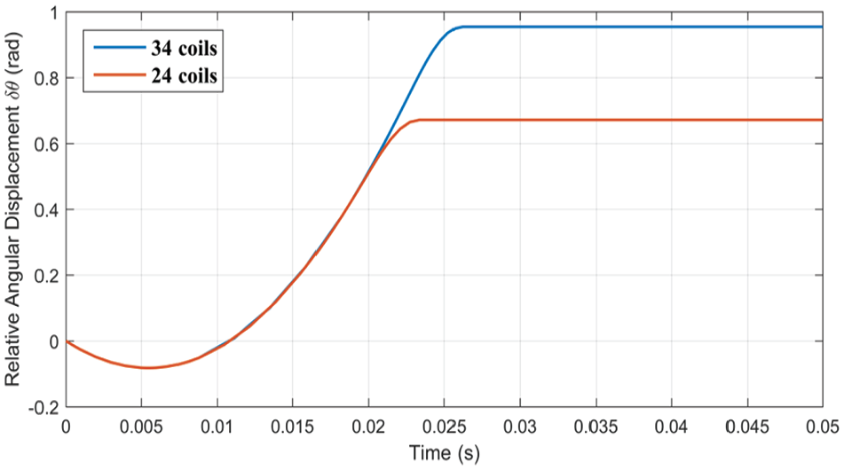
Compare torsion angle characteristics of coils with different numbers.
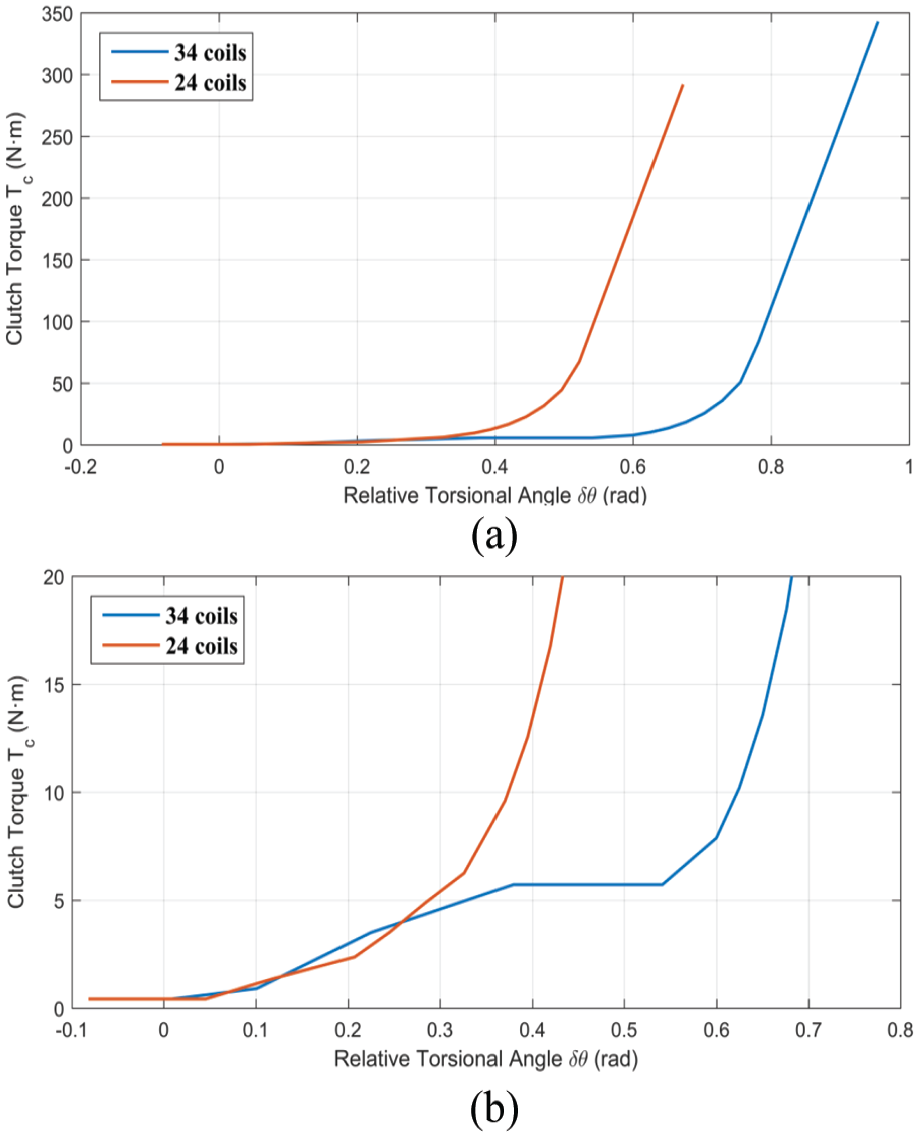
Compare transfer torque characteristics of coils with different numbers: (a) whole process and (b) enlarged view (0–20 N m).
Experiment and results
An experiment rig is built to test the dynamic characteristics of the clutch, which consists of driveline, measurement system, and power and its control system. As shown in Figure 22, the driveline mainly includes input shaft, input angular displacement transducer, wrap–spring clutch, output shaft, and output angular displacement transducer. The input and output ends of the driveline are connected with the speed motor and the load motor, respectively. In order to verify the dynamic model and clutch torque model established in this article, a dynamic experiment with spring clutch is conducted. The rotational speed of the input or output shaft is calculated by the frequency of the pulse signal of the angular displacement encoder. The data acquisition program is used to convert the pulse signal generated by the angular displacement transducer into the values of angular displacement and rotational speed, and its flow chart is shown in Figure 23. Figure 24 shows the angular velocity of the input and output ends in the process of clutch engagement in the experiment. Figure 25 represents the experiment result of torsion angle of clutch during engagement.

Picture of the driveline in the experiment rig.

Flow chart of the data acquisition program.

Experimental results of angular velocity characteristics in clutch engagement process.

Comparison of experimental results with numerical results of torsion angle in clutch engagement process.
The experimental procedure is given as follows: turn on the data acquisition system and then start the motor at the output end. After keeping a certain speed (over 350 r/min), start the motor at the input end. When the speed of the input exceeds the speed of the output, and the input and output move together, the clutch is engaged. The final rotational speed is maintained at higher revolutions per minute than before.
Conclusion
In this article, the dynamic equation describing the engagement process of one-way clutch with variable cross-section torsional spring is established; torque transmitted by the clutch during engagement is modeled by a multi-parameter function. The engagement process of clutch is described by the characteristics of angular velocity, torsion angle, and transfer torque. Through the analysis of numerical simulation and experimental results, the following conclusions are drawn:
According to Figures 24 and 25, simulation results are basically consistent with experimental results. It can conclude that the theoretical model established in this article is effective. The difference in Figure 25 may be due to manufacturing or installation errors of the clutch. Some of the fluctuations in the experimental results are mainly caused by motor speed fluctuation and driveline vibration.
It can be concluded from both theoretical calculation and experimental results that the engagement process of the spring clutch is relatively transitory and smooth.
In order to study the effect of the parameters on the engagement characteristics of the clutch, three key geometrical parameters of the clutch were separately analyzed while other parameters were unchanged. Increasing the width of the coil will change the function of the coil width. According to Figures 13 and 14, the change of the coil width equation is proved to affect the engagement characteristics: increasing the coil width would shorten the engagement time of the clutch and sharpen the slope of the velocity curve when engaging. According to Figures 16 and 17, increasing the diametral clearance will shift the engagement curve to the right, indicating that increasing the clearance will delay the completion of the engagement but will not change the slope of the curve. The total length of the spring coil is determined by the winding number since the diameter is constant. Reducing the number of coils would shorten the total length of the coils. According to Figure 19, a wrap–spring clutch with fewer coils will engage more quickly. And shortening the constant section ring of the spring would also make the spring clutch torque smoother.
Footnotes
Handling Editor: Hui Ma
Declaration of conflicting interests
The author(s) declared no potential conflicts of interest with respect to the research, authorship, and/or publication of this article.
Funding
The author(s) disclosed receipt of the following financial support for the research, authorship, and/or publication of this article: This study was supported by the National Natural Science Foundation of China (NSFC) through grant nos 51575533 and 51805555 and the Applied Basic Research Key Program of Hunan Province (2015JC3007).