
Abstract
In the shift process of large-order automatic transmission, jitter phenomenon is common in clutch engagement process, which greatly affects the ride comfort of the vehicle. In this article, the jitter dynamic model of clutch engagement process was established with lumped mass method and virtual displacement principle. Specific to clutch engagement stage, the optimal control of the coordination between driving motor and wet clutch was studied. In accordance with the jitter dynamic model, the state–space equation with controlling variables of motor torque and clutch friction torque was established. In this optimization problem, the torsion angle, torsion angular velocity, and shift jerk are selected as optimization targets. Utilizing the linear quadratic optimal control theory, the optimal trajectory of motor torque and clutch friction torque was obtained. Aiming at the dynamic responses in clutch engagement process, the optimal control in different conditions of weight coefficients, initial torsion angles, and resistance torques was studied. Results showed that the optimal control strategy could obviously reduce the jitter; in addition, the weight coefficient should be determined according to actual situation reasonably.
Introduction
The integration of motor and gearbox is becoming a trend of electric driving system for electric vehicles. Two-gear planetary transmission can well match with high-speed motor, which has good application prospect and practical value because of the advantages of large speed ratio and transmission torque, high power density and efficiency, and flexible shift control method. In clutch engagement process, the driving disk and driven disk of the clutch achieve synchronization under the action of friction torque. However, the jitter phenomenon appears frequently as a disturbance in shift process because of the large difference in shift speed, which greatly affects the ride comfort of transmission system, worsens the wear of clutch disk, and shortens the life of transmission part.1–4 At present, the solutions mainly concentrate on anti-jitter ability by physical means, which cannot behave well all the time. Active control is the key of jitter suppression in shift process.5,6 The coordination control of clutch and driving motor is a method easily to be realized, which can well reduce the jitter in clutch engagement process and greatly improve shift quality. 7
In the researches of clutch control, Song and Sun 8 designed a sliding mode controller based on clutch pressure to guarantee the precision and robust of the control system; H Hwang et al. 9 reduced the shift jerk caused by the fluctuation of clutch torque through motor torque compensation; A Haj-Fraj and F Pfeiffer 10 realized the optimal control in clutch engagement process with dynamic programming method by considering the shift process as decision by stages; L Glielmo and F Vasca 11 studied on the engagement process of dry clutch with linear quadratic theory, which behaved well on the improvement of shift quality. On the coordination control of transmission system, K-J Yang 12 designed the shift controller for inertial phase based on optimal control method, in which the engine torque and clutch pressure are regarded as control variables. C Xiusheng et al. 13 and Y Liu et al. 14 studied on the coordination control strategy of automatic transmission equipped with dual clutch. High precision and fast response performances are critical for actuators in clutch control system. F Meng et al.15,16 studied on the modeling process and pressure control method of the clutch actuator for automatic transmission systems, which was significant for the development of control strategy of clutch control.
In this article, specific to clutch engagement process, the optimal control of the coordination between driving motor and clutch was studied. The torsion angle, torsion angular velocity, and shift jerk are selected as optimizing targets. Utilizing the linear quadratic optimal control theory, the optimal trajectories of motor torque and clutch friction torque were obtained. By active control, the jitter in shift process was reduced.
Structure and working principle of two-gear transmission
The powertrain with a two-gear transmission and combined clutch is considered here, as schematically shown in Figure 1. The transmission system consists of a driving motor and two-gear planetary transmission. In the transmission, power is input by sun gear and output by planet carrier. The clutch C and brake B are structurally connected to make up a combined clutch, which is controlled by a hydraulic system, and the oil pressure could act on cylinder piston directly to complete shift action.
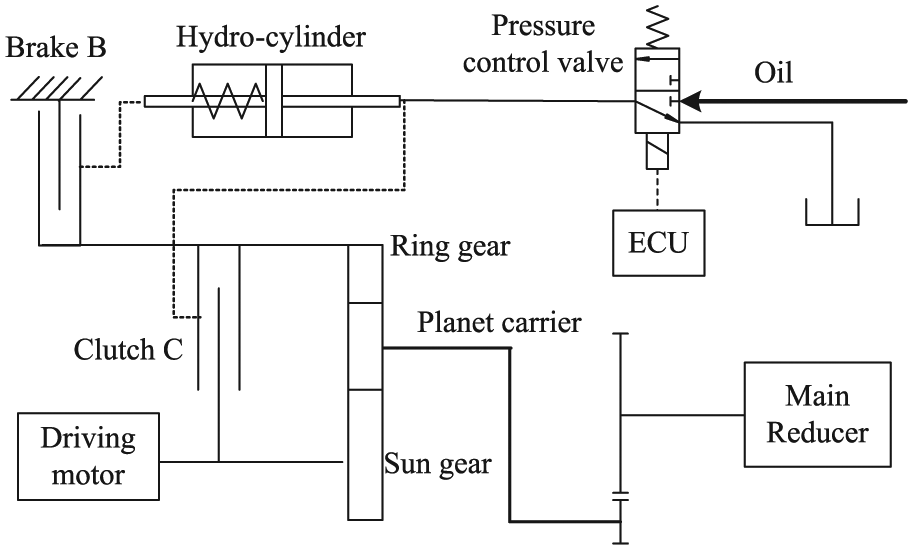
Schematic diagram of two-gear transmission.
To realize downshift process, the electric control unit (ECU) will enable oil charging circuit, and the increasing oil pressure will first push the piston to make clutch C disengaged; after a short free phase, along with the continuous movement of the piston, the friction disks of brake B are pressed tightly by the piston and then brake B is engaged, and downshift process is completed. On first gear, the transmission ratio is given as i1 = 1 + k, where k is the ratio of the teeth number of ring gear to that of sun gear. To realize upshift process, ECU will enable oil discharging circuit; under the effect of return spring and gradually decreasing oil pressure, brake B is disengaged; after a short free phase, the piston is pushed to press the friction disk of clutch C tightly to engage the clutch, and upshift process is completed. At second gear, the transmission ratio is given as i2 = 1.
The jitter appears in clutch engagement phase obviously; thus, the jitter suppression in upshift process is studied in this article, and some main parameters of the targeted vehicle are listed in Table 1.
Relevant parameters in vehicle shift process.

Analysis model of jitter dynamics in clutch engagement phase
To establish the jitter dynamic model of two-gear transmission, all the components of powertrain are assumed as concentrated mass; the viscosity damping of transmission shaft, bearings, and gear mesh is ignored. All the simplifications above will not produce too much influence on dynamic analysis of shift process. 17 The planetary transmission is modeled as schematically shown in Figure 2, where T represents the torque, J the moment of inertia, θ the rotation angular, ka the torsional stiffness, and ca the damping, and all subscripts of relevant parameters are shown in Figure 2.

Driveline model of the combined clutch and two-gear transmission.
In the engagement process of clutch, there are


By virtual displacement principle and D’Alembert’s principle


where

The torque transferred by combined clutch is given by equation (7). Upshift process includes three phases: brake B disengagement phase, free phase, and clutch C engagement phase. In brake disengagement phase, Tcl = 0 and Tbr ≠ 0; in free phase, Tcl = Tbr = 0; and in clutch engagement phase, Tcl ≠ 0 and Tbr = 0. So, the torque is transferred by combined clutch in the first and third phases only

where µ is the friction coefficient of friction disk and is assumed as a constant for simplification; N is the number of friction pairs; and R1 and R2 are, respectively, the inner and outer radii of friction disk. According to equation (7), there is a direct corresponding relationship between clutch torque and oil pressure.
Construction of performance function
In clutch engagement process, the speed difference between driving disk and driven disk of clutch will cause sliding friction; meanwhile, the rotation speed of motor, clutch, and output shaft of transmission will fluctuate violently. The fluctuations may cause larger shift jerk and dynamic load factor so that the life of transmission part might even be shortened.18,19 Aiming at the jitter suppression in clutch engagement process, the torsion angle θa = θm − θc1 and torsion angular velocity
Shift jerk j evaluates the comfort of transmission in shift process, which is defined as the changing rate of vehicle longitudinal acceleration

where rw is the radius of wheel.
In clutch engagement process, it is further expressed as

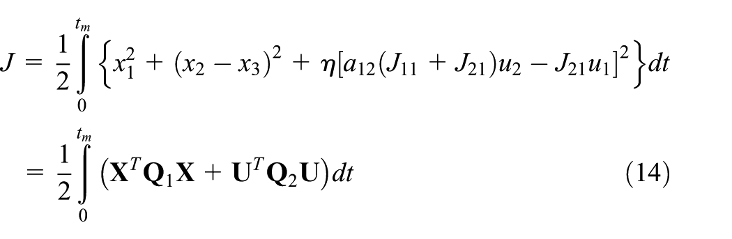
Taking torsion angle, torsion angular velocity, and shift jerk as comprehensive control targets, the performance function is constructed as

where η is the weight coefficient of shift jerk and 0 < η < 1. The larger the weight coefficient, the greater portion the shift jerk is considered in the evaluation criterion.
Solving process of optimal control trajectory
Considering about the shift jerk expressed in equation (8), the state variables are considered as follows

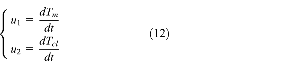
The torque of driving motor and clutch are considered as the control objects in this optimization problem. Define the control variables as
Substituting equations (10) and (11) into equations (2) and (4)–(6), the state–space equation is expressed in the following form

where

The matrix

At the end of clutch engagement process, the clutch is engaged completely, and the ring gear and sun gear of planetary transmission achieve synchronization. Thus, the terminal constraint is

where
Linear quadratic optimal control
The control law worked out by linear quadratic optimal control is the linear function of state variables, which endows it with significance in engineering. In the shift control, disturbance matrix is out of consideration generally. However, it exists in this article for accurate control model further.
The linear time-varying system can be written in the following state–space model

where V is the disturbance matrix. We look for a control which minimizes the performance index

The Hamiltonian dynamic equation governing the clutch engagement can be constructed and presented in the following form

where
According to the maximum principle, equation (23) can be acquired

equally

Using the Hamiltonian approach and the adjoint equation, this corresponds to solve the following set of differential equations

with the set of conditions


where t0 is initial time, tf is the terminal time, v is the unknown constant, and N is the terminal constraint.
Considering the effect of the perturbation matrix and the terminal constraint, defining


where
By substituting equations (24) and (25) into equation (20), after simple algebraic manipulations, one obtains the following three matrix differential equations


These differential equations can be solved backward in time from the above terminal conditions. Now, by differentiating equation (25), we have

and using equation (20)

that holds for any X(t) and v. Therefore


which determine K(t), L(t), and r(t). From equation (21), since v is a constant, one obtains

Finally, the optimal control variables
Analysis of optimal control effect for clutch engagement
Assume that the initial torsion angle θa = 0.01 rad, the initial torsion angular velocity ωa = 1.5 rad/s, the initial speed of motor ωm = 225 rad/s, the resistance torque Tf = 731 N m, and the weight coefficient η = 0.1. The comparisons between that without control strategy and with control strategy are shown in Figures 3–6.

Comparison of the transmission system speed: (a) without the control strategy and (b) with the control strategy.

Effects of active control for jitter suppression.

Comparison of the effects between different weight coefficients.
Comparison of the effects between different resistance torques.
According to the comparison between Figure 3(a) and (b), the jitters of system speed are significant in the case of without active control; however, the concussions converge after the application of active control, which shows the good effect of active control. As shown in Figure 4, without active control, the torsion angle and torsion angular velocity sustain concussion and even keep a divergence tendency. After the application of control strategy, the concussion weakens significantly, and the speed of motor, clutch, and ring gear is converged rapidly; the speed of output shaft turns mild at the end of clutch engagement. As for the control objects, motor torque and clutch torque increase in different degrees. As a comparison, the shift jerks are, respectively, 5.7 and 8 m/s3; the friction works are, respectively, 3997 and 4862 J. Consequently, the shift jerk and friction work are all increased in a permission scope after the application of control strategy. In conclusion, the active control can well reduce the jitter in clutch engagement process.
Analysis of optimal control effect on different weight coefficients
Set the initial torsion angle θa = 0.01 rad, initial torsion angular velocity ωa = 1.5 rad/s, initial motor speed ωm = 225 rad/s, and resistance torque Tf = 731 N m. The comparisons between the active controls under different weight coefficients η = 0.1 and η = 0.01 are shown in Figure 5.
As shown in Figure 6, with the decrease in weight coefficient, the concussion of torsion angle and torsion angular velocity attenuate faster, and the torsion angular velocity reduces to zero rapidly; the concussion amplitude of motor speed, clutch speed, and ring gear speed is reduced in different degrees.
However, with the decrease in weight coefficient, the jitter appears in motor torque and clutch torque in different degrees, which shows that jiggling torque of motor and clutch can reduce the jitter and accelerate the convergence. The shift jerk and the friction work are increased, and this is because the shift jerk is considered in a smaller portion in the evaluation criterion for the smaller weight coefficient.
Through the analysis, we can conclude that the reduction in weight coefficient can accelerate the jitter decreasing, but it may increase the jitter of motor torque and clutch torque, which shows that we should choose a suitable weight coefficient according to the actual situation.
Analysis of optimal control effect on different resistance torques
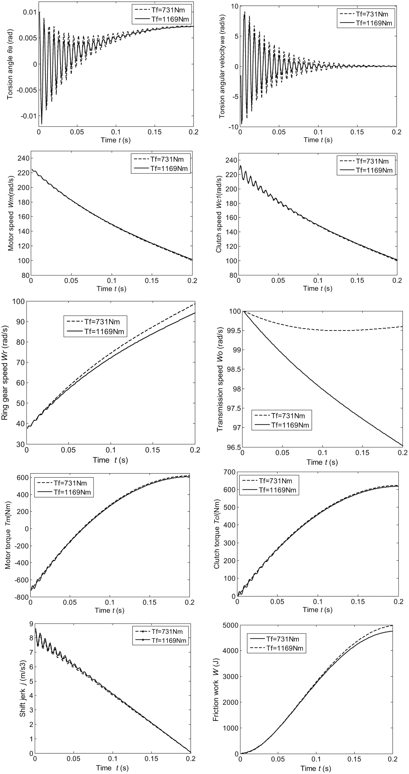
Set the initial torsion angle θa = 0.01 rad, initial torsion angular velocity ωa = 1.5 rad/s, initial motor speed ωm = 225 rad/s, and weight coefficient η = 0.1. The comparisons between the active controls under different resistance torques Tf = 731 N m and Tf = 1169 N m are shown in Figure 6.
As shown in Figure 6, with the increase in resistance torque, the concussion of torsion angle and torsion angular velocity attenuate slower; the concussion range of motor speed and clutch speed increased in small amplitude and the output speed of transmission reduced. With the increase in resistance torque, the jitter appears in motor torque and clutch torque, and shift jerk and friction work increase in some degrees.
Through the previous analysis, we can conclude that with the condition of different resistance torques, the control strategy is verified. Although the jitter increases under larger resistance torque, it is reduced to ideal effect finally.
Analysis of optimal control effect on different initial torsion angles
Set the initial torsion angular velocity ωa = 1.5 rad/s, initial motor speed ωm = 225 rad/s, weight coefficient η = 0.1, and resistance torque Tf = 731 N m. The comparisons between the active controls under different initial torsion angles θa = 0.01 rad and θa = 0.03 rad are shown in Figure 7.

Comparison of the effects between different initial torsion angles.
As shown in Figure 7, with the increase in initial torsion angle, the convergence rate of torsion angle and torsion angular velocity reduced significantly, and the concussion range of motor speed and clutch speed increased greatly. With the increase in initial torsion angle, the jitter appears in motor torque and clutch torque; shift jerk is increased in some degrees, and the friction work is largely reduced.
Through the analysis, we can conclude that a small increase in initial torsion angle will lead to a large increase in jitter of clutch; however, the application of control strategy could still be effective on the suppression of jitter.
Conclusion
The optimal control strategy of jitter suppression in clutch engagement process of two-gear planetary transmission is studied in this article. The dynamic model of combined clutch in engagement process is established. According to linear quadratic optimal control theory, taking the torsion angle, torsion angular velocity, and shift jerk as control targets and the torque of motor and clutch as control objects, the state–space model of clutch engagement process is built. The control trajectory was obtained, which was verified effectively in the jitter suppression of shift process.
Taking the dynamic characteristics in clutch engagement as research object, the control effects of different weight coefficients, resistance torques, and initial torsion angles are verified. Results showed that the reduction in weight coefficient will accelerate the convergence of jitter, the increase in resistance torque will aggravate the jitter and increase the shift jerk and friction work, and a small increase in initial torsion angle will lead to a large increase in jitter of clutch. The application of control strategy is effective on the suppression of jitter.
Footnotes
Acknowledgements
Author Yizheng Wang is now affiliated with Beijing Electric Vehicle Co., Ltd. Beijing, China.
Academic Editor: Hamid Reza Shaker
Declaration of conflicting interests
The author(s) declared no potential conflicts of interest with respect to the research, authorship, and/or publication of this article.
Funding
The author(s) disclosed receipt of the following financial support for the research, authorship, and/or publication of this article: This work was supported by National Natural Science Foundation of China (no. 51475042).