
Abstract
In order to realize the automatic strengthening for turbine blades, a path planning method for robotic ultrasonic surface strengthening is proposed. A constitutive model of nonlinear isotropic strengthening–kinematic hardening is analyzed to establish the dynamic response model of ultrasonic surface strengthening on the turbine blade. According to the dynamic response model, the impact depth of the ultrasonic working head was obtained. Then, a path planning method of robotic ultrasonic surface strengthening for turbine blades is proposed on the basis of impact depth of working head, and it can improve both the uniformity of path distribution and contour accuracy. It not only ensures the processing accuracy but also meets the uniformity requirement of coverage. This path planning method provides a new surface strengthening technology for turbine blades.
Keywords
Introduction
The surface quality of parts significantly affects their wear resistance, corrosion resistance, compatibility, and sealing performance. Ultrasonic surface strengthening technology has a very strong strengthening ability for fine finishing surface, which improves the hardness and wear resistance of the processed surface, reduces the surface roughness, and has low processing cost and significantly improves the production efficiency. 1 At present, ultrasonic surface strengthening technology is widely used in strengthening regular surfaces (such as plane, cylindrical surface, and spherical surface), and surface strengthening of regular surface is mainly carried out by integrating an ultrasonic surface strengthening system on a universal machine tool. However, for free-form surface parts (such as turbine blades, propeller blades, and mold cavities), the path of strengthening operation is complex, so the application of ultrasonic surface strengthening technology for such parts is less.
As the structure and performance of industrial robots fully reflect the advantages of automation equipment, especially intelligence, adaptability, accuracy of machine operation, and adaptability to operations in various environments, industrial robot technology is increasingly applied to the processing of curved surfaces. In view of this, this article proposes to use industrial robots to carry out ultrasonic strengthening on free-form surfaces, trying to solve the technical problems existing at present. When the ultrasonic vibration parameters are fixed, the strengthening path and trajectory planning directly determine the efficiency and the final surface quality of ultrasonic surface strengthening. This represents one of the key technical problems to realize high-quality surface and strengthening finishing processing. Currently, the path generation methods of processing freedom hook face are mainly include parallel section method, 2 isoperimetric line method, 3 equal chord error method,4,5 equal residual height method, isometric bias method, polyhedral method, feature Extraction method, and Z-map method.6–8 After the path generation method is determined, the row spacing and path points of the ultrasonic surface strengthening on each path and their corresponding tool poses of ultrasonic surface strengthening need to be determined according to the process requirements. The choice of row spacing determines the final quantity of paths. If the row spacing is large, then the quantity of paths is small, which may result in a low percentage of surface coverage, thus the surface of the workpiece may not be completely strengthening finishing. If the row spacing is small, the quantity of paths will be much larger, which makes the processing time longer—affecting the processing efficiency, and it may even cause local over-machining with the generation of micro-cracks.
The choice of the path point of ultrasonic surface enhancement may affect the contour accuracy of the surface strengthening track. If the point is too sparse, then there is a bad lamination between the strengthening track and contour, resulting in a low accuracy the contour, which is inclined to cause a rigid impact on the ultrasonic surface strengthening actuator or the robot system, finally obtaining a bad quality of surface strengthening finishing; an over-dense path points may lead to a good contour accuracy. However, it will seriously slow down the processing efficiency. The pose in the working point of the ultrasonic surface strengthening tool affects the contact force between the ultrasonic surface strengthening tool and the workpiece, which in turn affects the contact area and elastoplastic deformation quantity in the process of vibration strengthening. Too small or too large contact force will severely affect the plastic deformation quantity, further results in uneven residual compressive stress layer as well as uneven surface roughness of the workpiece.
Reasonable path planning of the robotic ultrasonic surface strengthening for the turbine blade requires a dynamic response model of ultrasonic surface strengthening on turbine blade, in order to improve both the uniformity of path distribution and contour accuracy. It not only ensures the processing accuracy but also meets the uniformity requirement of coverage.
Mechanical model of ultrasonic surface strengthening for turbine blades
Constitutive model of nonlinear isotropic strengthening–kinematic hardening
During process of ultrasonic rolling, the working head acts on the surface of the material with ultrasonic mechanical vibration, resulting in severe elastoplastic deformation in the surface layer of the material with significant strain hardening and strain rate hardening. Obviously, the selected constitutive model should take into account the effects of strain hardening and strain rate hardening. The constitutive model of nonlinear isotropic strengthening–kinematic hardening is a combination of the isotropic strengthening constitutive relation and the kinematic hardening constitutive relation. These relations not only contain the effects of temperature, strain, and strain rate but also characterize the material under cyclic loading. At the same time, this model contains the Bauschinger effect, which reflects the anisotropic properties of the material and is very close to the actual situation of ultrasonic surface strengthening. At the same time, it is also a material constitutive relationship commonly used in numerical simulation of surface treatment such as shot peening. For example, Klemenz et al. 9 harnessed this model to evaluate the surface properties of the material after shot peening.
The nonlinear isotropic strengthening–kinematic hardening constitutive model is on the basis of the kinematic hardening constitutive model and takes the isotropic strengthening effect of the material into consideration. Generally, the basic kinematic hardening model adopts the modified Chaboche model, and the factors that affect deformation will be taken into account, such as deformation history, strain rate, and temperature. The complete equation of modified nonlinear isotropic strengthening–kinematic hardening constitutive is described below.
The strain tensor

where E and v, respectively, are the elastic modulus and Poisson’s ratio; the stress tensor is σ; and the second-order unit tensor is I.
In the stage of plastic deformation, the yield of the voxel obeys the von Mises condition, and the mathematical expression of the yield surface is equation (2) 11

where
In the modified Chaboche model, the back stress consisting of several components is expressed as equation (3)

where

where
The parameters
The plastic strain


where

The equivalent stress

where
The material will undertake effect induced by high-speed loads during the ultrasonic surface rolling process, where both the instantaneous stress and yield limit will increase with the increase in the strain rate. At the same time, the rising temperature due to the strong load will reduce the instant stress and yield limit. Relevant studies have shown that there is a rising temperature phenomenon caused by high-speed impact, which is usually within tens of degrees Celsius in the surface nanofabrication such as ultrasonic peening, so the effect of temperature on the mechanical behavior of the material can be ignored the constitutive model in this article. However, the present mechanical properties induced by the strain rate cannot be negligible, so the strain rate parameters are introduced in the isotropic strengthening part of the nonlinear isotropic strengthening–kinematic hardening constitutive model, shown as equation (9)

The material of turbine blade is TC4 titanium alloy. The undetermined material parameters in equation (8) can be obtained by the uniaxial tension curve and the tension–pressure symmetrical cyclic stress–strain curve, 15 so that the material parameters in the nonlinear isotropic strengthening–kinematic hardening constitutive model can be solved. The calculated parameters of modified nonlinear isotropic strengthening–kinematic hardening constitutive model are shown in Table 1.
Parameters of nonlinear isotropic strengthening–kinematic hardening constitutive model.

Dynamic response of ultrasonic surface strengthening
The ultrasonic power supply has an automatic frequency tracking function. The vibration frequency of the working head will change with actual working conditions (such as change of the material nature being processed and processing parameters) during the machining process. Otherwise, the amplitude is only the ideal displacement of the working head, which is not full enough to reflect the actual impact of the working head on the material. Therefore, the dynamic monitoring system of the ultrasonic surface rolling is employed to obtain the actual impact force of the material surface during the processing.
According to Cao et al.’s 16 experiment on ultrasonic surface strengthening of TC4 titanium alloy, it can be seen that the surface properties of TC4 workpiece can be significantly strengthened at static pressure of 25 N and amplitude of 30 μm. Therefore, the dynamic testing of the impact process of the working head is carried out with this parameter. The SDT1-028K piezoelectric thin film and VK10x precision charge amplifier are applied for measurement of dynamic impact force in this test. This dynamic detection system is based on the principle of piezoelectric effect. When the vibration of the working head acts on the surface of the material, the material will be subjected to the corresponding force. The piezoelectric thin film senses and converts the force into the charge with same proportion. Then, the charge is converted into a readily readable voltage or current information. Finally, it is reflected by the display device. Through conversion, the real change of the impact force can be obtained. The dynamic impact force amplitude is 8.3 N and the frequency is 21.3 kHz under static pressure of 25 N.
Simulation analysis for the motion state of the working head with ultrasonic surface strengthening
As illustrated in Figure 1, the finite element model of ultrasound surface strengthening is established, where the diameter of working head is 5 mm and the size of workpiece is 40 mm × 40 mm × 10 mm.

The finite element model of ultrasound surface strengthening: (a) holistic diagram and (b) grids at contact position.
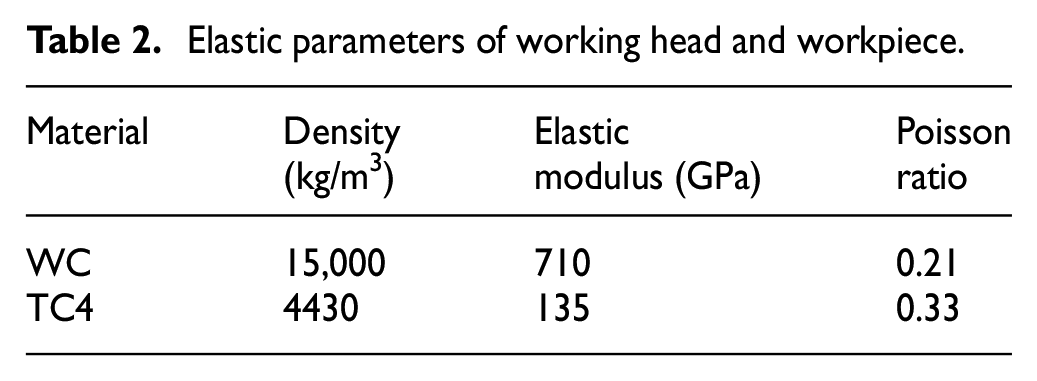
The material of working head is cemented carbide (WC), its stiffness is much larger than the stiffness TC4 titanium alloy, so only the isotropic linear elastic parameters is given to the working head. The elastic parameters of working head and workpiece are shown in Table 2, and the parameters of modified isotropic enhancement–synchronization hardening constitutive model in Table 1 are used here as plastic parameters.
Elastic parameters of working head and workpiece.
It is known that the initial loading conditions are static pressure and the output end amplitude of the working head, but it is contradictory to simultaneously apply the force and displacement in 1-degree of freedom (DOF). So here, the dynamic impact force measured by the dynamic detection system is used to replace the amplitude as the initial input condition. Constant static pressure and dynamic impact force are both concentrated forces which should be applied to the reference point of the working head. Since the working head not only transmits the force but also has rolling contact with the surface of the material, the position of reference point is defined at the center of the sphere. The dynamic impact force generated by the mechanical vibration of ultrasonic frequency varies as the sinusoidal function, so the impact force with periodic variation is loaded according to the sinusoidal function.
Figure 2 illustrates the displacement of the working head within 2 ms. It can be seen that the working head moves the largest distance in the first impact, where the static pressure plays a big role in this impact. Since the effect of static pressure always exists, the working head will not return to the initial position when rebounding back, so the value of the displacement is always negative. The fluctuation phenomena of the working head’s displacement indicate that the material is in an alternating state of elastic deformation and springback. The maximum impact depth of the TC4 titanium alloy with ultrasound surface strengthening is 0.184 mm.

Displacement variation of working head.
Path planning of robotic ultrasonic surface strengthening for turbine blades
The acquisition of contact point for the working head in processing direction
There is no way to appoint all the points on the geometric track when performing processing of robotic ultrasonic surface strengthening, and only a part of the points can be extracted as the contact points. When the surface to be strengthened is a curved surface, the track generated by the contact points is a curve. With more path points extracted from the curved surface, the path curve will be closer to the contour curve of the workpiece, but when too many path points are extracted, it will affect the processing efficiency of the robotic strengthening. If the quantity of path points is not enough, the processing accuracy of the workpiece will be affected. Therefore, it is necessary to extract the appropriate path points on each curve track, in order to improve the processing efficiency on the premise of guaranteeing the processing accuracy.
To conduct a discrete process on the blade surface model, the non-uniform rational B-spline (NURBS) surface parameter points are extracted and then the redundant processing is performed according to the contour accuracy requirements; finally, the working head contact point data corresponding to the accuracy requirement are obtained. As illustrated in Figure 3, P1, P2, P3, and P4 are four adjacent data points on a certain strengthening path. The generation method of contact point data is as follows:
Step 1. The initial measure point P1 is saved;
Step 2. Connect points P1 and P3;
Step 3. Judge whether the error ball of the intermediate point P2 (employ the point 2 as the center of the sphere, make an error ball whose radius is related to the error of given contour precision) intersects with the line P1P3;
Step 4. If the error ball of intermediate point P2 does not intersect with the line P1P3, it means that the error of intermediate point P2 is within the allowable error range of chord height and thus point P2 can be removed. Then, connect points P1 and P3, repeat step 3, and judge whether the error ball of the intermediate point P2 or P3 intersects with the line P1P4;
Step 5. If the line P1P4 intersects the error ball of the point P2 and does not intersect with the error ball of point P3, point P3 is out of error, and it is reserved. Then, point P3 becomes the initial point, repeat step 2 to step 5 until the last point on the curve (the last point is reserved);
Step 6. The track consisting of contact point which locates at the strengthening path curve corresponding to strengthening working head is composed of all points that are saved above;
Step 7. With the local geometric information extracted at each contact point, it can be converted to obtain the pose of working head.
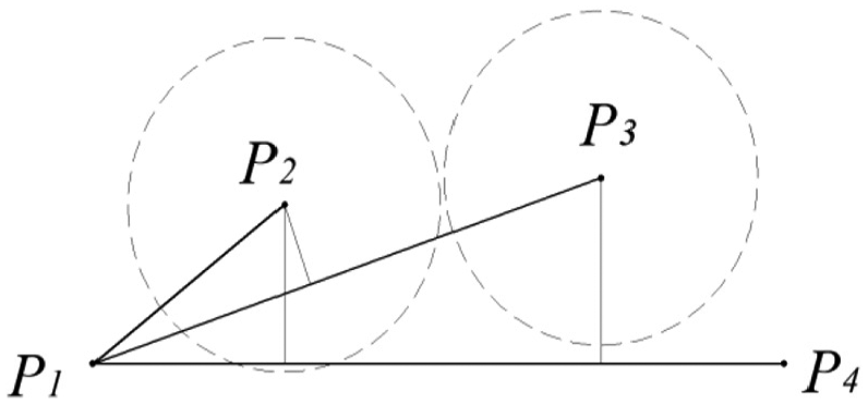
Contact point selection.
The method to determine whether the line P1P3 intersects with the error ball of point P2 is comparing the chord height d of the center of the error ball (P2 point) to the corresponding line and the radius of the error ball. If the error ball does not intersect the corresponding line, then d > r; otherwise, d < r.
Row spacing planning of strengthening path
A reasonable row spacing planning method of the strengthening path is needed in order to ensure sufficient and uniform ultrasonic strengthening for the turbine blade surfaces. As shown in Figure 4, the row spacing of the strengthening path along with the impact depth and feed rate together determine the uniform coverage of the surface ultrasonic strengthening for the turbine blade. The centerline of each path’s indentation should coincide with the edge of the previous path’s indentation, thus it can avoid under-strengthening and over-strengthening of the turbine blade surface. There are three conditions for the row spacing planning of ultrasonic surface strengthening, which, respectively, are plane surface, convex surface, and concave surface, as shown in Figure 5 and equations (10)–(12)


where

Row spacing of the strengthening path.

Three conditions for the row spacing planning of ultrasonic surface strengthening: (a) plane surface, (b) concave surface, and (c) convex surface.
Path planning simulation of robotic ultrasonic surface strengthening for turbine blades
Simulations are carried out on path points and row spacing planning of ultrasonic surface strengthening and on the pose of working head. First, it is necessary to establish the coordinate transformation relationship of robotic surface strengthening. As shown in Figure 6(a), the robotic world coordinate system

Coordinate transformation relationship of robotic surface strengthening: (a) establishment of each coordinate system, and (b) conversion relationship between the robot base coordinate system and the TCP coordinate system.
As illustrated in Figure 7,

Pose planning of working head.
On the basis of the coordinate system of robotic ultrasonic surface strengthening, the path planning simulation of the robot ultrasonic surface strengthening for turbine blades is conducted. The turbine blade model is shown in Figure 8(a). Figure 8(b) shows the planned path of ultrasonic surface strengthening. The path distribution of blade surface is uniform and the planning is reasonable.

Path planning simulation of robotic ultrasonic surface strengthening for turbine blade: (a) the turbine blade model, (b) planned path from the whole turbine blade and local enlarged drawing, and (c) contact coordinate system of each contact point.
The contact coordinate system of each contact point in Figure 8(c) can be used as the contact pose of the working head at each contact point, where the green line indicates the normal vector of each strengthening contact point, and the blue line and the red line indicate the tangent vectors at the point. It shows the distribution of contact points with different curvatures. It can be seen that with a small curvature, the strengthening contact points in relatively flat regions are sparsely distributed. And with a big curvature, the strengthening contact points have a relatively dense distribution. Since the path composed of the strengthening contact points is the processing path of the strengthening tool described in the workpiece coordinate system, it is necessary to convert it into the path of the end of manipulator by coordinate conversion in actual processing.
Conclusion
In this article, the research on path planning of robotic ultrasonic surface strengthening for turbine blade based on dynamic response of ultrasonic surface strengthening is presented. The main conclusions are as follows:
The nonlinear isotropic strengthening–kinematic hardening constitutive model for TC4 titanium alloy is analyzed. The model takes the strain hardening, strain hardening rate, and cyclic loading characteristics during ultrasonic surface strengthening into consideration, so the dynamic mechanical properties of TC4 titanium alloy can be reflected in the process of ultrasonic surface strengthening.
With the dynamic detection system, the dynamic impact force information actually received by the material surface during the machining process is obtained, and the finite element model of the impact motion for ultrasonic surface strengthening is established. The displacement information of the working head under ultrasonic impact is obtained by simulation. The maximum impact depth of the TC4 titanium alloy with ultrasound surface strengthening is 0.184 mm.
A path planning method of robotic ultrasonic surface strengthening for turbine blade is proposed on the basis of impact depth of working head, and it can improve both the uniformity of path distribution and contour accuracy. It can meet the requirement of the uniform coverage on the premise of guaranteeing processing efficiency and accuracy. This path planning method provides a new surface strengthening technology for turbine blades.
Footnotes
Handling Editor: James Baldwin
Author note
Qinjian Zhang is also affiliated to School of Mechanical and Electrical Engineering, Jiangxi University of Science and Technology, Ganzhou, China.
Declaration of conflicting interests
The author(s) declared no potential conflicts of interest with respect to the research, authorship, and/or publication of this article.
Funding
The author(s) disclosed receipt of the following financial support for the research, authorship, and/or publication of this article: The research work was supported by the Fundamental Research Funds for the Central Universities (grant no. 2018YJS135), the National Key Research and Development Program (grant no. SQ2019YFC010367), the Hongguoyuan National “Four Headquarters” Program (grant no. M18GY300021), the Science and Technology Landing Project in Universities in Jiangxi Province (grant no. KJLD14044) and the Talent Plan of Yangzhou in 2017 (grant no. CSJ-YZRC2018001).