
Abstract
In recent years, ultrasonic-assisted machining (UAM) has been widely implemented to improve the performance and element quality of machined products. This paper comprehensively reviews the ultrasonic vibration effects on such ultrasonic vibration-assisted (UVA) processes as hobbing (UVAH), lapping (UVAL), electrochemical gear machining (UVAEGM), honing (UVAH), and grinding (UVAG), respectively. Compared with the conventional machining, the UAM significantly reduced the surface roughness, improved the surface microstructure, and quality. Considering the UAM applications surface modification and surface strengthening, the available technologies of ultrasonic impact, ultrasonic shot peening, and ultrasonic deep rolling were analyzed for gears and similar components. It was concluded that the surface was strengthened under UAM through introducing the high-amplitude and large-depth residual compressive stresses, restraining crack propagation to a certain extent, and improving the gear fatigue resistance. Finally, the ultrasonic machining effect on gear fatigue resistance was theoretically substantiated from the ultrasonic vibration system and surface integrity standpoints. This review aims to optimize the application of ultrasonic-assisted machining, in order to produce gears with enhanced fatigue resistance and surface integrity.
Keywords
Introduction
Gear is a key component in the mechanical transmission system, which performance determines the safety and stability of the respective equipment. 1 Therefore, high-performance gears are integral parts of machinery used in aerospace, military applications, high-speed transport, new energy plants, ships, and other fields. Meanwhile, higher requirements for the high-performance gear manufacturing technologies are put forward, in order to increase gear speed, load capacity, reliability, and durability. In critical applications, available gears with a short service life, poor bearing capacity and unstable quality, etc., become the bottleneck in the development of high-end equipment.2,3 Therefore, manufacturing high-performance and high-durability gears for the complex heavy-duty working conditions has become an important challenge.
In the transmission process, gears bear altering and pulse tensile, compressive, and shear stresses, including the root bending fatigue, and tooth surface contact fatigue, wear, corrosion, and other types of damage and failure.4,5 In aero engine, catastrophic failures may occur, depending on the material, designation, manufacturing process, and maintenance. Once the gear fails in the transmission, the overall dynamic performance dysfunction may cause serious safety problems and catastrophic accidents, such as gear tooth breakage, drive system failure, power transmission interruption, and even catastrophic crash. 6 Gear failure may occur via a coupled failure mechanism, as shown in Table 1. 7
Failure mechanism of gear. 7

Moreover, the effect of the load and motion speed on the failure mechanism is shown in Figure 1. It was observed that the gear will fail under a certain load and motion speed.

Effect of load and motion speed on the gear failure. 7
Previous studies show that the main failure of gear is usually caused by tooth and/or root failure.8,9 Therefore, gear teeth surface integrity plays a decisive role in the gear service performance, including such indicators as longer life and lower noise. 10 These two factors should be comprehensively considered for the gear designation. On the one hand, in order to enhance the gear bending and contact fatigue resistances, it is necessary to adopt non-damaging mechanical processing technology. The hardness and strength of surface layer can be improved by carburizing, nitriding, and carbonitriding heat treatments,11,12 while the residual compressive stress can be introduced by shot peening or laser impact.13,14 On the other hand, a better surface finish of gear is beneficial for decreasing the noise during the gear meshing. Therefore, higher requirements for surface integrity are put forward in gear machining, as shown in Figure 2.

Design requirements for gear surface integrity. 10
Fatigue failure is characterized by low stresses and no macroscopic deformation in the failure process. Consequently, fatigue failure is one of the most dangerous failure modes, posing a serious threat during the gear service process. The gear surface state has a significant effect on its fatigue characteristics, so the tool marks, tissue damage, scratches, and other surface defects, can cause the local stress concentration and reduce the fatigue resistance, as shown in Figure 3. 15

Fatigue failure caused by discontinuous cutting marks. 15
About 80% of fatigue cracks initiate in the stress concentration sites, which crack initiation stage occupies over 80% of the total fatigue life of components. The local stress concentration promotes the initiation and propagation of cracks, sharply reducing the fatigue durability under cyclic loading. As shown in Figure 4, fatigue performance of components strongly depends on the surface integrity,16,17 including surface characteristics (roughness, waviness, texture, and defects) 16 and surface features (macro-cracks, micro-cracks, elastoplastic deformation, residual stress, micro-hardness, recrystallization, and phase transition).18,19 In addition, for the mechanical components, the surface integrity is vital for the fatigue and corrosion performance, as well as friction-abrasion performance, as shown in Table 2.21–23 Therefore, advanced manufacturing technologies based on the surface integrity optimization and enhanced fatigue resistance are very topical for prolonging service life and improving reliability and service capability of gears.

Schematic of machined surface integrity. 18

Ultrasonic assisted machining (UAM) has many advantages, such as stronger cutting ability, smaller cutting resistance, precise finishing ability, and better strengthening ability.24–26 During the process, it can reduce the cutting force and the chip thickness, enhance the cooling and lubrication effect of cutting fluid, effectively discharge chips and prolong the service life of tools, and reduce the surface roughness.27,28 Therefore, it can enhance the machining accuracy, improve the surface microstructure, wear resistance, and corrosion resistance.29,30 Simultaneously, UAM is an effective and energy regulation manufacturing process, wherein the external energy is effectively introduced to the surface, achieving the formative manufacturing with required shapes and characteristics. It can also realize the heredity and evolution of the surface microstructure under the action of external energy. Moreover, the manufactured shape precision, surface integrity, and the desired microstructure can be obtained through accurately regulated interface energy, eventually achieving the high-performance manufacturing goals of shape and property collaboration. The connotation of surface integrity under the action of ultrasonic vibration is shown in Figure 5.

Connotation of surface integrity for gears in the ultrasonic energy field.
Controlling the surface integrity and deterioration of surface layers of the machined workpiece, the scientifically substantiated manufacturing technology can achieve high fatigue strength of gears.2,31 Such “anti-fatigue” manufacturing technology of gears should comprise five aspects, namely gear material design, gear macro- and micro-morphology design, gear heat treatment, gear grinding and finishing, and surface enhancement. A flowchart of such comprehensive gear manufacturing system is shown in Figure 6. However, few systematic investigations on the effect of UAM on the gear surface integrity. In order to promote the application of UAM on the gear machining, firstly, the paper comprehensive review the ultrasonic vibration-assisted processing gear, and surface strengthening methods. Then, the development of ultrasonic machining in gear fatigue resistance was proposed.
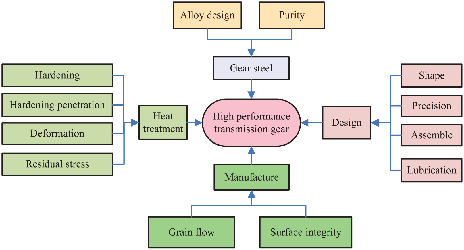
Comprehensive gear manufacturing system.
Current status of ultrasonic-assisted machining technology
Ultrasonic machining is a non-conventional mechanical material removal process, which was introduced in 1950 by Kumabe for machining both metallic and non-metallic materials. 32 During the processing, the tool vibration causes the abrasive particles held in the slurry between the tool and workpiece to impact the workpiece surface causing material removal by micro-chipping. 33 Combined with the conventional machining processes, various compound process technologies with ultrasonic vibration have been developed,34–36 as shown in Figure 7.
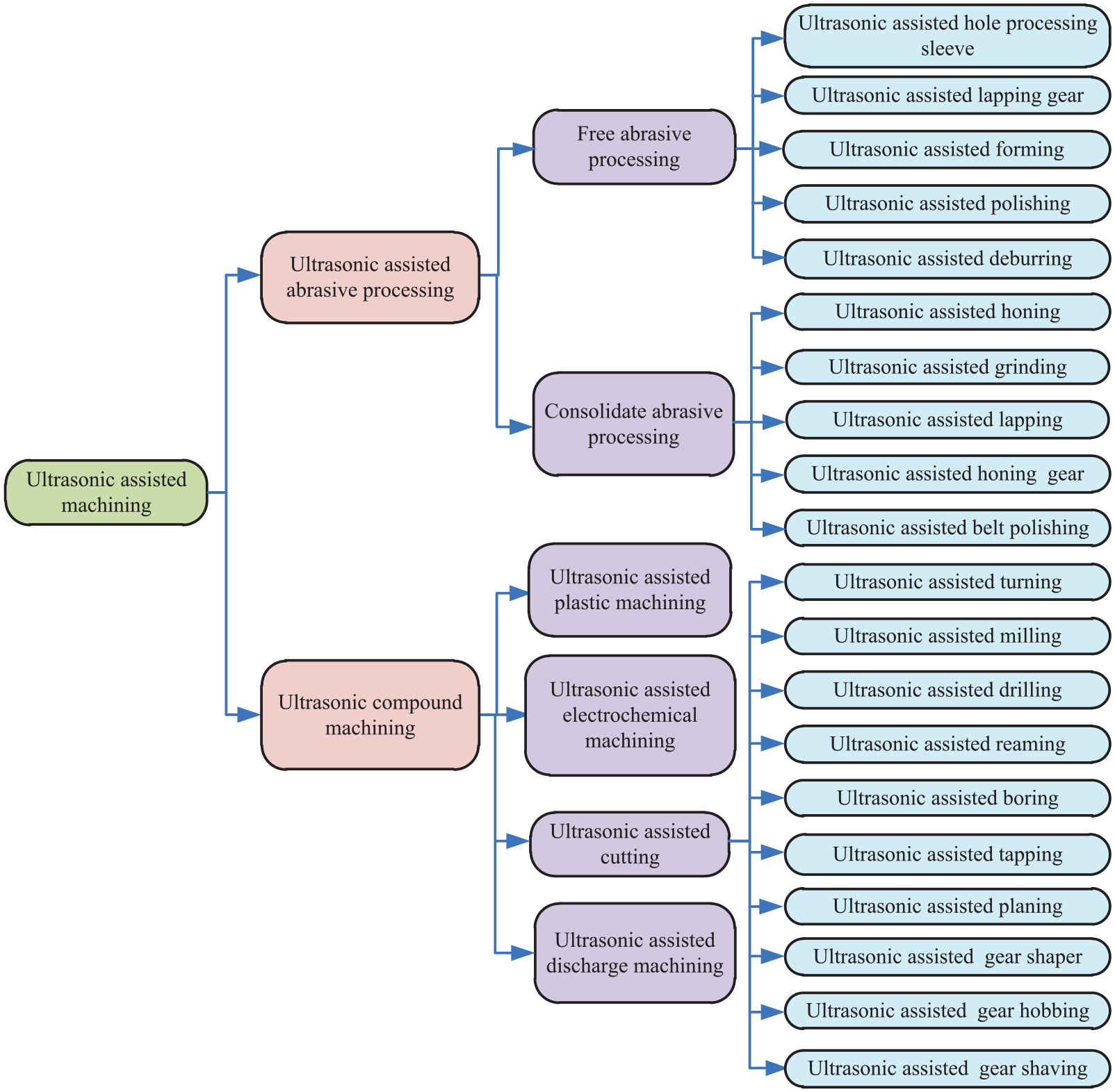
Classification of ultrasonic-assisted machining.
As shown in Figure 8, only a few publications in EI- and SCI-indexed journals appeared before 2000, exhibiting a linear increase, followed by an exponential one after 2000. As seen in Figure 8, in the past 20 years, about 525 SCIE papers and 1250 papers on UAM were retrieved, with a ratio of about 1/3.
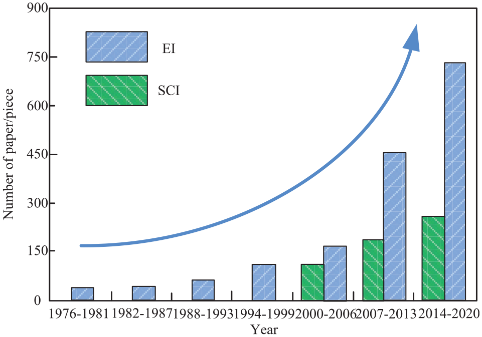
Retrieval paper on ultrasonic assisted machining.
According to the distribution of relevant publications by countries, the prevailing number of such papers was published in China, as shown in Figure 9. As the origin of ultrasonic vibration research, Japan had obvious advantages, but was only the second-best in this competition. The number of papers from Europe and USA kept rising. In recent years, the basic research on ultrasonic processing in India, Iran, Korea, and Russia has also been intensified.

Distribution of SCI and EI-indexed publications on ultrasonic assisted machining by countries.
With the development of UAM, it was widely incorporated into various processes, such as cutting, grinding, and non-conventional machining. The compound processing technologies with ultrasonic vibration have gradually become one of the most important means to improve the machining efficiency and accuracy. It has been increasingly applied to new materials, difficult-to-machining materials, high surface integrity, and bionic manufacturing.37–40 According to its effectiveness, UAN can be mainly subdivided into three categories, namely (i) vibration cutting, (ii) vibration finishing, and (iii) vibration strengthening,41–46 whose main characteristics and application fields are shown in Figure 10.

Application fields of ultrasonic assisted machining.
Review on ultrasonic compound machining of gears
During the development of gear, high performance requirements of high precision, high speed, low noise, long service life, and heavy load, etc., have become the trend of gear manufacture.6,47,48 Based on the requirements of high performance gear, ultrasonic vibration was comprehensively combined with conventional gear-processing methods, and achieving ultrasonic hobbing, ultrasonic shaving, ultrasonic gear shaping, ultrasonic honing, ultrasonic electrochemical machining, and ultrasonic gear grinding. The action of ultrasonic vibration dramatically enhanced the surface quality, microscopic geometry, surface integrity, and fatigue resistance.
In the 1970s, Prof. Kumabe from Japan briefly introduced the ultrasonic vibration-assisted hobbing (UVAH), ultrasonic shaving gear, and ultrasonic gear shaper in his monograph. 49 Later, multiple machining processes, such as vibration gear rolling using a comb gear cutter, vibration gear shaper with a slotting cutter, hobbing gear with the help of torsional vibration, vibration gear-shaping with double cutter, vibration grinding gear with disk wheel and worm wheel, and vibration rolling gear with longitudinal vibration gear roll, appeared and become quite popular. In 2016, Jain and Petare 50 investigated the effect of conventional gear machining and ultrasonic precision machining on the surface quality, microscopic geometry, surface integrity and fatigue resistance, as well as studied the operational performance (meshing, noise, wear characteristics, and service life). It was concluded that the suitable machining process was beneficial to optimize wear and fatigue characteristics, and increase service life and load capacity of gear.
Ultrasonic vibration-assisted hobbing gear
In 1995, Yin and Zhang 51 conducted the conventional hobbing (CH) and UVAH of gear using an YM3150 precision hobbing machine. The test gear materials, tools, feed rates, and surface roughness values in the two processing methods are summarized in Table 3. Compared with the conventional hobbing, the cutting force and cutting temperature in the UVAH was effectively reduced, restraining built-up edges, and development of scales. The gear surface roughness was reduced by one to two grades, while the hob service life was prolonged. In 2001, Luo 52 superimposed ultrasonic vibration system with gear hobbing machine (YBA3132) to conduct ultrasonic gear hobbing test. The machined gear with modulus of 4.5 mm and 34 teeth was produced from 20CrMnTi steel with hardness HRC = 12–21. It was concluded that UVAH improved gear-processing conditions, reduced the surface roughness, and saved the material, energy, and costs.
CH and UVAH processing parameters.

From 2007 to 2010, Agapov53,54 conducted the ultrasonic gear hobbing through a piezoelectric transducer to provide ultrasonic vibration to the gear. During the test, an R6M5 hob was used to machine the gear from 40 Kh steel. The relationship between gear cutting efficiency, tool life, and cutting speed was obtained. With the help of ultrasonic vibration, the efficiency of hobbing was improved, and the service life of cutting tools was increased by 1.6–1.8 times. As shown in Figure 11, the variation ultrasonic amplitudes and vibration directions also influenced the machining effect. The optimal results were obtained at the ultrasonic amplitude of 4–6 μm and the ultrasonic frequency of 18–22 kHz.

Relationship between vibration direction and tool life: (a) experiment setup and (b) experimental results.
In 2015, Qin et al. 55 developed an ultrasonic gear hobbing device composed of the gear rotation structure, ultrasonic vibration system, support and fixed system, and reversing system, combined with the hobbing machine’s worktable. According to the gear structural characteristics, the corresponding vibration forms and tool feed modes were adopted to provide the gear machining. The results showed that the developed ultrasonic gear hobbing device could prolong the hob service life, improve the precision of hobbing and the texture of tooth surface, reduce the noise, and enhance the wear resistance.
Ultrasonic vibration-assisted lapping gear
In 1990, Norio and Shigeyuki 56 patented the gear tooth flank finishing method by ultrasonic waves. During the processing, the cutting fluid flew into the meshing zone between the lapping gear and machined gear through the ultrasonic vibration device. Under the ultrasonic cavitation effect, the cutting fluid could effectively improve the processing conditions, release the main lapping gear congestion, and prolong its service life. From 2004 to 2008, Wei et al.57,58 applied for the utility model patent of a kind of gear lapping machine for the precision ultrasonic vibration-assisted lapping small-modulus bevel gear, and also proposed the theory and method for the processing. The UVAL test was conducted for gear modulus of 1.25 mm and gear ratio 17/44, with the lapping fluid made from a mixture of water and W40 # white corundum. The experimental results proved that the material removal mechanism under ultrasonic vibration was coupled with hammer, collision, and cavitation effects. The material removal rate was three times higher than that of conventional lapping (CL). As shown in Figure 12, the microscopic indentation, micro-cutting, and plastic flow texture of the tooth surface was uniform, and the quality of tooth surface was improved by the UVAL.

SEM photograph of the lapped tooth surface 58 : (a) UVAL and (b) CL.
From 2008 to 2010, Yang et al.59,60 established the dynamic model of UVAL spiral bevel gear system with ten degrees of freedom, including tooth side clearance, transmission error, and mesh stiffness, as shown in Figure 13. In the figure, axes
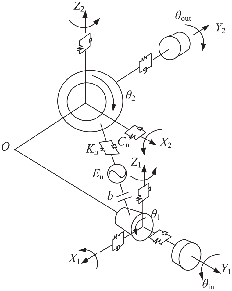
Dynamic model of gear lapping system. 60
Contrast experiments of CL and UVAL.

In 2013, Yang et al. 61 designed the ultrasonic lapping hypoid gear and obtained the ease-off topography of gear. It can be seen in Figure 14 that due to any contact flank materials being removed during the UVAL, the flank deviations were minimized after UVAL, and the contact area was enlarged. Thus the gear set would be less noisy due to its wider contact area.
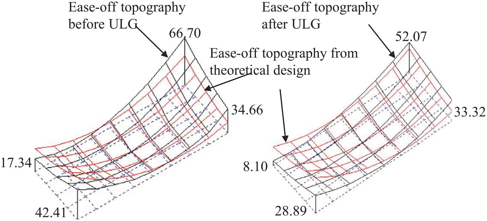
Comparison of ease-off topography between CL and UVAL. 61
In 2015, Venkatesh et al. 62 employed the ultrasound-assisted abrasive flow machining (UAAFM) to achieve the processing of bevel gears. A 3D model was constructed to simulate the media flowing through the gear tooth surface using the finite element method (FEM). Then, the velocity, pressure and temperature values along the gear length were calculated by the computational fluid dynamics method for UAAFM and conventional abrasive flow machining process. As shown in Figure 15, the surface finish of tooth surface was effectively improved with the extension of grinding time. Moreover, the mechanism of material removal was obviously changed. In a certain processing time, the active abrasive process was enhanced, significantly improving the tooth surface morphology. Therefore, as shown in Figure 16, the microstructure of gear tooth surface was significantly improved, and a smooth texture was obtained.

Effect of processing time on surface finish improvement. 62

Typical SEM micrographs of gear tooth surface: (a) before UAAFM and (b) after UAAFM. 62
In 2019, Zhu et al. 63 conducted ultrasonic lapping gear on the modified rolling inspection machine (Y9550). The results showed that under the action of ultrasonic vibration, the tooth surface error could be eliminated to a certain extent, the position and shape of contact area of gear, the tooth surface smoothness, and the quality of gear were improved.
Ultrasonic vibration-assisted electrochemical machining gear
In 2006, Pa 64 processed the gear with ultrasonic vibration-assisted electrochemical machining (UVAEM). In the experiment, three type electrodes of A, B, and C were designed, and the processing parameters are shown in Table 5. The best machining effect was obtained using the C-type electrode (the same shape as the gear teeth being machined), an ultrasonic vibration frequency of 120 kHz, a power of 80 W, the current of 20 A, and a feed rate of 4.0 mm/min. Compared with the conventional electrochemical machining, the surface roughness Ra of UVAEM-processed gear was lower, reaching 0.3–0.7 μm.
Parameters of ultrasonic-assisted electrochemical gear.

In 2011, Jia et al.65,66 studied on ultrasonic combined electrochemical machining for micro-gears. In the experiment, the GCr15 steel was selected as the machining tool and the 40Cr steel as the cathode material to machine gear of YBD151 carbide. The abrasive was B4C-W5 and the electrolyte was 5% NaNO3 solution to conduct the microgear ultrasonic machining, ultrasonic combined electrochemical machining, and ultrasonic combined synchronous pulse electrochemical machining. The results showed that the microgears obtained by the third method had high precision, excellent surface quality, tooth profile accuracy up to ±0.005 mm, and tooth surface roughness Ra up to 0.16 μm.
In 2018, Singh67,68 investigated on ultrasonic electrochemical honing (UECH) bevel gear. During the experiment, joint cathode gear and honing wheel were employed in an UECH AISI1040 bevel gear. It was concluded that the average surface roughness Ra and maximum surface roughness Rt increased with ultrasonic frequency. At the ultrasonic frequency of 42 kHz, Ra and Rt reached their optimal values of 0.31 and 6.88 μm, respectively. As shown in Figure 17, the surface texture become smooth and the surface finish was significantly enhanced.

Micro-topography of gear surface 67 : (a) before UECH and (b) after UECH.
Ultrasonic vibration-assisted honing gear
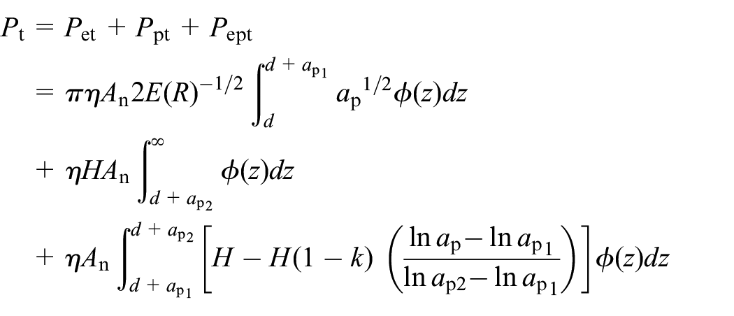
In 1996, Chen et al. 69 investigated the worm vibration honing hardened gear using a honing machine (YM3180H). During the experiment, the surface of the Archimedes worm was homogeneously electroplated by synthetic diamond abrasive, and the worm was taken as the honing wheel in the UVAH. It was discovered that the waviness along the axial feed direction and gear surface could be effectively reduced, while the machining efficiency was increased by two times. In 2006, Lü et al. 70 combined ultrasonic vibration with honing process and proposed an ultrasonic vibration-assisted honing technology. Lü and Wang71–74 proposed a design theory and method of ultrasonic vibration system for ultrasonic vibration-assisted honing of gears with hard tooth surface, while displacement characteristics were varied by a bending vibration transformer. The system could improve the gear honing processing parameters, increasing cutting speed, and reducing honing force. In addition, the cavitation effect of cutting fluid in the process provided the dynamic cleaning of the honing wheel, improving its working conditions. Therefore, the tooth surface roughness was significantly reduced, and the precision of tooth profile was improved. Li and Qin75–78 studied the material removal mechanism of ultrasonic honing, where the pulsed cutting force model of a single abrasive was established as follows.

where
On the basis of honing force, the model of material removal rate for the ultrasonic honing was established:

where
Compared with conventional honing gear, the material removal volume per unit time significantly increased in ultrasonic vibration-assisted honing, the honing force was decreased, and the tool service life was prolonged. In addition, the microcutting wave of the tooth surface became more pronounced, while the gear surface texture and surface quality were improved, as shown in Figure 18.
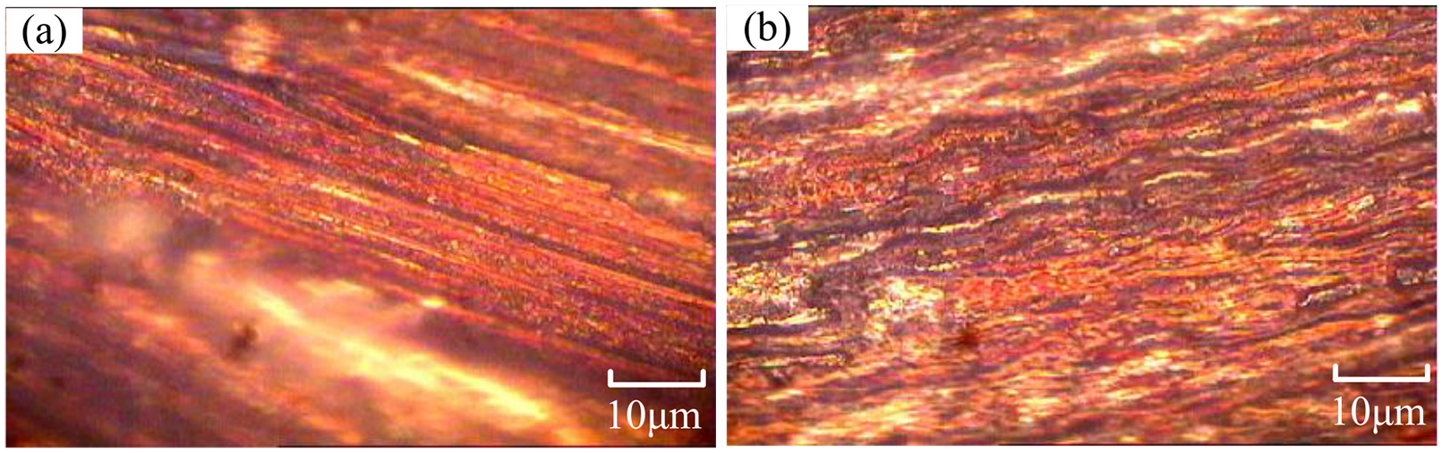
Microphotograph of honed tooth surface 77 : (a) CH and (b) UVAH.
Ultrasonic vibration-assisted grinding gear
Zhao et al.
79
proposed the ultrasonic vibration-assisted forming grinding gear, and investigated the thermo-mechanical coupling effect on surface residual stress. It was found that the surface residual compressive stress gradually decreases with the increase in spindle speed, while it increases first and then decrease with the increase in ultrasonic amplitude. Comparing with the conventional grinding gear, the average rate of increase of the surface residual compressive stress under the both parameters is 17.8%–31.3% and 20% respectively. Bie
80
proposed the tangential ultrasonic vibration-assisted gear grinding (TUVAGG) method, combining ultrasonic machining with conventional gear grinding. During the TUVAGG process, the forming wheel grinding was used to trim the grinding wheel into an inverse surface, which was completely consistent with the profile of the machined gear. Thus, the forming wheel was prepared or dressed according to the gear profile. Figure 20 illustrates the TUVAGG procedure, with the ultrasonic vibration superimposed on the machined gear to generate the longitudinal vibration. As shown in Figure 19, the grinding wheel axis is normal to the gear axis, and the center of the grinding wheel’s truncation coincides with that of the grinded tooth groove. The gear is superimposed on ultrasonic vibration, with an ultrasonic amplitude
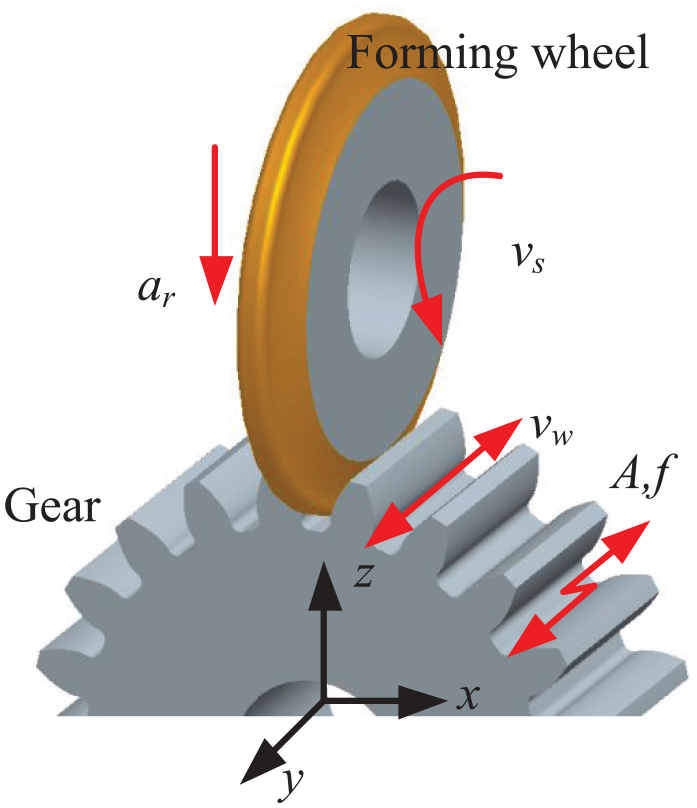
Schematic of tangential ultrasonic vibration-assisted grinding gear.
The grinding forces under the conventional grinding gear (CGG) and TUVAGG was obtained by changing the machining parameters. As shown in Figure 20, compared with CGG, TUVAGG could reduce the normal and tangential grinding forces by 7.4%–28.2% and 8.9%–18.9% respectively. Figure 21 presented the trend of residual stress under different parameters. The TUVAGG could enhance the residual compressive stress by 13.2%–29.3% compared with the CGG. 81
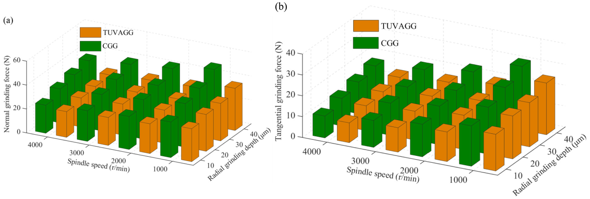
Influence of grinding parameters on the grinding forces: (a) normal grinding force and (b) tangential grinding force.
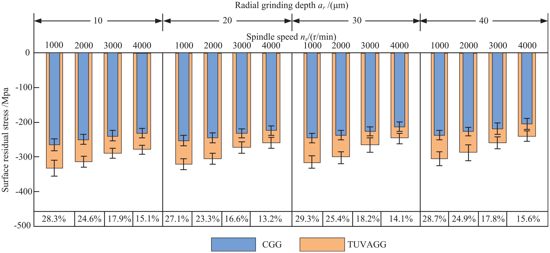
Trend of residual stress on the tooth surface.
Yin et al. 82 established the analytical modeling of grinding force on ultrasonic vibration-assisted forming grinding gear, and obtained the effect of processing parameters (ultrasonic amplitude, grinding wheel speed, grinding depth, and feed speed) on the grinding force. This results provided a reference for the investigation on the ultrasonic vibration-assisted grinding gear.
The above investigations declared that the combination of ultrasonic machining and conventional machining can achieve the effect that the latter cannot achieve. Compared with the conventional machining, the cutting force and gear teeth surface roughness can be reduced, and the tool’s service can be lengthened under the behavior of ultrasonic vibration. However, the processing effect was only obtained by the experiment, and the machining mechanism cannot be further investigated. Besides, the different processing makes it difficult to evaluate consistently. This limits the application of UAM on gear. Therefore, the general theoretical model should be established considering gear parameters and processing parameters. In addition, the effect of ultrasonic vibration on gear fatigue resistance need to be further explored.
Review on ultrasonic reinforcement of gear
The surface integrity of gears has a significant impact on the wear resistance, corrosion resistance, and transmission capacity. Surface strengthening technology is aimed to produce a new surface of a part different from the performance of the raw material through transferring different materials and energy to the surface. This can make the performance changed so as to improve its functional requirements of fatigue resistance, wear resistance, and corrosion resistance. 83 Ultrasonic reinforcement technology is one of the most effective surface-strengthening methods. It can improve such gear performance characteristics the fatigue limit, bending fatigue life, oxidation resistance, corrosion resistance, and surface hardness.
Ultrasonic impact technology
Ultrasonic impact technology (UIT) is driven by ultrasonic vibration, and converts electrical energy into mechanical energy through a transducer. After amplification by the transformer, the tool impacts the surface at a high frequency, causing plastic deformation of the surface and introducing residual compressive stresses, and thus improving the fatigue resistance of the part.84,85 The UIT can break out the material type and structure limitation, and is beneficial for the gear strengthening. 86
In 1985, Dankov
87
studied the abrasion resistance and contact fatigue life of a small-module gear processed by the UIT. In the process, the tool was employed to impact the surface under ultrasonic vibration. After ultrasonic impact surface treatment, the surface quality was significantly improved, the surface roughness was reduced, large residual compressive stresses were generated, and thus the abrasion resistance and contact fatigue resistance were obviously enhanced. Yin et al.
88
strengthened the 20Cr2Ni4A carburized gear steel by the UIT. The results showed that after ultrasonic impact, the mechanical properties and microstructure of the material were significantly improved, the grain size was refined, while the residual compressive stresses and the surface micro-hardness were significantly increased. Daavari
26
conducted ultrasonic impact strengthening tests on A106-B hypereutectoid steel. It was concluded that the steel surface underwent grain refinement and residual compressive stress generation, while the hardness and fatigue resistance increased by 33% and 99.4%, respectively. In 2016, Lei and Guo89–92 used UIT to strengthen AISI304 austenitic stainless steel. They established the relationship between the impact force

According to the variation of ultrasonic frequency and amplitude, the energy input the ultrasonic impact can be accurately calculated, and the trend of impact force, residual stress, and fatigue performance can be obtained, as shown in Figure 22. In ultrasonic impact processing, with an impact velocity of 12 m/s, the corresponding impact force was 2.5 kN, and a compressive stress layer was formed at a depth of 400 μm from the surface. The peak compressive residual stress of −550 MPa was observed at the depth of 100–200 μm, which was more than twice higher than that before UIT. This increased the endurance limit the workpiece from 240 to 380 MPa and enhanced the fatigue life by nearly two orders of magnitude (105–107 cycles). The results showed that the generation of residual compressive stress by ultrasonic impact could inhibit the initiation and delay the propagation of fatigue cracks, improving the fatigue resistance.

Surface strengthening of ASSI304 steel by UIT: (a) mechanical load, (b) residual stress, and (c) fatigue resistance.
Based on the fully plastic contact theory, Wu et al. 93 conducted a FEM analysis of impact stresses under multi-parameter, coupling conditions, and analyzed the energy variation during ultrasonic impact, as shown in Figure 23. During the processing, the plastic dissipation and strain energy values changed periodically, resulting in plastic deformation of the surface and formation of a nanocrystalline layer.

Evolutions of artificial strain energy (ASE), frictional dissipation (FD), internal energy (IE), kinetic energy (KE), plastic dissipation (PD), strain energy (SE), total energy (TE), and viscous dissipation (VD) during ultrasonic impact.
Lu et al. 94 reported that during the grinding process, the surface layer of nickel-based alloy materials could achieve a two-dimensional nanoscale lamellar structure, as shown in Figure 24. Its thickness was about 20 nm, had a micro-hardness of 6.4 GPa, and this structure was very stable at high temperatures. Therefore, nanoscale structures generated on the surface significantly improved the corrosion resistance and fatigue resistance of materials.95,96
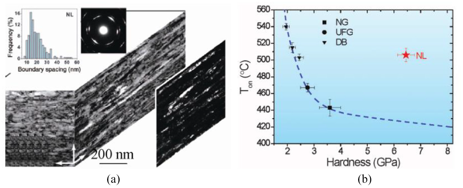
Surface nanostructure and physical properties of nickel-based alloys 94 : (a) layer-shaped nanostructures and (b) correlation of thermal stability and hardness.
Numerous studies have shown that the creation of surface nanoscale structures by UIT improved the surface hardness, surface residual compressive stress distribution, and wear resistance.97–99 The parameters influencing the UIT effect mainly include static load, 100 number of impact times per unit area, 101 amplitude, 102 etc. The surface characteristics of materials after UIT are listed in Table 6. At different impact parameters, ultrasonic impact significantly increased the surface hardness and residual compressive stresses.
Ultrasonic impact effect on the surface properties of materials.

Because the ultrasonic impact is based on mechanical treatment, some defects such as impact marks and slight plastic pile-up, are inevitable during UIT. When the workpiece is subjected to alternating loads during service, the microcracks will appear in the defects, deteriorating the fatigue resistance of the workpiece. Considering the complexity of gear structure, several researchers explored the ultrasonic impact processing of gear, which proved the advantages of UIT, and recommended it as a novel processing method of gear machining, provided that other related factors were comprehensively adjusted.
Ultrasonic shot peening technology
Ultrasonic shot peening (USP) is a surface strengthening intensification technology, which envisages surface peening by numerous metal (ceramic) pellets over a short period of time, combined with the ultrasonic vibration.106–108 In the USP, the tool is driven by high-frequency vibration via a transducer, and then pellets are driven to impact the surface in the closed chamber, while the motion direction and velocity of pellets are randomly distributed.109,110 Compared with conventional shot peening, the USP process can induce deeper hardened layers 111 and generate larger residual compressive stresses. 112 Since the pellets repeatedly impact the material surface at a high speed, dislocations will occur on the surface, forming irregular microcrystals, which will lead to the generation of nanospheres. 113
Yan 114 derived the pit depth after USP as follows.
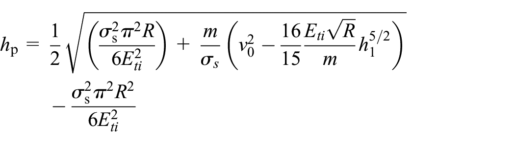
where
Based on the Iliushin elastic-plastic theory, the model of final residual stress with 100% coverage of USP was established by Li et al. 115 as follows :

where
At present, the USP mechanism was analyzed by numerous scholars worldwide. In 2005, Zhao 116 reported that the low-cycle fatigue strength of ultra-high strength steel after USP was increased by about 50%, and the high-cycle fatigue strength of Ti7Al4Mo alloy grew by about 15%, while the contact fatigue life of gear steel could be extended via USP by 30–35 times. Ramos et al. 117 adopted USP to machining of AA7475-T7351 alloy with an ultrasonic frequency of 20 kHz and a metal pellet’s diameter of 1–2 mm. It was observed that USP significantly improved the surface finishing and reduced the surface roughness. The residual compressive stress with an average value of −235 MPa was generated on the surface, and the fatigue life increased by 21.4%–23.9%. As shown in Figure 25, the crack propagation of the workpiece could be effectively restrained, improve the fatigue resistance.

The SEM image superimposed on the USP-induced residual stresses profile. 117
Kulekci and Esme 118 and Regoet al. 119 employed the ultrasonic shot peening device (Figure 26) to gear machining. It could increase the depth of the tooth subsurface layer with the peak compressive stress by two to four times compared to conventional shot peening. In addition, the surface strength was enhanced, wear resistance, and corrosion resistance were also improved, and thus the fatigue life was prolonged.

The schematic of USP surface strengthening of gears.
Rakita et al. 120 and Chen et al. 121 reported that during the USP process, a large amount of energy was introduced into the material after the high-frequency impact of pellets on the surface. This could achieve the surface nanoization effect, inhibiting the initiation and propagation of fatigue cracks, and improving the fatigue resistance of the workpiece. In 2002, Hattori et al. 122 investigated the gear surface and tooth root strengthening by USP. After the processing, as shown in Figure 27, residual compressive stresses were generated in the gear surface and root, which magnitudes were two to four times higher than those of conventional shot peening. The surface roughness and surface quality were also improved.

Residual stress distribution in the gear tooth after USP. 122
To evaluate the USP dynamic model of gear, the Event-Driven-Dynamics algorithm was adopted by Badreddine et al. 123 The effect of shot peening parameters (pellet diameter, ultrasonic amplitude, coverage, and shot-peening time) and the chamber geometry on the impacts velocity (speed and direction) was obtained by the dynamic model. Then, the verification experiment was conducted with the experimental setup in Figure 28. Comparing the simulation and experimental results, as shown in Figure 29, the ultrasonic amplitude and pellet (shot) diameter were found to play an important role in shot-peening velocity and effect.
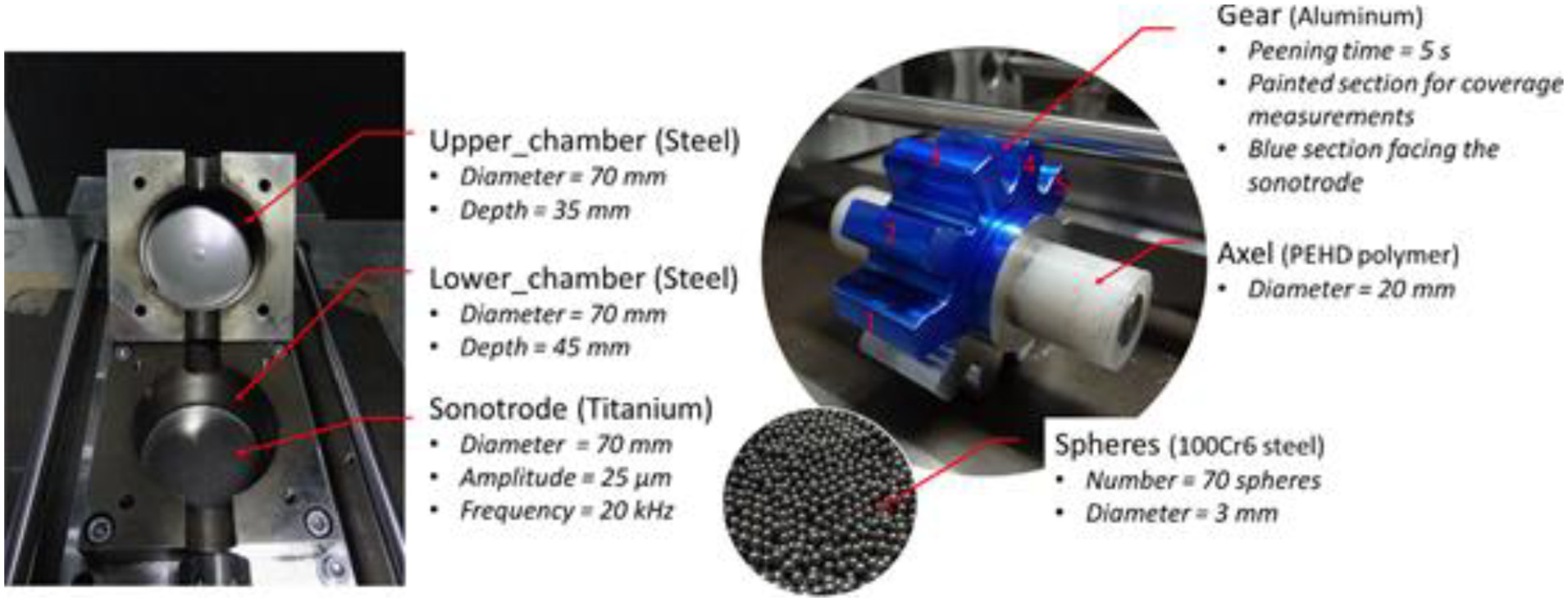
Experimental setup and parameters used for the model validation. 123

Qualitative comparison of experimental (left) and numerical (right) spatial impact distributions in the gear lower section. 123
The above review shows that a few available reports on USP of gear are mainly concerned with qualitative research of the gear performance after shot-peening, while scare quantitative studies revealed the relationship between shot-peening parameters and the fatigue resistance, which depended on many parameters. The selection of shot-peening parameters had a significant effect on the gear surface integrity. Therefore, it is particularly important to choose the optimal process parameters according to the required gear performance.
Ultrasonic deep rolling technology
Ultrasonic deep rolling technology combines ultrasonic vibration with the deep rolling processing method. Under the action of ultrasonic vibration, the great impact force is generated, and high residual compressive stress is introduced into the deep surface, also reducing the surface roughness value and achieving surface reinforcement.124,125 The principle of ultrasonic deep rolling is presented in Figure 30. The tool head applies the superimposed ultrasonic vibration and a certain static pressure to surface, providing a high-frequency vibration. In the processing, the residual compressive stress can be produced on the surface and achieve the purpose of refining grain size. 48
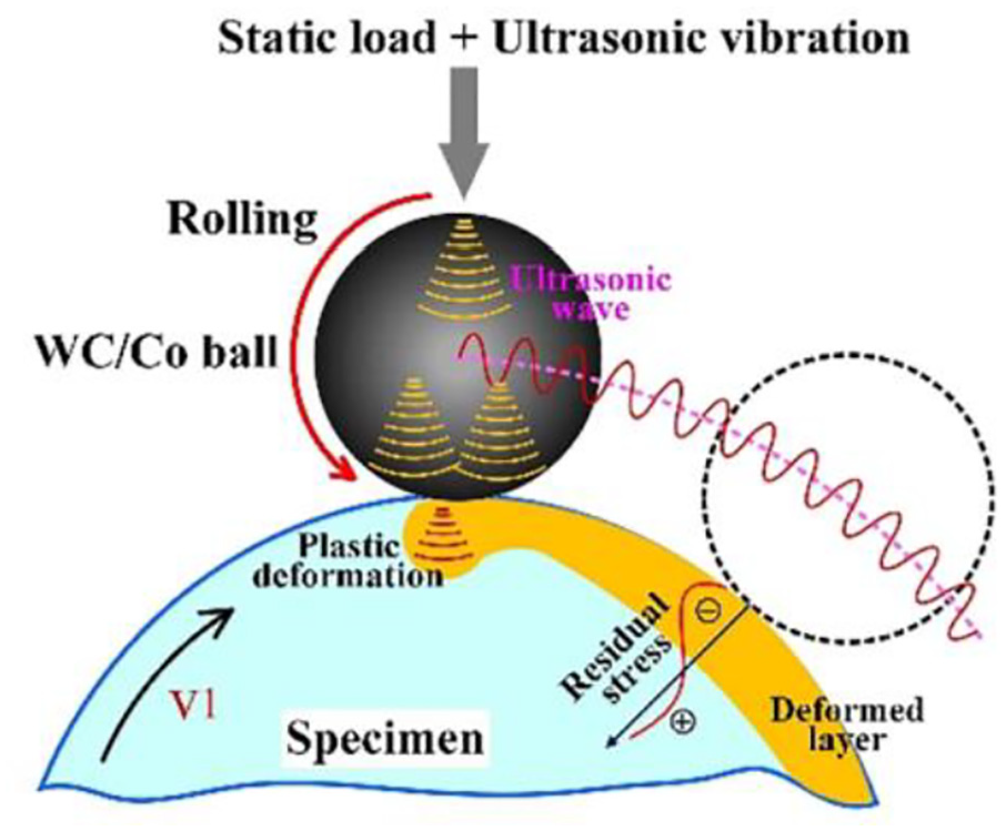
Schematic of ultrasonic rolling technique. 48
In the processing, the rolling pressure plays an important role in the rolling effect. According to the Hertz contact theory, Luo et al.
126
established a mathematical model for the contact pressure
where
Zhao et al. 127 established the model of ultrasonic rolling pressure and rolling depth based on the Hertz contact theory, and experimentally verified their linear relationship. Lü et al. 128 and Zhu et al. 129 conducted the TC4 titanium alloy reinforcement via the ZXZ-40A CNC lathe with the ultrasonic deep roll surface strengthening system, and then carried out the constant-stress cyclic test via a PQ1-6 rotary fatigue test machine with a stress ratio R = −1. It can be observed in Figure 31 that the endurance limit at 107 cycles of the specimen before ultrasonic deep rolling was 362 MPa, while after the strengthening it grew to 612 MPa, that is 69.1%. This extended the fatigue life at stress amplitude of 600 MPa by about 100 times.

Fatigue life curve before and after ultrasonic deep rolling. 129
Zhang et al. 130 studied the corrosion resistance of nanocrystallization surface of 20CrMnTi treated with ultrasonic rolling. During the ultrasonic rolling process, the surface grains of 20CrMnTi significantly differed in refinement within the local micro-region. Under the electrochemical action, the difference of micro-region potential between refined grains would lead to selective dissolution on the surface, and generate corrugated local corrosion pits at the folding interface of grains. In addition, the corrugated corrosion pits would significantly widen and deepen with an increase in ultrasonic rolling pressure, which promoted fatigue crack initiation.
Zhang and Zhao 131 utilized the ultrasonic rolling equipment to strengthen the 45# steel surface. The surface microstructure was obviously improved by the processing. The surface roughness value of 3.2 μm before processing dropped to 0.23 μm, the surface was hardened, and the depth of hardening layer reached 400 μm. The surface micro-hardness exceeded the bulk one by 56%. The residual compressive stress changed from −180 to −532 MPa, and the endurance limit grew by about 36%.
Tolga Bozdana et al. 132 and Tsuji et al. 133 used a special device to apply a 20 kHz high-frequency vibration through the ultrasonic generator and static pressure to the work pin, continuously contacting with the Ti-6Al-4V surface. The processing was a nearly frictionless rolling processing. It was observed that the applied static pressure was lower than that of conventional processing, the surface plastic deformation, residual compressive stress amplitude and depth were significantly increased, and the surface was obviously hardened. Moreover, as shown in Figure 32, the fatigue strength was enhanced, and the crack propagation was inhibited, improving the fatigue resistance.

Surface before and after conventional deep rolling (a) and ultrasonic deep rolling (b). 132
Wang et al. 134 studied the fatigue resistance mechanism of electropulse-assisted ultrasonic surface rolling (EP-USRP) of the AISI304 stainless steel and revealed the fatigue evolution mechanism, as shown in Figure 33. Under the ultrasonic surface rolling conditions, the grain arrangement of the material was regular, and its grain size was larger, while numerous micro-cracks existed in grains. Moreover, a large number of micro-cracks were generated in the subsurface, instead of the workpiece surface. After the EP-USRP, the grain was refined and exhibited a stepped distribution. Due to the electric pulse effect, the residual compressive stresses increased and the micro-cracks were passivated, effectively inhibiting the crack initiation and increasing the depth of the fatigue source.
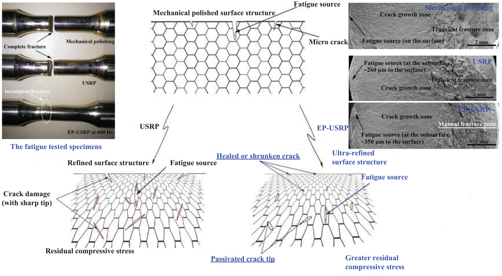
Schematic illustration of the fatigue process evolution in the AISI 304 stainless steel under the action of EP-USRP. 134
In order to realize the high efficiency, low surface roughness and large residual compressive stress manufacturing of 12Cr2Ni4A gear steel, Jiao et al. 135 analysis the processing parameters on residual stress. It was found that the surface residual compressive stresses firstly increased and then decreased along the direction of rolling depth. As the static forces increased, the peak of compressive residual moved from surface to substrate, the maximum residual compressive stress was −654 MPa, and the thickness of hardness layer was about 0.8 mm.
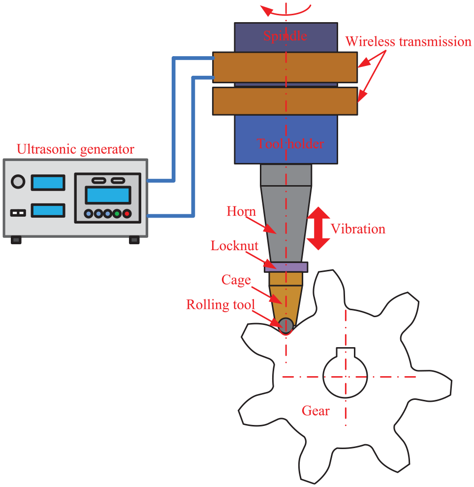
Based on the ultrasonic rolling strengthening technology and the involute generating method, Song and Chen136–138 developed the ultrasonic rolling device for gear surface strengthening, as shown in Figure 35. The gear with a 3 mm modulus, and 20 teeth was reinforced during the experiment. It was concluded that the hardness and residual stresses of the gear surface were significantly increased, the surface roughness value was reduced, and the tooth profile accuracy was improved. Zhao 139 adopted the ultrasonic reinforcement device (shown in Figure 34) to strengthen the gear surface. Due to the complexity of tooth surface, one side of the gear surface can be strengthened, and the other side needs to be second installation. This decline the machining efficiency and the gear surface accuracy is difficult to guarantee. 140

The schematic of gear ultrasonic reinforcement.
Fujisawa and Komori141,142 designed a set of tool gears made of alumina-fiber-reinforced plastic (ALFRP), as shown in Figure 35. Under the action of low-frequency vibration, the gear surface after heat treatment was rolled to eliminate burrs and pits. The results showed that the surface finishing and surface quality were improved. The maximum roughness Rz along the tooth profile after rolling decreased from 0.51 to 0.40 μm, and the Rz along the tooth width dropped from 2.00 to 0.27 μm.

Experimental setup of gear tooth processing with oscillation generator. 141
Lan 143 developed the ultrasonic vibration system suitable for gear root rolling, as shown in Figure 36. The contact between the rolling tool and the tooth root surface was described by the following relation:

Schematic of experimental device ultrasonic strengthening tooth root.
where
The effect of process parameters on the contact of area coefficient is illustrated in Figure 37. The contact of area coefficient increased with the interval and ultrasonic amplitude, while decreased with the rolling force and feed rate. The residual stress on the root surface was measured via a PROTO X-ray tool using the XRD method, and the effect of process parameters on the residual stress along the gear’s circumference and axial direction was revealed. It was concluded that the residual compressive stress was introduced in the processing, which linearly increased with rolling force, while the axial and circumferential residual stresses tended to stabilize.
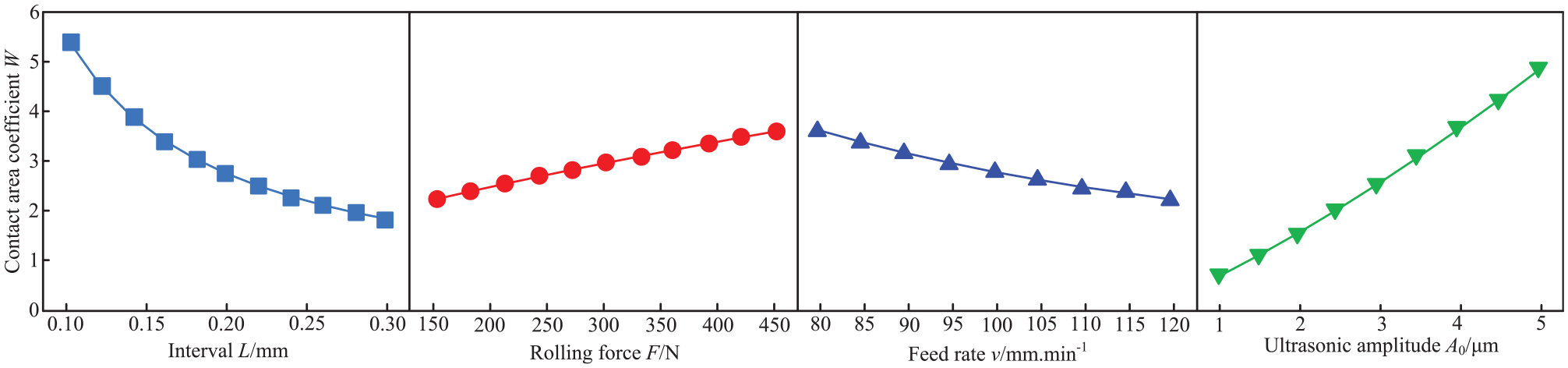
Effect of process parameters on contact area coefficient.
As shown in Figure 38, the residual compressive stress slightly decreased with feed rate, and the stability was receded in both directions. With an increase in the interval, the residual compressive stress significantly decreased, and the stability in the axial direction was higher than that in the circumferential direction.
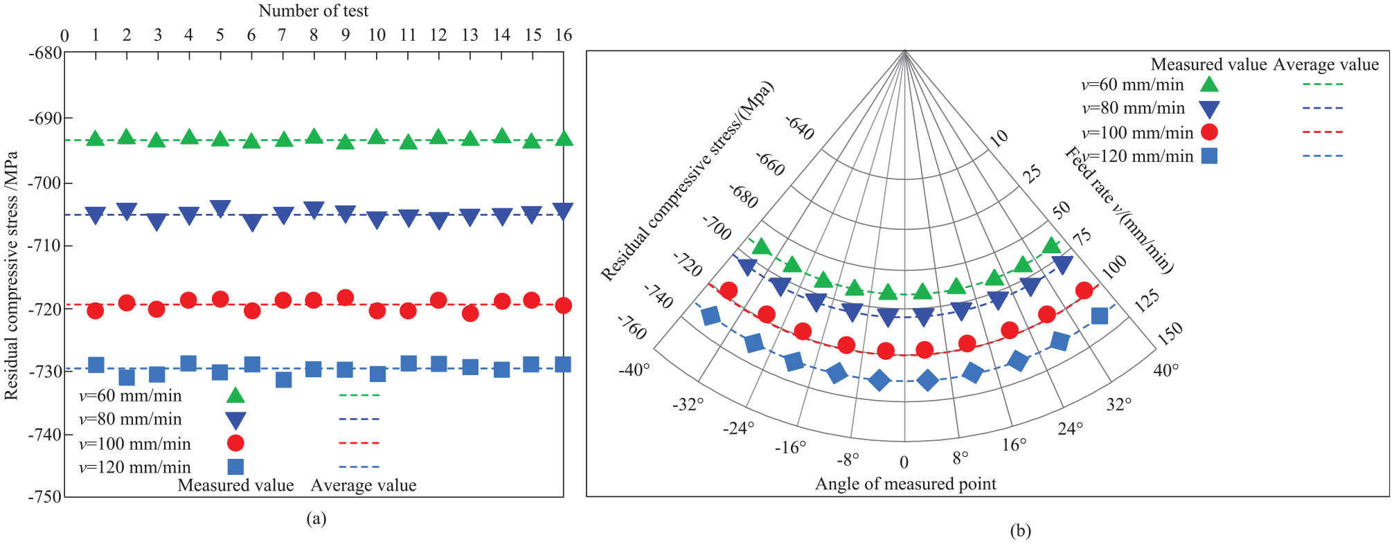
Effect of feed rate on stability of residual stress: (a) axial direction and (b) circumference.
Combining with the principle of involute gear meshing and the rotary machining mode, Gao et al. 144 developed the double-roller gear longitudinal torsional compound ultrasonic rolling device. It can effectively solve the problems, such as low strengthening efficiency and small action area.
According to the description, the investigation on the ultrasonic reinforcement of gear was relative limited. In the previous studies, the surface roughness, hardness, residual stress, and tooth profile deviation of the tooth surface were greatly improved under the ultrasonic deep rolling. However, a few studies were conducted on the nanolayer generation after ultrasonic deep rolling because the involute of the tooth surface was quite complex. In addition, due to the limited conditions, the processing efficiency was lower. Thus, the number of researches report on the application of ultrasonic deep rolling machining to gear strengthening. Therefore, it is necessary to further develop and analyze the ultrasonic deep rolling technology in gear manufacturing with enhanced fatigue resistance.
Development of ultrasonic machining in gear fatigue resistance manufacturing
In ultrasonic machining, the basic vibration modes comprise longitudinal vibration, torsional vibration, and bending vibration. With the development of ultrasonic machining, the composite vibration mode has been widely used in many fields. In ultrasonic gear machining, composite vibration mode will occur, including longitudinal-bending, longitudinal radial, and radial-bending vibrations. Therefore, the related design theory, calculation analysis, and vibration characteristics are more complicated than those of a single vibration mode.145–148 At the same time, the effect of ultrasonic gear machining needs to be characterized with reasonable parameters. However, as it was shown in Figure 4, surface integrity depends on many parameters, so it is necessary to select effective parameters for the evaluation of surface integrity. In addition, in order to produce high-performance gears with high fatigue resistance, one needs to investigate the fatigue failure mechanism of gear surface microstructure, crack propagation patterns, notch sensitivity, and size effect under ultrasonic vibration. Moreover, the genetic evolution of the surface integrity under the coupled effect of multiple energy fields should be studied to obtain the quantitative relationship between the surface integrity and processing conditions. This will provide a novel precise and efficient processing technology of gear manufacture.
Theoretical basis
In ultrasonic gear machining, the machined gear is treated not only as a workpiece, but also the load for the ultrasonic vibration system. The gear structure does not depend on the frequency of ultrasonic vibration system, but varies by its application. However, in practical applications, it is difficult to keep the resonant frequency of the processed gear within the required range because the frequency adjustment range of ultrasonic vibration system is limited. In view of this, the ultrasonic vibration system composed of gear and horn is relatively complex. It is necessary to explore a reliable design theory for the vibration system. When designing an ultrasonic honing vibration system with a large load, Zhao et al.149,150 adopted the local resonance theory to design the system and made the system well resonant by tuning the frequency of ultrasonic generator. When conducting the ultrasonic lapping test, Wu et al. 151 integrated the tool and horn into a design, where the tool was simplified to a small round cone. According to the longitudinal vibration wave equation of a variable cross-section, continuity conditions of stress and velocity, and boundary conditions, the frequency equation of the combination was established, obtaining the relationship between the size variation of small bevel gear and the resonant frequency. Therefore, the local resonance theory was suitable for the ultrasonic vibration system.
Based on the Mindlin plate theory, She et al.152,153 simplified the gear to a thick circular plate with a reference circle diameter. The dynamic model of ultrasonic honing gear was established according to the coupled relationship in the vibration system. The theoretical results were a good agreement with the FEM simulation. Liang et al. 154 designed the longitudinal resonant vibration system for ultrasonic honing gear based on the non-resonant theory. According to the variable cross-section wave equation of longitudinal vibration, Zhang 155 realized the gear vibration system designation, in which the gear behavior was adapted to bending vibration.
However, till date, the vibration system designation was based on the one-dimensional vibration theory, and the Poisson effect was not considered in the designation. 148 For the ultrasonic gear machining system, the vibration system was no longer a slender rod, and the one-dimensional vibration theory was not suitable for the designation. Alternatively, the Ritz 3D vibration numerical method can be applied to the vibration system. In the early stage of ultrasonic gear processing, the gear is simplified according to the thin plate theory. In fact, the gear thickness-to-diameter ratio in processing mainly corresponded to medium-thick plates. Therefore, the medium-thick plate should be employed to establish the vibration model.
Ultrasonic vibration system
The stability of ultrasonic vibration system and fatigue resistance of gears plays a key role in the gear manufacturing. In ultrasonic gear machining, the processed gear acts as a large load for the vibration system, it must be considered in the designation. Consequently, the gear and horn are regarded as a whole body to establish the corresponding vibration model, and the structure of ultrasonic gear machining is shown in Figure 39.

Vibration system design of gear ultrasonic vibration-assisted machining.
The available ultrasonic vibration systems have been designed with a tool or workpiece unilateral consideration. Considering the two-dimensional or multi-dimensional ultrasonic machining technology development, the new requirements are proposed for the designation of vibration system. Whether the tool or workpiece acting as a large load were designed according to the local resonance theory resonance within a certain frequency range or not will significantly affect the stability and effect of ultrasonic machining.156,157 In addition, few studies were carried on the effects of ultrasonic vibration amplitude, frequency and processing parameters on the stability, as well as stability criteria for the whole system. Therefore, it is necessary to develop a reasonable mathematical model to realize the combination between ultrasonic parameters and machining parameters, and assess the stability of the vibration system. Based on the local resonance theory and regeneration effect, Zhang et al.158–160 established the dynamic models of feed direction, vertical feed direction, elliptical, and torsional ultrasonic vibration-assisted milling, respectively. The dynamic models in different directions can be unified by the following differential equation:

where
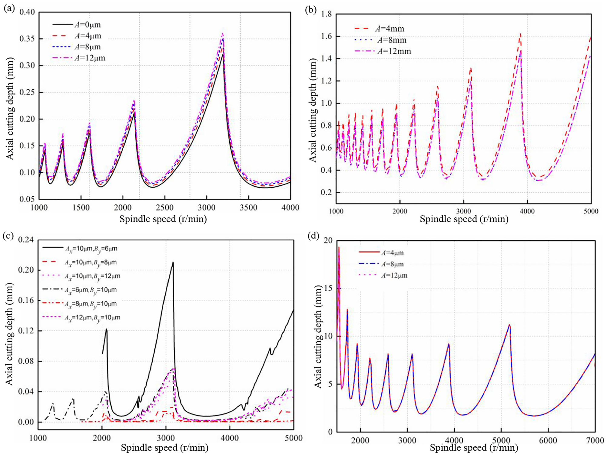
Stability prediction diagram of ultrasonic vibration assisted milling in different directions: (a) feed direction, (b) vertical feed direction, (c) elliptical vibration, and (d) torsional vibration.
Whether the surface quality generated by ultrasonic machining is stable or not, and whether the surface stress and texture formed by the combination of processing parameters and ultrasonic parameters is controlled or not mainly depends on the cutting stability of the composite system of ultrasonic vibration system and cutting system. In the above stability study, the structural modal coupling effect was ignored, while in the ultrasonic machining of gears, the structural coupling effect does exist, and its effect on the stability needs to be further studied. For the complex ultrasonic vibration system, the effect of factors on the stability gets more complex, making it difficult to study the stability. However, the stability of the vibration system plays an important role in the surface integrity. Consequently, the complex stability model of ultrasonic vibration system, the limiting cutting condition, and the stability criterion are of great significance to the development of ultrasonic gear machining.
Characterization of surface integrity parameters
In the ultrasonic gear machining, some research has been carried out, and the processing is mainly focused on the designation of full-resonance vibration system, cutting force, surface roughness, machining efficiency, tooth surface accuracy, material removal mechanism, and surface morphology under a single vibration model. However, a few studies were carried out on the characterization of surface integrity parameters. A larger number of parameters used for evaluating the gear surface integrity, makes it difficult to assess the effect of surface integrity parameters (surface micro-morphology, residual stress, micro-hardness, etc.) on fatigue resistance via reasonable parameters. At present, most studies on fatigue resistance are focused the residual stresses, work hardening, and surface micro-morphology. Zhao, 161 He and Deng, 162 Novovic et al., 163 Deng et al., 164 and Amarnath and Lee 165 reported that the determination of fatigue resistance cannot be attributed to a single surface integrity parameter, but should comprehensively consider the coupling effect of the surface geometry and surface metamorphic layer of many major surface integrity characteristics. Figure 41 presents the conceptual architecture of the surface integrity model. 166

Surface integrity model’s structural system.
The surface integrity model can be considered as a framework composed of the surface integrity feature domain and the surface integrity process condition domain. The former is composed of the characteristic parameters and the interactions between the feature quantities. The surface integrity process condition domain is composed of the choice of various process schemes and their relationships. Different processing schemes, selection of cutting parameters, etc. will directly determine the surface integrity characteristic parameters. The higher the requirements for the values of surface integrity characteristic parameters, the better the control of the selected process conditions. Simultaneously, the surface integrity characteristic parameter will also directly affect the fatigue life and service performance. The architecture of the conceptual model of surface integrity implies that the fatigue resistance can be eventually realized by controlling the processing conditions and the surface integrity characteristics.
In ultrasonic gear machining, the lower cutting force, lower temperature, cavitation effect, and impact effect will inevitably influence on the material strain-rate strengthening, thermal softening effects, and processing effect. The results of multiple effects coupled on the surface layer structure and stress state need to be further studied. As shown in Figure 42, the surface integrity structure obtained via the quantitative correlation between the gear surface integrity parameters and the fatigue failure needs to be created by the processing means and the configuration of processing parameters. In the calculation of contact stress and fatigue strength under micro-topography, Tang et al.167,168 adopted the fast Fourier transformation (FFT) reconstruction method to randomly simulate a large number of micro-topography samples, and obtained the calculation formulas for the micromorphological characterization parameters.

Quantitative correlation of gear surface integrity and fatigue failure.
The ellipsoidal micro-convex elasto-plastic contact model proposed by Ding et al. 169 made it possible to accurately solve the elasto-plastic contact problem of rough tooth surfaces. The average contact pressure and contact zone width variation during the meshing process of gear was obtained using the measured micro-topography data of the gear surface and the elasto-plastic contact model.
Based on the extended FEM, a two-dimensional stress field calculation program for cracked bodies was written in Fortran. The gears were employed to study the influence of initial crack length, direction, position, geometric parameters, and rotational speed on the path of crack propagation. The contact pressure field of the subsurface layer was calculated by randomly distributing the contact pressure in samples, and the average Mises stress of the subsurface layer was also determined. Based on the local stress-strain method and the Manson-Coffin formula, the crack initiation life was calculated, and the effect of micro-morphological parameters on crack initiation life under different meshing curvature radii was investigated. 170 Within the fracture mechanics framework, the effect of micro-morphological parameters on the crack propagation path and rate was obtained on the basis of the random distribution of contact pressure. These studies provided a theoretical basis for the fatigue resistance manufacturing mechanism with enhanced fatigue resistance.
The mechanism of ultrasonic parameters’ effect on the surface integrity performance of gears needs to be further studied. How to select appropriate machining parameters to achieve gear surface micro-morphology controllability with high fatigue resistance is topical from theoretical and practical engineering standpoints. Besides, the interrelations between the stress-strain state, structural state, surface microstructure, and fatigue performance of the processed surface under ultrasonic vibration conditions have to be clarified yet. Taking advantage of multi-dimensional ultrasonic processing benefits, compressive multi-dimensional ultrasonic gear machining is expected to have the required positive effect on the stability of complex vibration systems, surface residual stresses, surface microstructures, and fatigue resistance characteristics.
Thus, the multi-dimensional ultrasonic vibration combined with the conventional processing of gears can realize the active control processing of high-precision, high-efficiency, and fatigue-resistant gears for high-speed trains, new energy vehicles, and aerospace applications. At present, the industrial implementation of multi-dimensional ultrasonic vibration and gear composite machining is quite problematic, due to the lack of studies of complex systems composed of non-resonant gears and multi-dimensional ultrasonic resonant subsystems, as well as a low stability of such system. However, considering the lucrative characteristics and multiple advantages of ultrasonic machining, the ultrasonic and gear surface strengthening technologies can be effectively combined to ensure the ultrasonic compound machining of gear surface.
Prediction of gear fatigue strength, durability, and surface integrity evolution in metamorphic layers of gears after ultrasonic composite machining gears should take into account the micro-morphology and residual stresses generated in the processed surfaces under coupled multi-energy fields. Besides, such issues as completeness and the quantitative relationship between surface metamorphic layers are vital for developing a novel, actively controllable, reliable, precise, and efficient processing method for manufacturing of gears with enhanced fatigue resistance and durability, ensuring their high efficiency, quality, and reliability.
Conclusions and outlook
The above survey of available literary data revealed the limitations of ultrasonic vibration-assisted gear machining techniques and possible directions of their further development. Specifically, the following issues need to be urgently resolved.
The ultrasonic vibration systems of gear machining are restrained by the machine tool dimensions, gear shape and index, and the gear material limitations. It is necessary to design the complex vibration system of non-uniform materials and asymmetric hybrid structures.
The superimposition of one- and multi-dimensional ultrasonic vibrations in the ultrasonic gear machining need to be explored in order to obtain the optimal vibration mode. The corresponding vibration characteristics should be investigated to identify the mechanism of gear surface formation under one- and multi-dimensional vibrations.
The dynamic force effect under high-frequency vibration on the material deformation stress field, the temperature field in the processing area, the micro-mechanism of changes in crystals and grain boundaries, and the formation of nanolayers during high-speed impact of the material should be explored. This will make it possible to obtain the coupling relationship between the processing parameters and various effects, such as high-frequency impact, cavitation, temperature gradient, high strain rate, thermal softening, etc. In addition, the coupled relationship effect on the surface integrity need to be further explored.
It is necessary to establish the correlation between the surface integrity parameters of gears and ultrasonic parameters under the action of ultrasonic energy fields. Based on the surface integrity parameters, the processing parameters should be reasonably selected to provide optimization of the ultrasonic vibration-assisted gear machining with quantitative guidance from the surface integrity parameters to achieve the controllable gear manufacturing.
Footnotes
Acknowledgements
The authors would like to acknowledge the National Natural Science Foundation of China and the Key R&D and Promotion Program (Science and Technology) in Henan Province, China, and PhD Research Start-up Fund Project of Pingdingshan University of China.
Handling Editor: Chenhui Liang
Declaration of conflicting interests
The author(s) declared no potential conflicts of interest with respect to the research, authorship, and/or publication of this article.
Funding
The author(s) disclosed receipt of the following financial support for the research, authorship, and/or publication of this article: This work was financially supported by the National Natural Science Foundation of China (Nos. U1604255 and 51905157), the Key R&D and Promotion Program (Science and Technology) in Henan Province, China (No. 20202102210266), and PhD Research Start-up Fund Project of Pingdingshan University of China (No.PXY-BSQD-2022001).