
Abstract
A connectivity criterion based on the analysis of the stress intensity factor for the double cracks and inclusion was developed to study the residual life of large modulus crack. Applying the moving load, the finite element model in FRANC3D was proposed to study the variation law of the spacing ratio
Introduction
The Three Gorges vertical shiplift adopts rack-and-pinion climbing type. Its driving gear and rack modulus is up to 62.667 mm. The rack is G35CrNiMo6-6. After quenching and tempering, the surface of the rack is quenched by induction quenching. On one hand, due to the scale, there are few engineering application cases, mature design theory, and norms in terms of the large modulus rack. The surface cracks and inclusion inevitably appear after rack machining. On the other hand, the safety factor methods of contact strength and bending strength of tooth roots are still applied to check the design of rack in engineering, and the Miner fatigue cumulative damage theory is used to estimate the fatigue life of rack. This method fails to guarantee the accurate results. Therefore, it is essential to study the fatigue crack growth of large modulus rack.
In recent years, the fatigue crack propagation and fatigue life in medium and small gear have been studied with various methods, including contact stress method, power density method, and the establishment of particle filter model.1–3 For multiple crack propagation, the double crack growth is studied by extended finite element method.4,5 Also, the interference effect of the double crack was investigated experimentally. 6 Based on the peridynamics theory, an analysis of the collinear double cracks containing the initial defect was conducted. 7 For the coalescing of the multiple cracks, the experimental and numerical investigations are utilized in studying the semielliptical crack propagation.8–10
Regarding the research on fatigue crack propagation characteristics of gear/crack heat treatment, the effect of quenching on crack growth rate of metal materials was investigated.11–13 The residual stress distribution on the crack propagation of the gear root was analyzed on the basis of the electromagnetic-thermal-metallic-mechanical coupled numerical model. 14 In addition, the variations of hardness and residual stress introduced by carburizing and quenching processes have remarkable effects on the rolling contact fatigue for gear meshing. 15
However, the researches of the gear/rack crack propagation involved in the large modulus, as well as the initial cracks and inclusions, have not been found. Besides, few researches have been conducted about the influence of heat treatment on multiple cracks/inclusions propagation.
By applying moving load on the model in FRANC3D and studying the possible crack distribution rules on the large modulus rack, the interference effects between the double cracks and inclusion were analyzed quantitatively. Subsequently, a connectivity criterion was proposed to prospect the residual fatigue life of the large modulus rack.
Threshold of double cracks propagation with single inclusion
Cracks propagation model
To precisely simulate the mesh of gear/crack in working condition, a moving load method is introduced. In Figure 1, the rack is meshed with the pinion of the drive pinion bracket on the shiplift. Figure 1 signifies that each tooth surface of the load is discretized into 15 loading regions, consisting of 6 double teeth-meshing regions, 3 single teeth-meshing regions, and 6 double teeth-meshing regions, arranging from the top to the root of the tooth. The load of 15 loading regions of the rack can be computed by the gear meshing principle. 16 The boundary size of the rack model is the multiple of rack modulus. The width of rack is 800 mm, and the tooth height is 141 mm. The fatigue crack propagation analysis processes in FRANC3D are as follows:
The finite element simulation model for the large modulus crack containing the initial double cracks and the inclusion is proposed (Figure 1).
The stress of the finite simulation model for the large modulus crack containing the initial double cracks and the inclusion is calculated by finite element theory.
Reading the stress analysis results, compute stress intensity factor (SIF) of the front points of the cracks, analyze crack propagation, update crack front position, and re-mesh the finite element model in FRANC3D.
Repeat steps 1–3, until the end of the fatigue crack propagation.

Simulation model of large modulus crack.
According to the results of crack and inclusion detection of large modulus rack, it is assumed that the inclusion on the surface is a hemispherical cavity with a diameter of

Defects of large modulus rack: (a) inclusions and (b) cracks.
Spacing ratio threshold
Table 1 signifies the variable law of SIF in the fatigue crack propagation of large modulus crack with the initial spacing between inclusion and double cracks
Variable law of SIF in the fatigue crack propagation of large modulus crack.

SIF: stress intensity factor.
As shown in Table 1, the SIF at the left and right ends of the initial crack are equal at the beginning of propagation, indicating no interference in the propagations of the double cracks and inclusion. With the increase in the propagation step, the SIF of the right end of the left crack is greater than that of the left crack, and the SIF of the left end of the right crack is greater than that of the right crack. This indicates that more intense propagation begins to occur in the ends of double cracks near inclusion. Thus, the increasing propagation step results in the smaller initial spacing between double cracks and inclusion, and the greater difference of SIF for the two ends of the same crack (left crack or right crack of inclusion).
For the assessment on the SIF reinforcement effect, it is useful to determine the SIF amplification coefficient


Different initial spacing: relationship between
On the basis of Figure 3 and variation of derivative function of equation (1), some critical points can be seen: when
Initial spacing threshold
Fatigue load cycle number of large modulus rack is calculated when the double cracks and inclusion propagate to the spacing ratio threshold, with the various initial spacing
where

where


where

Rack hardness distribution.
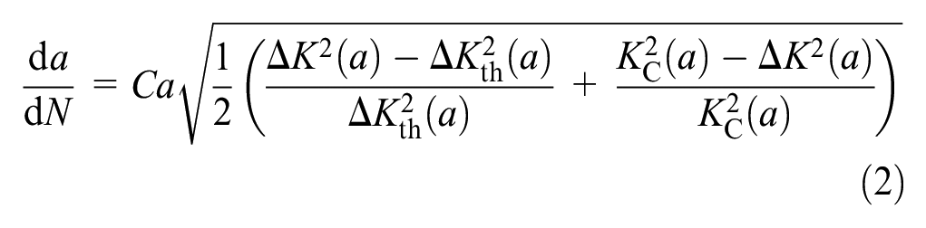
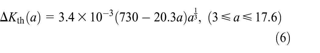
The crack growth threshold of the large modulus rack after quenching is arranged in the form 22
Next, the application of the integral operator for equation (2) leads to the following equation

Due to the complex structure of integral formula, the solution of equation (7) is completed by the compound trapezoid formula.
In Figure 5, the variable law between the number of fatigue load cycles

Fatigue load cycle number of double cracks and inclusion.
The design life of the Three Gorges shiplift is
Connectivity criterion of double cracks with single inclusion
Initial equivalent crack length
For circular mode I crack on the surface of a finite body, the general expression of SIF is given by 23

where

where

Semicircular crack.
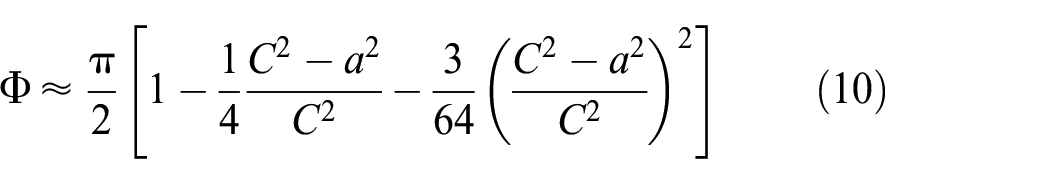
Overall, the series expansion of
Based on the results in various initial spacing, the relationship of

From equation (11),

On the basis of equations (8)–(12), the

Now, equivalent initial crack length after fusion of double cracks and inclusion is obtained according to
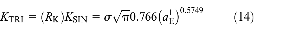
According to equations (13) and (14), the depth of a single crack after equating based on the amplification effect of SIF is defined as

Therefore, the length of a single crack after equating based on the amplification effect of SIF is defined as

Fatigue load cycle correction coefficient
The double cracks and inclusion will eventually fuse into a single crack with length of


Combination and propagation of double cracks and inclusion: (a) double cracks and inclusion merge into single crack

The final equivalent crack length corrected by the fatigue load cycle correction coefficient is defined as

where
Next, the number of fatigue load cycles required for a propagation from

For double cracks and inclusion, the number of fatigue load cycles required for a single crack with a final fusion growth of

Finally, the other form of

If

When
Correction coefficient of fatigue load cyclic number for

Connectivity criterion
The calculating procedure of the connectivity criterion proposed in this article is shown as follows:
Based on the detection results for the large modulus rack, the spacing ratio between double cracks and inclusion
The SIF amplification coefficient
Based on equation (23), the fatigue load cycle correction coefficient
Based on the initial spacing of the double cracks and inclusion, the final equivalent crack depth corrected by the fatigue load cycle correction coefficient
Fatigue life of surface-quenched rack
Maximum allowable crack length
For a single crack length
As shown in Figure 8,

where

Relationship between
Forecast of fatigue life
The procedure of the forecast of fatigue propagation life is shown as follows:
In accordance with the connectivity criterion (in 3.3), the double cracks and inclusion are combined into an equivalent single crack.
Based on the equivalent single crack length, the absolute safety of the large modulus rack is determined.
After comparison between the equivalent single crack length and the maximum allowable crack length
Calculating the equivalent crack growth in the residual service life helps to judge whether the ultimate crack growth reaches the maximum allowable crack length in the residual service life or not.
For the Three Gorges Vertical shiplift servicing for
However, the whole service life of the large modulus rack in the shiplift is also analyzed by Miner fatigue cumulative damage theory that is a conventional method. The equivalent load of the rack
where
Conclusion
The key observations are summarized as follows:
The variation law of the SIF amplification coefficient
In the case that the initial crack size
In order to obtain a single crack equivalent to the double cracks and the inclusion, the connectivity criterion is proposed. At first, the initial equivalent crack length is calculated with the SIF amplification coefficient. Subsequently, in accordance with the equivalent principle of the number of fatigue load cycles, the final equivalent crack length is obtained through the use of correction coefficient of fatigue load cyclic number
For the Three Gorges Vertical shiplift, in the case that the initial crack size
Footnotes
Handling Editor: James Baldwin
Declaration of conflicting interests
The author(s) declared no potential conflicts of interest with respect to the research, authorship, and/or publication of this article.
Funding
The author(s) disclosed receipt of the following financial support for the research, authorship, and/or publication of this article: The work presented in this article was supported by the National Key R & D Program of China (No. 2016YFC0402002), and the authors gratefully acknowledge this support.