
Abstract
Owing to the limited accuracy and measurement uncertainty of the instruments installed in gas pipeline systems, it is impossible to completely avoid transmission loss during transportation of natural gas. This study established an uncertainty model for the measurement system determining the complex flow rates of trunk gas pipelines, analyzed the uncertainty calculation methods of different metering systems, and developed a calculation method for determining the theoretical transmission loss. Application showed that the theoretical transmission loss serves not only as an early warning regarding a transmission loss, but also as a guide to the pipeline enterprise for determining the transmission loss assessment index. If the actual transmission loss rate is smaller than the theoretical transmission loss rate during the calculation cycle, it means that the pipeline metering system is working normally. Otherwise, it is necessary to immediately investigate the reason behind the transmission loss and implement corresponding measures.
Introduction
A generic definition of transmission loss of gas is the difference between metered gas receipts and metered gas deliveries to end-use customers; in other words, the volumetric difference between the gas injected into a pipeline system and the gas measured at customers’ meters. 1 Transmission loss is essential in the accounting, management, security, and physical balancing of natural gas networks, as well as for accurate consumption billing. Nevertheless, owing to a certain accuracy level and measurement uncertainty of the installed instruments, it is impossible to completely avoid pipeline transmission loss. The sources for actual transmission loss in natural gas pipelines include the measurement error of the measuring system, pipeline leakage, theft, and other factors; 2 the main sources can be ascribed to errors in measuring the natural gas entering and leaving the network. 3 In an investigation conducted by the Gas Research Institute (GRI), the largest contributors to unaccounted-for (UAF, equivalent to transmission loss) gas flow were measurement errors (81.64% of UAF gas flow), with the remainder split between leakage (8.85%), theft (6.54%), and accounting (2.97%). 4 Even though the transmission loss of gas in pipeline has been investigated many times,5–7 few studies have been conducted regarding the theoretical transmission loss and the related uncertainty estimation. Theoretical transmission loss in trunk gas pipelines means that all measuring devices (meters) in the system are in the ideal operating condition (the design, manufacturing, selection, installation, use, maintenance, and calibration of the instruments fully meet the requirements of relevant standards), with possible measurement errors due to flow measurement uncertainty.
For natural gas pipeline enterprises, the magnitude of the transmission loss is, to some extent, directly related to the economic status of these enterprises and is an important technical and economic index to evaluate production costs and production levels. Taking the joint-stock gas pipeline of China National Petroleum Corporation (CNPC) as an example, in 2012, its total output was approximately 24.2 billion cubic meters, while the amount of gas losses reached approximately 60 million cubic meters. 8 This brought about significant economic losses to the enterprise. Therefore, it is necessary to investigate gas losses during transportation in trunk gas pipelines.
The premise of transmission loss management is that reasonable transmission loss assessment indicators are known within the calculation cycle. However, owing to the different structures of natural gas pipelines and internal management policies of pipeline enterprises, there are no standard transmission loss assessment indicators in the industry at present; the transmission loss assessment indicators formulated by one enterprise are not suitable for all natural gas pipelines. Therefore, based on the error transfer and synthesis theory, analyzing the theoretical transmission loss in trunk gas pipelines can not only provide guidance for enterprises to develop transmission loss assessment indicators, but also provide early warning regarding transmission loss. Hence, in this study, an uncertainty model for a measurement system determining the complex flow rates of a trunk gas pipeline was established. We analyzed the uncertainty calculation methods of different metering systems based on the error theory and obtained the measurement uncertainty of the inlet and outlet ends of a trunk gas pipeline; a calculation method for determining the theoretical transmission loss was developed and the influencing factors were analyzed.
Establishment of measurement system model for trunk gas pipeline
A trunk gas pipeline system generally considers the gas station as a node, along which there are several inlet and outlet gas metering points for trade handover, vent gas, and self-consumption gas metering. Overall, a trunk gas pipeline can be regarded as consisting of two parts: an inlet end and an outlet end,
9
as shown in Figure 1. The inlet end is composed of

Simplified diagram of a trunk gas pipeline metering system.
Calculation method for theoretical transmission loss in trunk gas pipeline
A natural gas measuring system is a complex measurement chain consisting of different devices for the measurement, elaboration, correction, updating, and transmission of gas flow and date, 10 as shown in Figure 2. A volumetric measuring device for natural gas comprises several devices: a primary flow device, pressure transmitter, temperature transmitter, gas chromatograph, and flow computer.
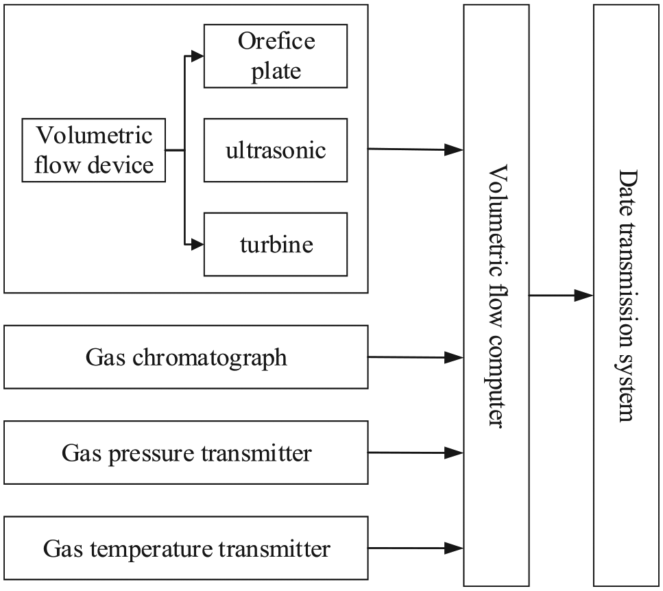
Flowchart of a volumetric natural gas measurement chain.
To analyze the theoretical transmission loss in the whole trunk gas pipeline system, suppose that the measurement instruments in the branch measuring system are independent of each other and the pipeline operation parameters are measured independently by the related instruments, and then, the theoretical transmission loss can be obtained by the following three steps: the first step is to determine the combined uncertainty of a single measuring system; the second step is to calculate the combined uncertainty of the parallel flow measuring system; and the third step is to obtain the combined uncertainty of the inlet and outlet ends. Thus, the theoretical transmission loss in the trunk gas pipeline system can be obtained.
Combined uncertainty of a single measuring system
There are many types of metering instruments in trunk gas pipeline systems, including standard orifice, turbine, and ultrasonic flowmeters. The measured value of the flowmeter only represents the instantaneous gas flow rate of the measured gas under operating conditions, which needs to be converted into the flow rate value under standard reference conditions according to equation (1) during trade handover. 11 In order to be distinguished from the total rate Q, the flow rate here is represented by lowercase q

where
It can be seen from the above equation that the flow rate under standard conditions is related to the pressure, temperature, and compression factor. Therefore, the uncertainty of the metering system is related to the uncertainty of the pressure, temperature, and compression factor.
Uncertainty of measurement system comprising velocity flowmeter
The ultrasonic and turbine flowmeters used for gas flow measurement in trunk gas transmission pipeline systems are velocity flowmeters. According to the rule of uncertainty propagation, 12 the combined standard uncertainty of velocity flowmeters under the standard reference condition calibrated during real flow can be calculated according to equation (2)13,14

where
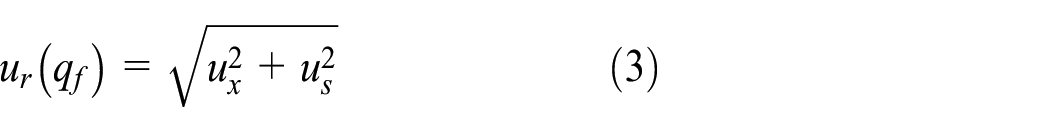
1. Relative standard uncertainty of flow measurement
The relative standard uncertainty of flowmeter measurements of natural gas under operating conditions is calculated as follows
2. Relative standard uncertainty of pressure measurement
The relative standard uncertainty of pressure measurements of natural gas under operating conditions is calculated as follows

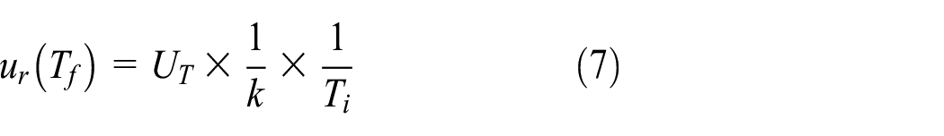
3. Relative standard uncertainty of temperature measurement
The relative standard uncertainty of temperature measurements of natural gas under operating conditions is calculated as follows

If the verification or calibration certificate of the temperature transmitter has only expanded uncertainty and no accuracy class, and the expanded uncertainty unit is milliamperes, as shown in equation (6), the milliamperes needs to be converted to degree Celsius first according to the relationship between temperature (the range is

When the unit of expanded uncertainty is degree Celsius, the relative standard uncertainty is calculated as follows
Equations (5)–(7) are all methods for calculating the relative uncertainty of temperature; the calculation methods are different according to the known conditions.
4. Relative standard uncertainty of compression factor calculation
If the standard of ISO 12213-2:2006 15 is used to calculate the compression factor, the relative standard uncertainty of compression factor calculations under operating conditions is 0.05%.
Under the standard reference condition, the relative standard uncertainty of the compression factor is related to the analysis method of natural gas composition and standard gas. If it is carried out according to China’s standard (GB/T 13610-2014) 16 and a secondary standard gas is used, the relative standard uncertainty of compression factor is 0.05%.
In equations (3)–(7),
Uncertainty of measurement system comprising standard orifice flowmeter
The equation for the combined standard uncertainty of the measurement system with a standard orifice flowmeter is given as follows 17

where
1. Relative standard uncertainty of the discharge coefficient
The relative standard uncertainty of the discharge coefficient
17
is determined using
When
When
When
When
When
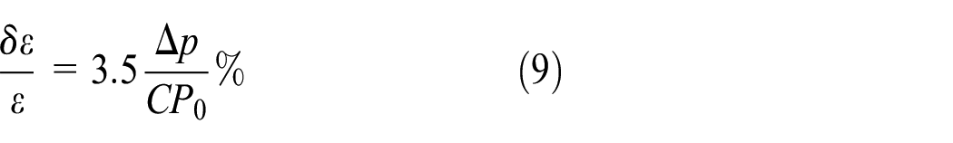
2. Relative standard uncertainty of the expansibility factor 17
3. Relative standard uncertainty of differential pressure measurement
When the confidence level is 95%, the uncertainty of the differential pressure measurement is calculated using the following equation12,18

4. Relative standard uncertainty of temperature measurement

5. Relative standard uncertainty of pressure measurement

6. Relative standard uncertainties of compression factor measurement
If the standard of ISO 12213-2:2006 15 is used to calculate the compression factor, the relative standard uncertainty of compression factor calculations under operating conditions is 0.05%. If it is carried out according to the standard of AGA NX-19, then the relative standard uncertainty is 0.25%.
In the above equations,
Combined uncertainty of parallel flow measuring system
When the volume of a branch is large, owing to the high price of the high-pressure, large-flow measuring instruments and their limitations in terms of the flow measurement range, it is common to use multiple flow metering systems in parallel to measure the gas flow of a metering branch. Suppose that one of the gas inlet branches is connected with

Combined uncertainty of flow measurement at inlet and outlet ends
A trunk gas pipeline system can be regarded as consisting of two parts: an inlet end and an outlet end. The inlet end is composed of

Similarly, the total combined uncertainty of measurements at the gas outlet end can be obtained as follows

Theoretical transmission loss in trunk gas pipeline systems
Reasons for actual transmission losses in natural gas pipelines include measurement errors of the metering system, pipeline leakage, and other factors, among which the measurement error of the metering instruments is the main cause of transmission losses. Therefore, according to the flow measurement uncertainty of trunk gas pipelines, the possible measurement deviation caused by the uncertainty of measurements at the inlet and outlet ends can be obtained, which is defined as the theoretical transmission loss in the trunk gas pipeline.
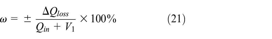
The theoretical transmission loss in trunk gas pipeline can be calculated according to the following equations


The theoretical transmission loss rate in trunk gas pipelines can be expressed as follows

where
It can be seen from the above equations that the theoretical transmission loss is related not only to the uncertainty of the metering devices, but also to the pipeline structure and operating parameters; therefore, the theoretical transmission loss has different values in different calculation cycles. The flowchart for theoretical loss calculation is shown in Figure 3.

The flowchart of theoretical loss calculation.
Application of theoretical transmission loss
According to industry standards of China, the equations for calculating the actual transmission loss in natural gas pipeline are as follows 21

where
In equation (20),
In China, the pipeline gas inventory is calculated by equation (22)

The average pressure


where
According to the calculation results of the actual and theoretical transmission loss, the theoretical loss has the following uses:
1. The comparison between the actual and theoretical transmission loss can provide an early warning regarding transmission loss. If the actual transmission loss is smaller than the theoretical transmission loss in the calculation cycle, it means that the pipeline measurement system is working normally; if the actual loss is much larger than the theoretical loss, it is necessary to find out the reason immediately, conduct positioning analysis for determining the source of the transmission loss, and take corresponding measures to control and reduce the transmission loss.
In other words, rather than merely comparing the difference between the theoretical transmission loss and the actual loss, the two should be compared to provide an early warning regarding transmission loss. The actual transmission loss changes each month, but the theoretical loss may be concentrated around a certain value. The actual loss is within the acceptable range as long as it is less than the theoretical loss; this also indicates that the metering system is working normally.
2. If the pipeline gas volume does not change much, then the theoretical transmission loss will be concentrated around a certain value, which can provide guidance for enterprises to develop assessment indicators for the transmission loss. In addition, the transmission loss will be affected by many adverse flow patterns such as pulsating flow and external factors in actual situations. Therefore, enterprises can appropriately add certain values based on the theoretical loss according to the actual situation when formulating the assessment indicators for transmission loss.
Factor influencing theoretical transmission loss
Pipe structure
The theoretical transmission loss is related to the pipeline structure. Different pipe structures have different numbers of metering branches with different types of flow. These constitute the combined uncertainties of different pipeline systems and finally the theoretical transmission loss. Suppose that two pipes with the same total inlet and outlet gas volumes have
Types and models of metering devices
The theoretical transmission loss is related to the types and models of a metering device. There are many types of flowmeters commonly used in gas pipelines, such as ultrasonic, turbine, and orifice flowmeters. Different types or models of flowmeters have different accuracy classes, which make the uncertainties of a single metering system different; after error transmission and synthesis calculations, the final theoretical loss is also different. Suppose that the structure and branch flow of the two pipelines are the same, and the branch uncertainties are
Pipeline operation parameters
The theoretical transmission loss is related to the operating parameters of the pipeline. The operating parameters of pipelines include the pressure, temperature, and flow rates. Different pressures and temperatures result in different standard flow rates after conversion, and different flow rates will directly affect the theoretical transmission loss calculations.
Case analysis
The YJ pipeline, a trunk gas pipeline in China, has a total length of approximately 940 km, and its designed annual capacity is 30 × 108 N m3. The metering equipment of the trunk gas pipeline mainly comprises ultrasonic flowmeters and is supplemented by turbine flowmeters. There are 29 metering branches along the route, including 15 gas stations and one underground gas storage, as shown in Figure 4.
22
The standard uncertainty of various types of flow rates and instruments is shown in Table 1, and the monthly operating dates of gas transmission trunk lines in the first half of 2018 are given in Table 2. Here,
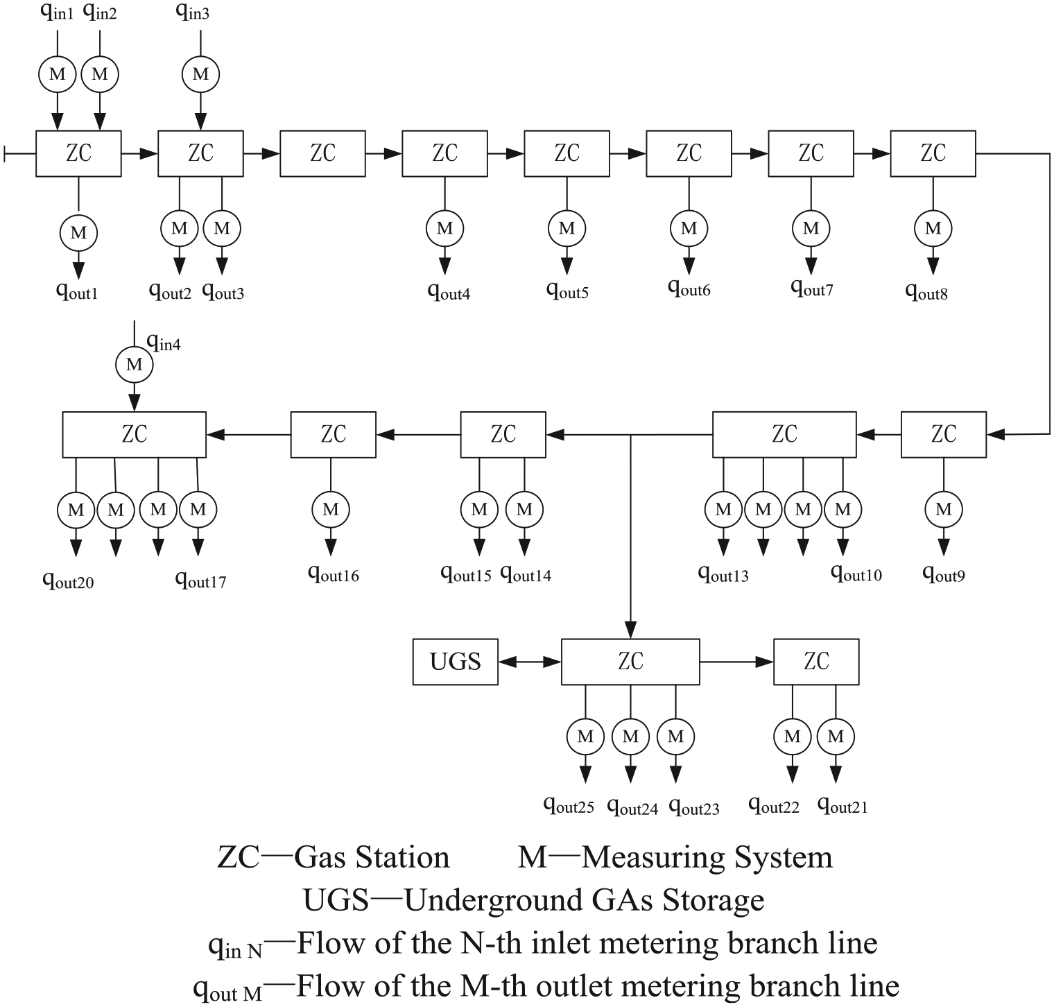
Structure diagram of trunk gas pipeline.
Standard uncertainty of various types of flowmeters and related instruments (%).

Monthly operating date of gas transmission trunk line in the first half year in 2018 (m3).

USGin and USGout, respectively, represent the gas production volume and gas injection volume of the underground gas storage.
Relevant data for actual transmission loss (m3).

Theoretical transmission loss rate of the trunk gas pipeline (±%).

It is evident from Table 4 that the theoretical transmission loss in the natural gas pipeline from January to June 2018 is concentrated at approximately 0.21%. (In fact, the calculation result of the theoretical transmission loss is ± value, and the absolute value is shown in the case analysis.) Therefore, pipeline enterprises can consider 0.21% as the transmission loss assessment index value for this pipeline under the premise that the pipeline transmission volume does not change much. In addition, 0.21% can also be used as the index value for early warnings regarding transmission loss.
Comparing Tables 3 and 4 shows that the actual transmission loss rate between January and March is much larger than the theoretical transmission loss rate. Therefore, it is necessary to find out the reason immediately, conduct a positioning analysis to determine the source of the transmission loss, and take corresponding measures to control and reduce the transmission loss.
Flowmeters provide their best metrological performance only in a restricted flow rate range (characteristic of the measurement principle). This range is between the transition flow rate
The operation flow rate in some measurement branches of the YJ pipeline is shown in Figure 5, the black lines represents the branch flow fluctuation curves qout, the blue lines and the red lines represent the upper limit

The operation flow rate in some measurement branches.
Conclusion
Based on the error theory, the theoretical transmission loss can be obtained according to the pipeline structure, operating parameters, and uncertainties of the measurement system. It means that under ideal conditions (the design, manufacturing, and installation of meters meet the requirements of relevant standards), the flow measurement deviations in gas transmission pipelines may be attributed to the accuracy of the meters and measurement uncertainties; these are related to the pipeline structure, operating parameters, and the types and models of the metering devices.
Theoretical transmission loss can be used as an early warning indicator regarding pipeline transmission loss. If the actual transmission loss rate is smaller than the theoretical transmission loss rate during the calculation cycle, it means that the pipeline metering system is working normally. Otherwise, it is necessary to find out the reason immediately, conduct positioning analysis to determine the source of the transmission loss, and take corresponding measures to control and reduce the transmission loss.
Under the premise that the amount of gas transported by the same pipeline does not change much, the theoretical transmission loss rate can provide guidance for pipeline enterprises to develop transmission loss assessment indicators.
Different pipelines have different theoretical transmission losses due to different pipeline structures, types and models of metering devices, and operating parameters.
Theoretical transmission loss can be defined as the deviation in flow measurement caused by measurement uncertainties under the assumption that the measurement instrument is in an ideal state. However, in an actual situation, this assumption is usually not valid. Therefore, enterprises should consider including an additional value when formulating the transmission error assessment index based on the theoretical transmission error. In future research, the influence of measurement uncertainty on the transmission loss in non-ideal conditions of measuring instruments will be investigated, and the magnitude of the additional uncertainty will be determined.
Footnotes
Handling Editor: James Baldwin
Declaration of conflicting interests
The author(s) declared no potential conflicts of interest with respect to the research, authorship, and/or publication of this article.
Funding
The author(s) received no financial support for the research, authorship, and/or publication of this article.