
Abstract
This article reports a numerical analysis of combined natural convection and non-gray gas radiation within a cylindrical enclosure, isothermally heated and cooled on various arc lengths of the sidewall. Three active zone locations are studied in this article. The first heating section extends quarter the perimeter of the cavity, the second spreads across one-half of the cylinder, and the third one is made of three-quarters of the sidewall. The participating media are considered as emissive, absorbent, and non-scattering. The radiative transfer equation is resolved using the Ray-Tracing method associated to the Statistical Narrow Band–correlated K model. The effect of heater size and its location on heat transfer, fluid flow, and entropy generation are presented and discussed in this work. The results show that the optimum heater size is obtained for three-quarters heated enclosure. It was also found that choosing a heat source centered at the top of the enclosure provides the best heat transfer performance.
Introduction
The second law of thermodynamic has attracted great attention for many researchers due to its interesting role in different industrial applications such as electronic cooling, storage thermal systems, heat exchangers, and also nuclear reactors. It is important to note that the enhancement of their performance and the improvement of energy efficiency depend strongly on the reduction of the entropy generation1–9 due to heat transfer, mass diffusion, fluid friction, and the thermodynamic irreversibility. 10 Varol et al. 11 analyzed entropy generation during conjugate natural convection in enclosures. They concluded that entropy production caused by heat transfer is more significant than that generated due to fluid flow irreversibility. Narayan et al. 12 performed a detailed procedure of minimizing entropy generation due to coupled heat and mass exchange processes. Using the entropy generation minimization techniques, Makhanlall et al. 13 succeeded in finding optimum optical thickness and tilt angle for gas filled solar collectors, thus minimizing heat losses. Hajji et al. 14 reported a numerical analysis of entropy generation attributed to natural convection and radiation within an inclined rectangular enclosure. They found that the minimum entropy generation due to volumetric radiation is achieved at aspect ratio equal to unity.
As we all know, natural convection is the subject of many research works owing to its presence in many engineering applications such as boilers, heat exchangers, and solar collectors. Thermal radiation also presents a significant effect in this wide range of industrial applications. It is worth mentioning, however, that most of the research studies dealing with coupled radiation and natural convection have only been interested in presenting the influence of surface radiation on the heat transfer process. Nevertheless, the volumetric radiation within participating gases should be taken into account for higher temperature range. Colomer et al. 15 investigated the radiation phenomenon and natural convection through transparent and participating media within a differentially heated three-dimensional (3D) cavity. They analyzed the effects of optical thickness and also Planck and Rayleigh numbers on heat flux. The coupling of free convection and gas radiation in a vertical cylinder is depicted by Mazgar et al., 16 with particular attention paid to the volumetric entropy generation due to thermal radiation. Ben Nejma and colleagues17,18 analyzed numerically entropy generation ascribed to radiative transfer within an emitting-absorbing and non-gray gas inside cylindrical and spherical enclosures, respectively. By using the Ray-Tracing method in association with the Statistical Narrow Band–correlated K (SNBcK) model, they demonstrated that the volumetric entropy generation caused by radiation heat transfer is the most developed for heating cases, whereas entropy generation due to wall radiation is the most developed in cooling configurations. Jarray et al. 19 studied radiative heat transfer inside a cylindrical annulus with isothermally heated and cooled horizontal walls. They showed that entropy generation is highly affected by wall and gas temperatures, and specifically the dominance between entropy generation attributed to gas and wall radiation depends primarily on the difference between wall and gas temperatures.
On the contrary, partial heating was introduced as a new heat transfer process in order to obtain higher energy efficiency with respect to exergy losses.20–25 Mazgar et al. 26 highlighted the effects of natural convection coupled to non-gray gas radiation between two vertical plates partially heated and made of two equal parts, alternately isotherm and insulated. They proved that attenuation of the radiative contribution between heating from the bottom and from the top is not as expected. Mirzaie and Lakzian 27 analyzed free convection two-dimensional (2D) flows in a horizontal annulus, presenting the effects of discrete heating zones on free heat transfer. They proposed the best disposition of discrete heat source ensuring the best heat transfer rate. Guestal et al. 28 performed a numerical analysis of natural convection heat transfer inside a horizontal cylindrical cavity filled with nanofluids. They obtained correlations for the mean Nusselt numbers to better mirror the heat transfer process through the enclosure.
Based on the literature, it can be remarked that cylindrical partial heating through various arc lengths of the sidewall does not receive enough attention, especially when natural convection is coupled to non-gray gas radiation. That is why the present study is devoted to analyze combined natural convection and non-gray gas radiation through a partially heated cylinder. The predictions of temperature and velocity fields are done through a numerical model, according to the great importance to the effect of the heater size and location on heat transfer. The computation of the mean Nusselt number and the average entropy generation, as well as the energy efficiency and exergy losses, are presented and discussed in this article.
Problem formulation
The physical problem under study and the boundary conditions are shown in Figure 1. It consists of a horizontal cylindrical enclosure of infinite length, with an angularly localized heat source. The heater size which is equivalent to a circular arc is limited by φ1 and φ2, and is centered at φ0. The heated and the cooled zones are kept at constant temperatures of Th and Tc, respectively. Three configurations of partial heating are considered. The first heating section (case 1) is spread across one-quarter of the circular wall; the second extends half the perimeter of the cavity (case 2), and the third (case 3) is made of three-quarters of the sidewall. The working fluid (overheated steam) is supposed to be Newtonian and in laminar flow with no-slip boundary conditions. It is considered as a perfect and temperature-dependent gas, where the physical properties are given by COMSOL Multiphysics. 14

Schematic diagram of the physical system.
According to the previous assumptions, the governing equations of the present study can be formulated as follows


Knowing that the application of the SNBcK approach 29 with the 4-point Gauss–Legendre quadrature permits to express the radiative source term as follows

Note also that the radiation intensity given in equation (5) is computed from the radiative transfer equation presented in equation (6) by using the Ray-Tracing method, 30 knowing that the participating media are considered as emissive, absorbent, and non-scattering


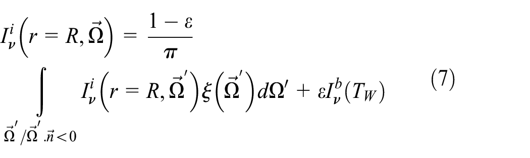
By taking into account the diffuse-reflection, the radiative boundary conditions are given by the following expression
On the contrary and as is often the case, entropy is generated due to the presence of thermodynamic irreversibility, mainly owing to heat transfer across finite temperature gradient. Accordingly, the expression of local entropy generation due to thermal conduction 31 is defined as

This is allowing us to formulate the expression of the global entropy generation due to heat conduction
Likewise, the local entropy generation due to volumetric radiation 32 is expressed as follows

Knowing that the spectral and directional radiative temperature is given by the following equation

Note that the spectral radiative entropy intensity 33 is calculated by the following expression

As a result, the global entropy generation due to volumetric radiation is given as follows

In parallel with this, the local radiative entropy generated at walls 34 is expressed as
The global radiative entropy generated by wall radiation is then calculated from the following expression

Keep in mind that the local convective and radiative Nusselt numbers at the heated section are established in order to characterize heat transfer between gas and walls. They are expressed, respectively, according to equations (16) and (17)


The mean conduction and radiation Nusselt numbers at the heated section are calculated for the purpose to achieve an overall vision of heat transfer through the enclosure. They are expressed as follows

where

The average distributions of temperature and velocity fields are computed in order to provide a global overview of fluid flow and heat transfer features. They are given as follows

Moreover, the energy efficiency of our system is evaluated through the measurement of the rise in temperature due to heat exchange, which is defined by the following expression

While
Finally, and in the same context, the exergy loss is computed for optimizing the performance of the system. It is given in the following equation

Grid, validation, and assumption justifications
The numerical simulation of fluid flow and heat transfer was developed under the COMSOL Multiphysics finite-element platform. COMSOL is used to compute the thermal and dynamic variables, while MATLAB serves for initializing the different parameters. COMSOL then uses both of the stored radiative fluxes and radiative source term through linear interpolations and extrapolations, leading to create the corresponding thermodynamic values of each mesh. The reset of the new radiative term source value is applied through an iterative computation process until achieving convergence. The resolution of the partial differential equations is achieved through an implicit scheme with the use of the damping Newton method along an adaptive triangular element mesh, while a mesh refinement is adapted close to walls as seen in Figure 2. Note that the radiative part of the problem is resolved by the use of a uniform grid defined by 30 nodes through the radial direction and 80 nodes through the angular one.

COMSOL grid resolution.
On the contrary, the validation of the numerical code is achieved through the computation of radiative entropy generated at the walls of a cylindrical annulus filled with a non-participating gas. Using the expression of the black-body radiation entropy flux given by Wu and Liu, 35 the analytical expressions of radiative entropy generation at the inner and the outer cylinders are expressed in equations (23) and (24), respectively


where (Rin, Tin) represent the radius and temperature of the inner cylinder, while (Rout, Tout) characterize the corresponding values of the outer one.
As seen in Table 1, there is good agreement between wall entropy generation computed with the numerical model and that calculated by the analytical expressions.
Numerical model validation at Tin = 400 K, Tout = 600 K, Rin = 0.1 m, Rout = 0.2 m, εin =εout =1, P = 1 atm.

Moreover, the validation of the SNBcK model is constructed from the working paper established by Liu et al., 29 where water vapor which is maintained at a temperature of 1000 K and a pressure of 1 atm is confined between two black-body plates separated by a thickness e and maintained at 0 K. In order to achieve a similar approach, we choose a cylindrical annulus with infinite length which can be assimilated to two plates as well as the geometrical configuration of Liu et al. 29 Table 2 presents a comparison between the computed heat flux densities at the wall using different Sn quadrature and those given by Liu et al. 29
Validation of the radiative model: heat flux densities at wall (kW/m2).

SNBcK: Statistical Narrow Band–correlated K; SNB: Statistical Narrow Band.
In addition, the validation of the computational fluid dynamics (CFD) code is established through the calculation of the average Nusselt numbers according to Rayleigh number. Table 3 shows that the computed values are in good agreement with those reported in the literature.
Validation of the COMSOL model.

FV: finite volume; FE: finite element.
Results and discussion
Case of one-quarter heated enclosure (case 1)
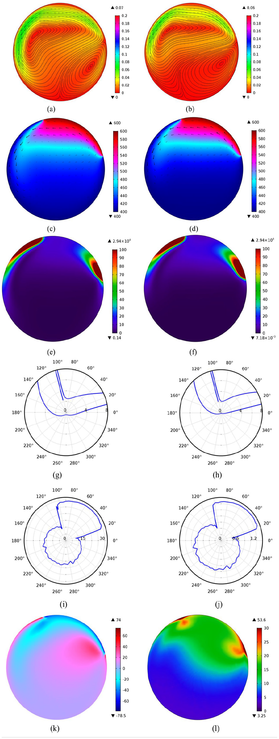
The variations of local distributions are illustrated in Figure 3 when the heater extends one-quarter the perimeter of the cavity (case 1) and is centered at φ0 = –60°. According to local velocity fields presented in Figure 3(a), we can signal the presence of two counter-rotating asymmetric distorted cells where the big one is located at the top of the enclosure and the small one is located at the bottom of the cylinder. Also note the presence of relatively higher particle motions, especially at the center of the enclosure in the area between the convective cells. It is important to note that thermal radiation does not affect the aspect of the fluid flow but might, on the contrary, provoke some visible fluid distortions, as seen in Figure 3(b). The profiles of temperature fields given in Figure 3(c) and (d) mention that the heated fluid particles are abundantly distributed throughout the enclosure, especially at the bottom of the cylinder. This creates temperature gradients in the vicinities of the cold surface, thus generating volumetric entropy due to conduction heat transfer and justifying its remarkable presence in the vicinity of the cold surface and in the discontinuities signaled at the extremities of the heat source. It is also notable that contact between convective cells is clearly visible in the profiles of conductive entropy generation for this specific heating location, as shown in Figure 3(e) and (f).

Local distributions (case 1, φ0 = –60°)—Th = 600 K, Tc = 400 K, R = 0.025 m, P = 1 atm, ε = 1: (a) velocity with radiation (m/s), (b) velocity without radiation (m/s), (c) temperature with radiation (K), (d) temperature without radiation (K), (e) conductive entropy generation with radiation (W/K m3), (f) conductive entropy generation without radiation (W/K m3), (g) conductive Nusselt number with radiation, (h) conductive Nusselt number without radiation, (i) radiative Nusselt number, (j) entropy generation due to radiation at wall (W/K m2), (k) radiative term source (kW/m3), and (l) entropy generation due to volumetric radiation (W/K m3).
Reference must be made to the fact that trends of Figure 3(g) and (h), which present the profiles of the conductive Nusselt numbers, display discontinuities on both sides of the extremities of the heat source. This justifies the high values of conductive Nusselt number, which are depicted in area generating high-temperature gradients. On the contrary, the conductive Nusselt number at the hot wall increases going away from the center of the heat source.
The profiles of local radiative Nusselt number along the sidewall and local entropy generation due to surface radiation are given in Figure 3(i) and (j), respectively. It is worth mentioning that the local radiative Nusselt number is shown as having profiles in the form of a circular arc. It is interesting to note here that surface-to-surface heat exchanges dominate heat transfer within the enclosure where the medium remains optically thin. Also noteworthy is that profiles of local entropy generation due to wall radiation are practically identical to those of local radiative Nusselt number at the sidewall. The local variations of the radiative source term and entropy generation due to volumetric radiation are given in Figure 3(k) and (l), respectively. It is worth noting that the radiative source term fields are remarkably developed in the vicinities of the cold surface. Another important feature is that negative and positive values of the radiative source term correspond to hot and cold particle areas, respectively. It is also important to note that the profiles of local entropy generation due to volumetric radiation present lower values compared to those computed owing to conduction heat transfer. It should also be mentioned that the general aspect of the corresponding trends is similar to the profiles of the absolute value of the radiative term source, where reporting significant entropy generation is due to gas radiation in the vicinities of the heat source.
The local distributions are illustrated in Figure 4 when the heater is made of one-quarter of the perimeter of the cavity (case 1) and is centered at φ0 = 0°. At first blush, reading Figure 4 remains the interpretations presented for Figure 3. More specifically, the fluid flow changes its structure when approaching a heat source location of 0°, displaying only one reduced cell. As a result, the hot fluid particles do not penetrate within the enclosure, flowing in the vicinities of walls. The temperature gradients are thus located close to walls, especially in the vicinity of discontinuities, producing remarkable entropy due to conduction heat transfer in these areas. In addition, the conductive Nusselt number decreases significantly going away from the heat source, reaching an absolute minimum at the bottom of the cylinder.

Local distributions (case 1, φ0 = 0°)—Th = 600 K, Tc = 400 K, R = 0.025 m, P = 1 atm, ε =1: (a) velocity with radiation (m/s), (b) velocity without radiation (m/s), (c) temperature with radiation (K), (d) temperature without radiation (K), (e) conductive entropy generation with radiation (W/K m3), (f) conductive entropy generation without radiation (W/K m3), (g) conductive Nusselt number with radiation, (h) conductive Nusselt number without radiation, (i) radiative Nusselt number, (j) entropy generation due to radiation at wall (W/K m2), (k) radiative term source (kW/m3), and (l) entropy generation due to volumetric radiation (W/K m3).
Figure 5 depicts the variations of local distributions when the heat source is spread across one-quarter of the sidewall and centered at φ0 = +60°. Reference must be made to the fact that heated fluid particles remain adhered to the upper sidewall of the enclosure, contrary to what is seen for negative values of the heat source center where they are abundantly distributed within the enclosure. It is worth noting that the low values of the conductive Nusselt number at the bottom of the cylinder correspond to a stagnant zone. Let us conclude by pointing out that for reasons of geometrical symmetry, the vortex cells display symmetrical profiles when the center of the heat source is close to ±90°.
Local distributions (case 1, φ0 = +60°)—Th = 600 K, Tc = 400 K, R = 0.025 m, P = 1 atm, ε =1: (a) velocity with radiation (m/s), (b) velocity without radiation (m/s), (c) temperature with radiation (K), (d) temperature without radiation (K), (e) conductive entropy generation with radiation (W/K m3), (f) conductive entropy generation without radiation (W/K m3), (g) conductive Nusselt number with radiation, (h) conductive Nusselt number without radiation, (i) radiative Nusselt number, (j) entropy generation due to radiation at wall (W/K m2), (k) radiative term source (kW/m3), and (l) entropy generation due to volumetric radiation (W/K m3).
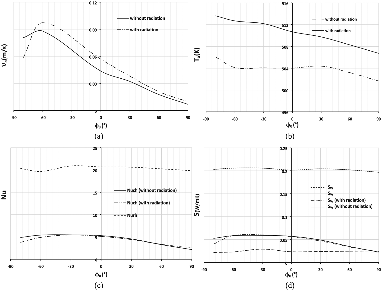
The effect of heating location on the average distributions is shown in Figure 6 when the heat source is spread across one-quarter of the sidewall. It is worth to mention that in the absence of radiation, the mean velocity presents decreasing profiles, which are slightly attenuated when the center of the heat source is close to −45°, reflecting transition from two asymmetrical convective cells to a single one. This change in the flow structure is clearly visible when radiation is taken into consideration, with the appearance of a peak corresponding to a global maximum velocity of 0.09 m/s, as shown in Figure 6(a). Especially noteworthy is the apparition of low velocity values in the vicinity of φ0 = +90°, reflecting thermal stratification. As can be seen from Figure 6(b), the temperature profiles increase progressively for heating locations lying in the range of [–90°, −60°]. This is followed by decreasing profiles in the range of [–60°, −45°] caused by the transition in flow structure from two convective cells to a single one. The average temperature displays quasi-uniform trends in the range of [–45°, 0°] followed by decreasing profiles in the range from 0° to 90°. Low values of the average temperature are depicted as we approach a heating location of +90°, providing a fair view of flow stratification. In these conditions, thermal convection is attenuated, and heat transfer in this flow regime is consequently purely conductive. The profiles of average Nusselt numbers at the heated wall are given in Figure 6(c) in order to get better apprehension of heat transfer between gas and the heat source. As can be shown, the general aspect of the profiles of the mean convective Nusselt numbers presents some visible distortions. The curves display a first stagnant phase in the range of [–90°, −60°], displaying quasi-uniform profiles. This is followed by a growing phase from −60° to −45°, indicating the passage from two convective cells to a single one. A second stagnant step is signaled in the range of [–45°, 30°] followed by slight decreasing profiles from 30° to 60°, which are subsequently attenuated in the range of [60°, 90°]. It is worth noting that the presence of thermal radiation does not appear to affect the profiles of the convective Nusselt number at the heated wall. Also notable is the quasi-uniform profile displayed by the radiative Nusselt number along the heated wall, projecting an accurate image of surface-to-surface radiative exchange. It should also be underlined that the appearance of slight differences in the values of the radiative Nusselt numbers is due to the radiative fluid participation through an optically thin medium. As expected, the profiles of the global entropy generation due to conduction heat transfer, given in Figure 6(d), remind those of the average convective Nusselt number, knowing that they are not affected by thermal radiation. We should also point out that entropy generations due to wall and volumetric radiation present quasi-uniform profiles and are substantially independent of the heating location. Moreover, it must also be pointed out that entropy generation due to surface radiation is distinctly developed compared to entropy generated due to heat conduction and gas radiation. It is also important to specify that entropy generation due volumetric radiation displays very low values since the enclosure is limited in dimensions, involving thus an optically thinner medium.

Effect of heating location on average distributions (case 1)—Th = 600 K, Tc = 400 K, R = 0.025 m, P = 1 atm, ε = 1:(a) velocity, (b) temperature, (c) Nusselt numbers, and (d) entropy generation.
Case of one-half heated enclosure (case 2)
Figure 7 depicts the variations of local velocity field according to heating location when the heat source is spread across one-half of the sidewall. The general aspect of this figure shows the appearance of a unicellular flow pattern where the heating location only affects the fluid flow intensity. Meanwhile, it should be noted that the fluid flow changes its structure by altering location of the heat source. In fact, the convective cell is practically centered within the enclosure if the center of the heat source is located at −60° with the emergence of higher particle motions within the enclosure. The interesting aspect for a heating location of 0° is the remarkable movement of fluid particles next to the wall contour of the enclosure and the fact that the cell center, which is practically motionless, is displaced to the bottom of the enclosure. Another remarkable fact for a heating location of 0° is the appearance of cell distortion, clearly visible in the absence of radiation. However, low flow velocities are depicted for a heating location close to +60°, where the convection cell is stretched, notifying the appearance of a second vortex cell at the bottom of the cylinder.

Effect of heating location on local velocity (m/s), (case 2) with radiation (on the left) and without radiation (on the right)—Th = 600 K, Tc = 400 K, R = 0.025 m, P = 1 atm, ε = 1: (a) φ0 = –60°, (b) φ0 = 0°, and (c) φ0 = +60°.
Figure 8 illustrates the effect of heating location on the average distribution when the heat source extends half the cavity perimeter. In the absence of radiation, the profile of the average velocity shows a first phase with increasing trend in the range of [–80°, −60°], reaching an absolute maximum close to −60°. A second phase with continuous decreasing tendency is observed until a corresponding heating location of +90°, where low flow velocities are depicted. A similar profile is remarked when radiation is considered, except that the corresponding peak is slightly amplified compared to that computed without thermal radiation. When thermal radiation is not considered, the average temperature presents a first phase with decreasing profile in the range of [–80°,–60°] followed by a quasi-uniform tendency from −60° to 0°. This is followed by a third phase with increasing profile until reaching a relative maximum when approaching a heating location of 30°. In a final phase, a decreasing trend is observed showing attenuation close to a heating location of 90°. As regards the average temperature when radiation is taken into consideration, the corresponding profile is relatively more developed, presenting a continuously decreasing trend. It needs to be noted that profiles of the conductive Nusselt numbers calculated with and without radiation are practically identical, presenting slightly increasing trends in the range of [–80°,–60°]. This phase is followed by quasi-uniform profiles in the range of [–45°, 0°] and decreasing tendencies from 0° to 90°, which seem to be attenuated next to the heating location of 90°. Compared to trends of the mean conductive Nusselt numbers, the profile of the average radiative Nusselt number is clearly more developed, showing a quasi-uniform tendency. On the contrary, it is also worth noting that profiles of average Nusselt numbers corresponding to one-half heated enclosure (case 2) are less developed compared to those computed when the active zone extends one-quarter the perimeter of the cavity (case 1). Furthermore, it must be pointed out that the general aspect of the global entropy generation is practically similar to those established when the heating section extends quarter the perimeter of the cavity, except that they are slightly more developed.
Effect of heating location on average distributions (case 2)—Th = 600 K, Tc = 400 K, R = 0.025 m, P = 1 atm, ε = 1: (a) velocity, (b) temperature, (c) Nusselt numbers, and (d) entropy generation.
Case of three-quarters heated enclosure (case 3)
Figure 9 describes the effect of heating location on local velocity when the heat source extends three-quarters the perimeter of the enclosure. As can be seen from this figure, the fluid particles get entrained by important flow rates when the heat source is located at −60°, showing a single convective cell located practically at the center of the enclosure. When approaching a heating location of 0°, the structure of the flow changes resulting in cell distortion, clearly visible when radiation is not taken into consideration. Especially noteworthy in the range of [0°, 60°] is transition between one and two vortex processes, altering the movement of fluid particles through low flow rates.

Effect of heating location on local velocity (m/s), (case 3) with radiation (on the left) and without radiation (on the right). Th = 600 K, Tc = 400 K, R = 0.025 m, P = 1 atm, ε = 1: (a) φ0 = –60°, (b) φ0 = 0°, and (c) φ0 = +60°.
Figure 10 illustrates the variations of average distributions according to the heat source location. In light of what was written in the “Case of one-half heated enclosure (case 2)” section, the general aspect of the mean velocity curves reminds the velocity profiles of Figure 8(a), but with reduced flow rates. In the absence of radiation, the average temperature trend shows a first phase with decreasing profile in the range of [–90°, −60°], reaching an absolute minimum in the vicinity of −60°. This is followed by a second phase with increasing profile. When radiation is considered, the average temperature presents a quasi-uniform profile in the range of [–90°, 0°], followed by an increasing tendency from 0° to 90°. A crucial feature of this figure is the fact that the two curves intersect at 45° from which the values of average temperature computed in the absence of radiation exceed those calculated when radiation is considered. Please note that curves of the average Nusselt numbers at the heated wall remind those of Figures 6(c) and 8(c), when the heat source extends one-quarter (case 1) and half (case 2) the perimeter of the enclosure, respectively. The special feature here is that profiles of average Nusselt numbers corresponding to case 3 are considerably reduced. As regards the global entropy generation, the corresponding curves present almost similar profiles to those developed in cases 1 and 2. It is also noted that curves of entropy generation due to thermal conduction, which are practically independent of thermal radiation, remind those of the average conductive Nusselt number. Another demonstrable fact is that profiles of entropy generation due to volumetric radiation and wall radiation are quasi-uniform, but the latter remains dominant.

Effect of heating location on average distributions (case 3)—Th = 600 K, Tc = 400 K, R = 0.025 m, P = 1 atm, ε = 1: (a) velocity, (b) temperature, (c) Nusselt numbers, and (d) entropy generation.
Figure 11 illustrates the energy efficiency of the physical model according to the heater size and location. One initial point to consider is the fact that case 3 with three-quarters heated enclosure represents the best convective heating, whereas case 2 with one-half heated enclosure is seen to be the worst one. Specifically, choosing a heat source centered at the top of the enclosure seems to be the best configuration to optimizing the convection heat transfer process. The coupling of radiation with free convection indicates that energy efficiency is shown to be practically independent of the heater size, but case 2, however, remains the most unfavorable configuration among the three investigated.

Effect of heater size and heater location on energy efficiency—Th = 600 K, Tc = 400 K, R = 0.025 m, P = 1 atm, ε = 1.
The effects of the heater size and location on exergy losses are presented in Figure 12, both with and without thermal radiation. At first glance, it can be shown that independently of the presence of radiation, the minimum exergy loss is achieved for case 3 with three-quarters heated enclosure, particularly when the heat source is centered at the top of the enclosure, providing the best heat transfer performance.

Effect of heater size and heater location on exergy loss—Th = 600 K, Tc = 400 K, R = 0.025 m, P = 1 atm, ε = 1.
Conclusion
In this article, a numerical computation of coupling between natural convection and radiation in a partially heated cylindrical enclosure filled with a non-gray gas is investigated. The working fluid is considered as absorbent, emissive, and non-scattering. The resolution of the radiative transfer equation is done using the Ray-Tracing method associated to the SNBcK model. The main subject of this work is the examination of the radiative contribution on heat transfer, fluid flow, and entropy generation. Energy efficiency and exergy losses are also computed in order to improve and to optimize heat transfer through the enclosure.
Based on the results obtained, some important conclusions can be made as follows:
The intensity and the structure of fluid flow are significantly affected by the heater location and the heater size, specifically in the form and the number of the convective cells.
Heat transfer and fluid flow are enhanced in the presence of thermal radiation.
Case 3 represents the optimum heater size for heat transfer process due its higher energy efficiency and lower exergy loss.
The best heat transfer performance is achieved when the heat source is centered at the top of the enclosure.
The best efficiency is obtained for pure free convection.
Footnotes
Appendix 1
Handling Editor: Dean Vučinić
Declaration of conflicting interests
The author(s) declared no potential conflicts of interest with respect to the research, authorship, and/or publication of this article.
Funding
The author(s) received no financial support for the research, authorship, and/or publication of this article.